
Pre Amplifier
Index
Microphone Preamplifier with SSM 2015 P
Published:2012/9/13 3:51:00 Author:Ecco | Keyword: Microphone, Preamplifier, SSM
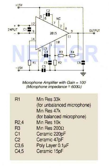
An ultra low noise audio preamplifier particularly suited to microphone preamplification including balanced microphones. The IC features wide bandwidth, low distortion only 0.007% at a gain of 100.
Source: NEXT.GR (View)
View full Circuit Diagram | Comments | Reading(1850)
Magnetic Cartridge Preamplifier (LT1028CN8)
Published:2012/9/13 3:43:00 Author:Ecco | Keyword: Magnetic Cartridge , Preamplifier
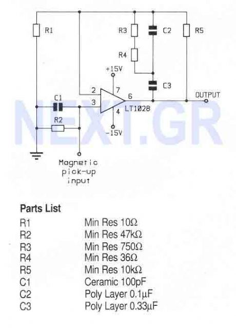
A high performance op-amp that sets a new standard of excellence in noise performance only 0.9nV/Hz with low source resistances. Total harmonic distortion is less than 0.01%. The op-amp is suitable for use in high quality audio, low noise frequency synthesizers, infrared detectors etc.
Source: NEXT.GR (View)
View full Circuit Diagram | Comments | Reading(1212)
Small leakage pre-amplifier
Published:2012/9/11 21:30:00 Author:Ecco | Keyword: Small leakage, pre-amplifier
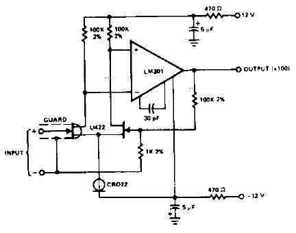
The circuit uses the LM301 has an input leakage of only 2 pA typical at 75 ° C and is used with 1 M ohm input resistance. The operating voltage has to be +-12V. (View)
View full Circuit Diagram | Comments | Reading(0)
RIAA preamplifier CA3410
Published:2012/9/11 21:02:00 Author:Ecco | Keyword: RIAA , preamplifier
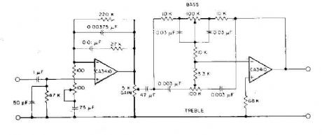
This circuit has read the RIAA equalization, tone controls, and adequate gain to drive most power amplifiers conunercial by using CA3410 op amp BiMOS. Total harmonic distortion, pushed to provide an output of 6-V, is less than 0.035% in audio-frequency range from 150 Hz to 40 kHz. Full stereo preamp is to duplicate this circuit using the CA3410 remaining two amplifiers. (View)
View full Circuit Diagram | Comments | Reading(0)
Fully adjustable preamplifier
Published:2012/9/11 20:28:00 Author:Ecco | Keyword: Fully adjustable , preamplifier
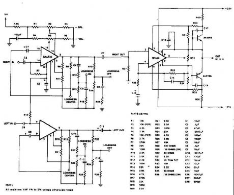
This circuit is a audio preamplifier tha has balance, tone and loudness controls. It should be suitable as an example of good design for audio application. Uses the BAA730 and NE540 chips. (View)
View full Circuit Diagram | Comments | Reading(0)
Stereo Preamplifier with balance and loudness
Published:2012/9/11 20:27:00 Author:Ecco | Keyword: Stereo Preamplifier , balance , loudness
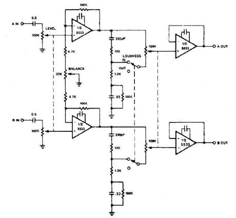
The circuit of preamplifier use the 5533 chip and features a combination of controls balance and volume. Due to the nonlinearity of the human auditory system, low frequencies must be boosted at low listening levels. Level pay, and LOUDNESS controls provide all the plays to produce the desired response from the music. (View)
View full Circuit Diagram | Comments | Reading(0)
Microphone preamplifier with TLC251
Published:2012/9/11 20:19:00 Author:Ecco | Keyword: Microphone, preamplifier
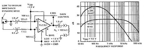
A microphone preamplifier using: om CMOS op amp with its own battery, is small enough to be placed in a case of small microphone. The amplifier operates from a 1.5V battery cathode mercury low supply currents. This preamp will operate at very low power and maintain a reasonable frequency response as well. The TLC251 is operating in low bias (operating at 1.5 V) draws a supply current of only 10 and has a year - frequency response of 3 dB 27 Hz to 4.8 kHz. With 8-pin grounded, which is designated as the polarization state high limit increases above 25 kHz. Supply current is only - 30 pA under these conditions. (View)
View full Circuit Diagram | Comments | Reading(0)
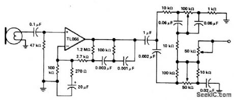
MICROPHONE_PREAMPLIFIER_WITH_TONE_CONTROL
Published:2009/6/30 2:47:00 Author:May
View full Circuit Diagram | Comments | Reading(1264)
TWO_METER_PREAMPLIFIER_FOR_HANDITALKIES
Published:2009/6/23 1:37:00 Author:May

This simple, inexpensive, wideband rf amplifier provides 14 dB gain on two meters without the use of tuned circuits. (View)
View full Circuit Diagram | Comments | Reading(949)
SINGLE_ENDED_HI_Z_MICROPHONE_PREAMP
Published:2009/6/18 23:47:00 Author:May
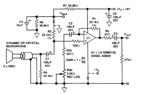
This low noise circuit works on a +5-V supply. Gain range is 20 to 40 dB and bandwidth is 20 kHz with the AD820. THD is 0.05% with 1 V RMS into a 2-kΩ load. Noise output with the input shorted is less than 200μV. (View)
View full Circuit Diagram | Comments | Reading(1475)
BALANCED_MICROPHONE_PREAMPLIFIER
Published:2009/6/18 23:44:00 Author:May
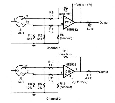
A balanced input for microphones can solve hum and noise pickup problems. R6 and R13 should equal R5 and R12, respectively. Typical values would be 10 kΩ to 22 kΩ. (View)
View full Circuit Diagram | Comments | Reading(8069)
DYNAMIC_MICROPHONE_PREAMP
Published:2009/6/18 23:43:00 Author:May
This preamplifier provides 40- to 43-dB gain when used with a low-impedance (<1kΩ) dynamic microphone (View)
View full Circuit Diagram | Comments | Reading(3)
LOW_VOLTAGE_MICROPHONE_PREAMP
Published:2009/6/18 22:41:00 Author:May
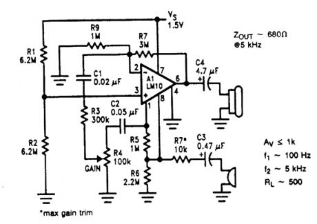
A microphone amplifier is shown. The refer-ence, with a 500-kHz unity-gain bandwidth, is used as a preamplifier with a gain of 100. Its out-put is fed through a gain-control potentiometer to the op amp, which is connected for a gain of 10. The combination gives a 60-dB gain with a 10-kHz bandwidth, unloaded, and 5 kHz loaded at 500Ω. Input impedance is 10 kΩ.Potentially, using the reference as a preampli-fier in this fashion can cause excess noise. How-ever, because the reference voltage is low, the noise contribution, which adds root-mean-square, is likewise low. The input noise voltage in this con-nection is 440-500 nV Hz, about equal to that of the op amp. (View)
View full Circuit Diagram | Comments | Reading(1119)
WIDEBAND_PREAMP
Published:2009/6/18 2:19:00 Author:May
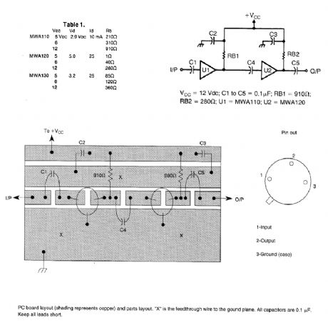
Motorola MWA 110,120,Or 130 are wideband amplifier ICs. This wideband preamp circuit can be used in many applications Keep the leads short when constructing the circuitry. (View)
View full Circuit Diagram | Comments | Reading(2131)
RECEIVER_SCANNER_PREAMP_USING_MAR_1_MMIC
Published:2009/6/18 1:50:00 Author:May
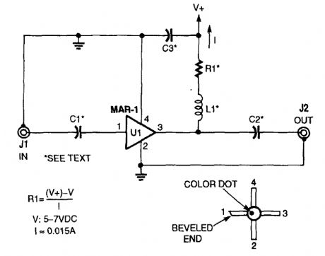
The low-cost Mini-Circuits MAR-X series of chips offer the RF builder a real advantage, with their inherent 50-Ω input and output impedances (needed for RF systems). An MAR-l-based re-ceiver/scanner preamplifier is shown. C1 and C2 are chip capacitors. Use 0.01 μF for HF, 0.001 for VHF, and 100 pF for above 100 MHz, depending on the low-frequency limit that you desire. C3 can be a ceramic disc of 0.01 μF or 0.001 μF, de-pending on frequency range. L1 is an RF choke that is suitable for the frequency range that you desire (0.1 to 10 μH). (View)
View full Circuit Diagram | Comments | Reading(2593)
HF_PREAMPLIFIER
Published:2009/6/17 23:15:00 Author:May
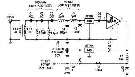
This HP SW receiver preamplifier is comprised of a broadband toroidal transformer (L1-a and L1-b), a complex LC network (comprised of a 1600-kHz, high-pass filter and a 32-MHz, low-pass fil-ter), L2 and L3 (26 turns of #26 enameled wire wound on an Amidon Associates T-50-2, red, toroidal core), a pair of resistive attenuators (ATTN1 and ATTN2), and of course, the MAR-x device. Exter-nal power for the preamp can be 9 to 12 Vdc. R1 can be increased in value for higher voltages. (View)
View full Circuit Diagram | Comments | Reading(1384)
AGC_AUDIO_PREAMP
Published:2009/6/17 22:52:00 Author:May
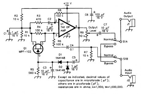


The circuit uses an easily obtained 741 op amp set for an internal gain of about 200. A portion of the op amp's output signal is rectified by the 1N4148 diodes, then filtered and fed to the gate of the FET input shunting circuit. As the output rises, more and more input shunting takes place. That is, more of the input signal is bypassed, effectively keeping the output level constant.The circuit offers a 100:1 limiting action. The input level can change over a 100:1 ratio with little or no effect on the output level. The output level itself can be set from less than unity all the way up to nearly the gain of the amplifier, making the circuit usable in other applications as well. (View)
View full Circuit Diagram | Comments | Reading(5541)
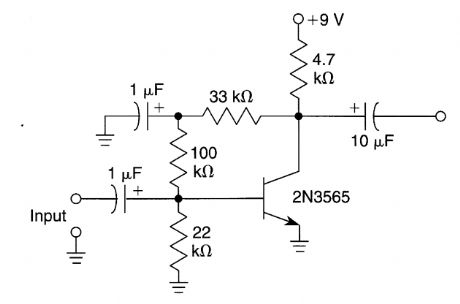
SELECTIVE_PREAMPLIFIER_FOR_INFRARED_PHOTODIODE
Published:2009/6/16 22:15:00 Author:May
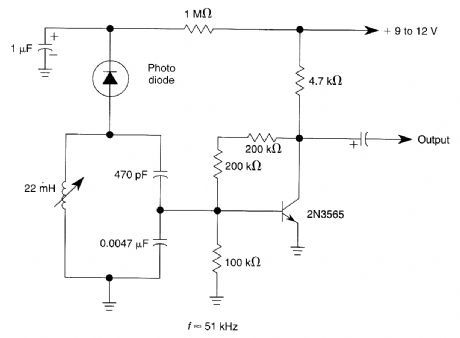
The circuit uses a tuned circuit to achieve frequency selection. Values are for operation at about 51 kHz. The 2N3565 amplifies the output developed by the tuned circuit. (View)
View full Circuit Diagram | Comments | Reading(1205)
DUAL_PREAMP
Published:2009/6/15 23:06:00 Author:May

If you wish to amplify low-levle signals,such as the output of a turntable, the signal must first be fed to this preamp. (View)
View full Circuit Diagram | Comments | Reading(1118)
LOOP_ANTENNA_PREAMPLIFIER
Published:2009/6/15 21:16:00 Author:May

This preamplifier has a built-in regeneration control boost gain selectivity. C1 is a single or multigang AM broadcast-band tuning capacitor. L1 is a ferrite loop antenna, tapped at about 15 to 25% of total turns. This circuit should prove useful for low-frequency (up to 3 MHz) reception, where a loop would be advantageous to reduce man-made noise pickup. (View)
View full Circuit Diagram | Comments | Reading(4488)
| Pages:1/2 12 |
Circuit Categories
power supply circuit
Amplifier Circuit
Basic Circuit
LED and Light Circuit
Sensor Circuit
Signal Processing
Electrical Equipment Circuit
Control Circuit
Remote Control Circuit
A/D-D/A Converter Circuit
Audio Circuit
Measuring and Test Circuit
Communication Circuit
Computer-Related Circuit
555 Circuit
Automotive Circuit
Repairing Circuit