
Analog Circuit
Index 22
Typical Applied Circuit of M50560-200P IC
Published:2011/5/16 2:42:00 Author:Michel | Keyword: IC, Applied Circuit
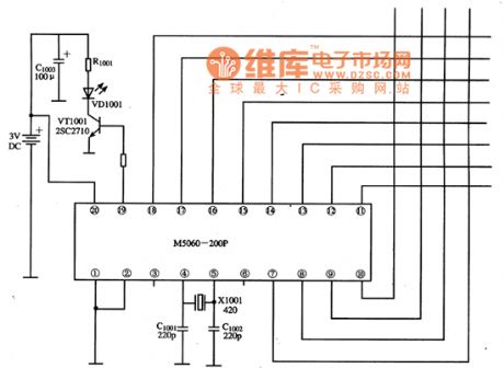
Typical Application Circuit
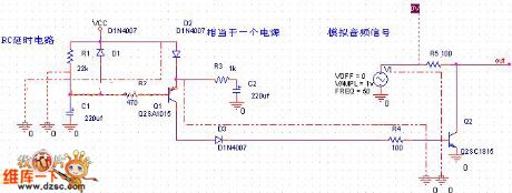
The remote control applied circuit composed of M50560-200P IC is showed as the picture.
Picture:Typical Application Circuit of M505060-200P IC (View)
View full Circuit Diagram | Comments | Reading(1655)
monolithic temperature sensor circuit
Published:2011/5/29 8:13:00 Author:chopper | Keyword: monolithic, temperature sensor
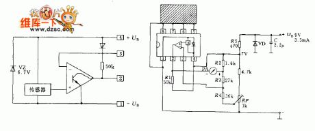
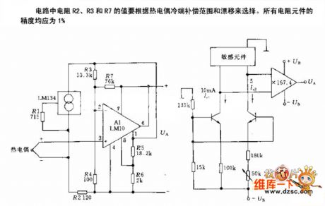
Integrated circuit LM3911 is a silicon sensor composed of operational amplifier and voltage regulator circuit.It can be a simple electrical thermometer only by using a few external components.Transistor is used as a temperature-sensing element on the silicon chip.The voltage of base and emitter of the transistor varies with temperature changes.When the temperature rises,the voltage will increase.Outside temperature intussuscepted from a copper billet will be passed on to the temperature sensor.The copper billet will be connected to pins 5~8 of the integrated circuit and the inside parts of these pins are connected to temperature sensor.
(View)
View full Circuit Diagram | Comments | Reading(708)
temperature sensor compensation circuit
Published:2011/5/23 19:36:00 Author:John | Keyword: temperature sensor
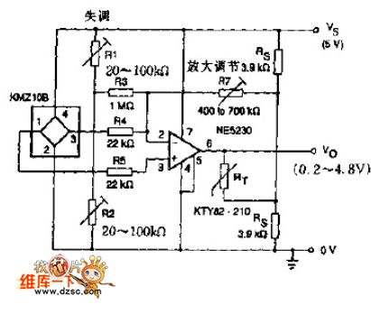
The sensor KTY series in the circuit is applied for positive or negative temperature drifting compensation. In many cases, temperature drifting of KMZ10B is negative. And an op-amp NE52300 is placed in the circuit to achieve the following functions:
1. Average (sensor to sensor) the sensitivity of temperature drift.2. Apply the potentiometer R1 and R2 for offset adjustment. 3. Use the potentiometer RT for gain adjustment.
(View)
View full Circuit Diagram | Comments | Reading(2774)
Comparator Circuit
Published:2011/5/17 9:10:00 Author:Robert | Keyword: Comparator
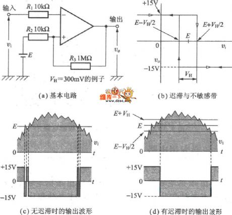
The Comparator Circuit is shown in the picture below. Picture (1) is basic circuit. Picture (2) is hysteresis and non-sensitive zone. Picture (3) is the output waveform with no hysteresis. Picture (4) is output waveform with hysteresis.
(View)
View full Circuit Diagram | Comments | Reading(777)
Current Flowing After Boot Circuit (2)
Published:2011/5/17 8:53:00 Author:Robert | Keyword: Current Flowing, Boot
The Current Flowing After Boot Circuit (2) is shown below.
(View)
View full Circuit Diagram | Comments | Reading(632)
General Analog Thermometer Circuit
Published:2011/5/12 8:07:00 Author:Robert | Keyword: Analog, Thermometer
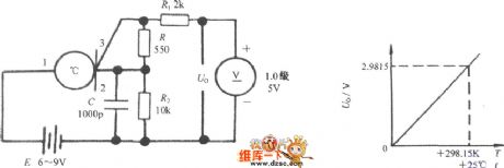
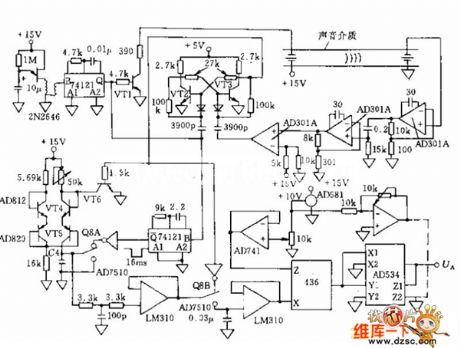
The analog thermometer circuit composed of HST1 is shown in the picture below. The HTS1 outputs current signal from its 2 foot and this foot is a high-impedance output port; but the voltage signal should output from the 3 foot and this foot is a low-impedance output port. It can use R2 to transform the current signal outputed by the sensor to be voltage signal U0, and then uses the 1.0 level 5V DC voltmeter to display the measured temperature value. When taking R2=10kΩ, the voltage temperature coefficient is 10mV/°C, the output impedance would be less than 100Ω. Just this case the output voltage-temperature (U0-T) feature curve is shown in the picture below.
(View)
View full Circuit Diagram | Comments | Reading(1328)
Typical Applied Circuit of M52340SP IC
Published:2011/5/10 19:32:00 Author: | Keyword: IC, Applied Circuit
Typical Applied Circuit
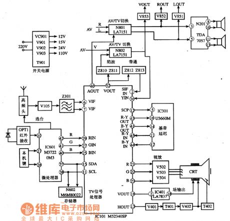
The typical applied circuit of M52340SP IC is demonstrated as the abboved picture.Konka F2136 color TV is a typical application example.
Picture:Typical Applied Circuit of M52340SP IC
Note:Ifboth image and sound accompaniment go wrong meanwhile ,we shuold check 38MHz intermediate sequancy signal which is high sequancy singalat first but changed into intermediate then whether it is added to⑥ and ⑦ feet.The M52340SPcircuit will be checked if the signal is normal. (View)
View full Circuit Diagram | Comments | Reading(862)
Typical applied Circuit Diagram of M54123 Intergrated Circuit
Published:2011/5/9 19:29:00 Author: | Keyword: Intergrated Circuit
Typical Applied Circuit Diagram
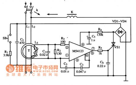
Typical applied circuit diagram of leakage protecter composed of M54123 IC is demonstrated as the abboved picture.
Picture:The typical applied circuit diagram of M54123 IC
Note:China's homegrown part number of M54123 IC is SF4123 and they can be used interchangeably directly. (View)
View full Circuit Diagram | Comments | Reading(3026)
Heteropolarity Turn-Off Absorption Circuit
Published:2011/5/5 1:39:00 Author:Robert | Keyword: Heteropolarity, Turn-Off, Absorption
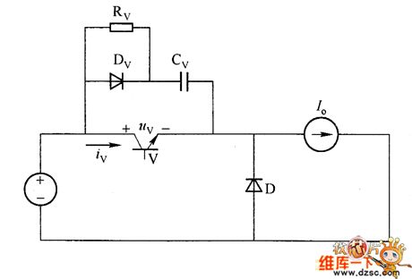
The picture 1 shows the heteropolarity turn-off absorption circuit which has a capacitor in parallel with the switch. When the switch is conducted, the capacitor Cv discharges quickly through the switch V, which makes the switch's additional current large during the conducting moment, and this could damage the switch. To avoid this situation, the pratical shutdown absorption circuitis RCD networks. It is called heteropolarity turn-Off absorption circuit because there are diodes in it. The picture 2 shows the polarized snubber circuit -- application of RCD networks in buck converter, and it is in parallel with the switch.
The compositionof the RCDis using a resistance Rv in parallel with a diode Dv, then take them in series with a capacitor Cv. The Rv's function is limit the Cv's discharging current when the swith is conducted, and also it transfers the energy in Cv to the resistance Rv to be consumed away. The diode Dv's function is making Cv be charged through the diode Dv when the switch is closed, and also the Rv coube be shorted by Dv.
(View)
View full Circuit Diagram | Comments | Reading(1215)
Pincushion Correction Circuit-Discrete Circuit Diagram
Published:2011/5/4 8:17:00 Author:Robert | Keyword: Pincushion Correction, Discrete
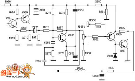
It is the parabolic wave signal addedon the r520, and the user can adjust the parabolic wave signal amplitude by adjusting the r520, which canadjust the pincushion correction value as well. It is DC voltage added on the r523, and the user can adjust the line width by adjusting r523.
This second circuit extracted from the Venus d2918 type pincushion correction circuit, whichhasjust V951 and v950 two-stage amplification more than the firstpincushion correction circuit shown below. The reason is that the field sawtooth wave is not taken from field deflection coilssampling resistor, but from tda8838's 46 foot, so thatit'sadded a two-stage amplification due to its small magnitude.
The models which use this pincushion correction circuit have: Korea Samsung mc-15 module, Venus c6418, v6458, Peony 64c1, Lehua ct6388w and so on.
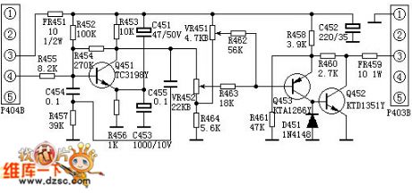
The field sawtooth wave voltage is send to the pincushion correction circuit from the p404's 4 foot, and the r455, c454, r457 make up the integral circuit to integrate the field swatooth wave and produce the up-convexparabolic wave voltage. This voltage then is added on the b polar of the parabolic wave shaping and amplifying tube. Afteramplifying and shaping the c polar output 9V (peak-peak value) down-convex parabolic wave voltage. Then after the level width adjustment, left-rightpincushion distortion adjustment network made up by the vr451, vr452, r464, r463, r462, this voltage wave is added to the polar of the compound tube made up by q453 and q452. After amplifying the q452's c polar outputs 12.5V (peak-peak value) parabolic wave voltage. At last this voltage wave is send to the line scan circuit from fr459 and p403's 3 foot to modulate the line scan current. So this process achieve the goal of pincushion distortioncorrection.
The vr451 is theline width adjustment potentiometer, thevr452 is pincushion distortion correction potentiometer.
(View)
View full Circuit Diagram | Comments | Reading(1657)
Parallel Capacitor Circuit
Published:2011/5/4 8:19:00 Author:Robert | Keyword: Parallel, Capacitor

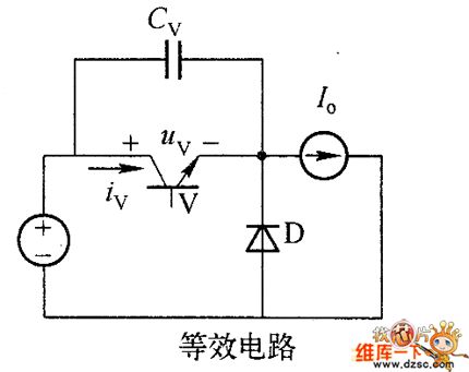
1.Parallel Capacitor
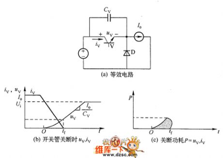
The simplestturn-off snubber circuitis to add the switch with a parallel capasitor Cv, which is shown in picture 1 (a), to limit the rising speed of the switch tubevoltage during its closing time which is shown below. The current before the switch tubeclosed is Io. The more Cv is, the slower therising speed of the switch tube voltageis, and the less power consumption of switch would be. The picture 1(b) and (c) shows the Uv, Iv and P during the closing time in separately. The picture 1 shows the parallel capacitor of the switch tube in the buck converter.
(View)
View full Circuit Diagram | Comments | Reading(726)
NTJD4001N、NTJD4401N Internal Circuit
Published:2011/5/3 3:00:00 Author:Felicity | Keyword: Internal Circuit,
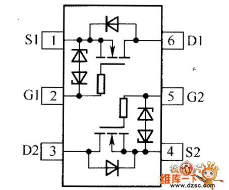
The picture above shows NTJD4401N、NTJD4401N Internal Circuit . (View)
View full Circuit Diagram | Comments | Reading(775)
HTJD4105C、NTJD4401N Internal Circuit
Published:2011/5/3 2:41:00 Author:Felicity | Keyword: Internal Circuit
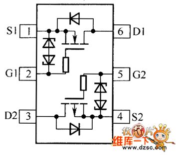
NTJD4105C、NTJD4401C Internal Circuit is showed in the piture above. (View)
View full Circuit Diagram | Comments | Reading(679)
Fahrenheit Thermometer Principle Circuit
Published:2011/5/3 2:10:00 Author:Felicity | Keyword: Fahrenheit Thermometer Principle Circuit,
Fahrenheit Thermometer Principle Circuit is showed in the picture above. (View)
View full Circuit Diagram | Comments | Reading(619)
Principle Circuit of Medical Thermometer
Published:2011/5/3 2:13:00 Author:Felicity | Keyword: Principle Circuit of Medical Thermometer ,
Principle Circuit of Medical Thermometer is showed in the picture above. (View)
View full Circuit Diagram | Comments | Reading(1085)
Principle Circuit of Temperature Measurement
Published:2011/5/3 2:17:00 Author:Felicity | Keyword: Principle Circuit of Temperature Measurement,
Principle Circuit of Temperature Measurement is showed in the picture above. (View)
View full Circuit Diagram | Comments | Reading(647)
Series Inductance Circuit
Published:2011/4/30 19:43:00 Author:Robert | Keyword: Series Inductance

The most simplest open absorbing circuit is thatthe inductance Lv connects to the switchingtubein series, which shows in picture (a). Picture(b) and (c) separately shows the uv, iv and P curve of the opening process. This illustrates thatafter adding series inductance, it limits the switching tube current's uprising speed , and decrease the power dissipation of the switch.
(View)
View full Circuit Diagram | Comments | Reading(560)
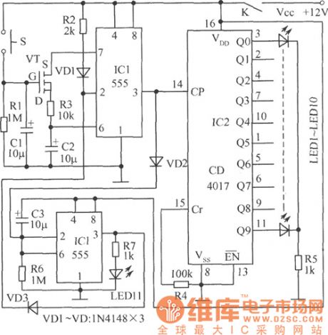
Analog turning disc guessing award device circuit diagram
Published:2011/4/28 21:39:00 Author:Ecco | Keyword: Analog, turning disc , guessing award device
View full Circuit Diagram | Comments | Reading(626)
XTR101 ELectrlcal Bridge InPut, Voltage Excitation Circuit
Published:2011/4/26 8:39:00 Author:Robert | Keyword: ELectrical Bridge InPut, Voltage Excitation
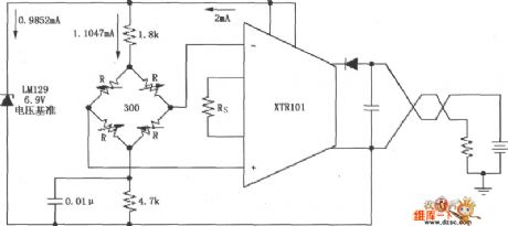
As shown, this circuit uses the voltage regulator tube LM129 to generate a 6.9V voltage reference, andthe 6.9V voltage reference provides 1.0147mA current to the electrical bridge. The electrical bridge could be variable resistance bridge type sensors like the pressure sensor etc.
(View)
View full Circuit Diagram | Comments | Reading(815)
LM567 Internal Structure Circuit
Published:2011/4/24 7:52:00 Author:Robert | Keyword: Internal Structure

LM567 Internal Structure Circuit is shown below:
(View)
View full Circuit Diagram | Comments | Reading(842)
| Pages:22/24 At 2021222324 |
Circuit Categories
power supply circuit
Amplifier Circuit
Basic Circuit
LED and Light Circuit
Sensor Circuit
Signal Processing
Electrical Equipment Circuit
Control Circuit
Remote Control Circuit
A/D-D/A Converter Circuit
Audio Circuit
Measuring and Test Circuit
Communication Circuit
Computer-Related Circuit
555 Circuit
Automotive Circuit
Repairing Circuit