
Analog Circuit
Index 21
WIRELESS_IR_HEADPHONE_TRANSMITTER
Published:2009/6/16 22:17:00 Author:May
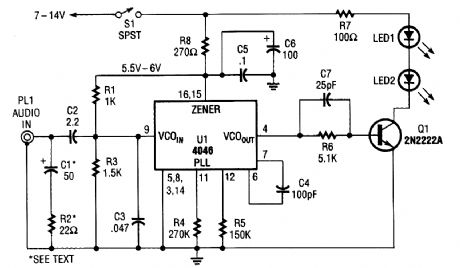


The transmitter for the wireless headphones is built around a CD4046 CMOS phase-locked loop, coupled with a driver transistor, and a pair of infrared LEDs. Although the CD4046 is comprised of two phase comparators, a voltage-controlled oscillator (or VCO), a source follower, and a zener ref-erence, only its VC0 is used in this application. (View)
View full Circuit Diagram | Comments | Reading(0)
INFRARED_RECEIVER
Published:2009/6/16 22:14:00 Author:May
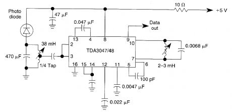
The circuit operates from a 5-V supply and has a current consumption of 2 mA. The output is a current source that drives or suppresses a current of more than 75 pA with a voltage swing of 4.5 V.The Q-killer circuit eliminates distortion of the output pulses because of the decay of the tuned in-put circuit at high input voltages. The input circuit is protected against signals of more than 600 mV by an input limiter. The typical input is an AM signal at a frequency of 36 kHz. (View)
View full Circuit Diagram | Comments | Reading(0)
AUDIO_NOTCH_FILTER_FOR_SHORTWAVE_RECEIVERS
Published:2009/6/16 2:45:00 Author:May
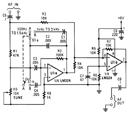
The notch filter can be added to just about any receiver to attenuate a single frequency by more Lhan 30 dB. This filter should be handy for reducing heterodynes and whistles. (View)
View full Circuit Diagram | Comments | Reading(1159)
10_TO_1_Hz_TIMEBASE
Published:2009/6/15 21:16:00 Author:May
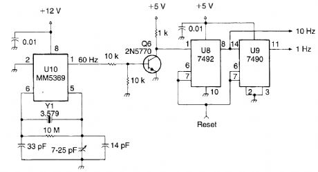
This system uses an MM5369 IC to derive a 60-Hz signal from a TV burst crystal (3579 MHz). V8 and V9 produce a 10-Hz and 1-Hz signal from this 60-Hz signal. Y1 can be any parallel-mode 3.579-MHz crystal. (View)
View full Circuit Diagram | Comments | Reading(1631)
CRYSTAL_ACTIVITY_TESTER
Published:2009/6/15 21:15:00 Author:May
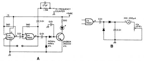
This circuit will check a crystal for activity.Two sections of a 7400 act as an oscillator and its out-put is rectified and drives an npn transistor that switches an LED (Fig.A).In Fig.B, a meter replaces the LED. (View)
View full Circuit Diagram | Comments | Reading(2)
MULTI_OUTPUT_TIMEBASE
Published:2009/6/15 21:12:00 Author:May
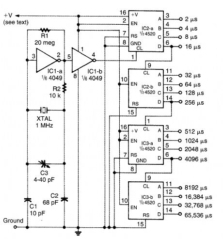
A 1-MHz oscillator drives a binary counter to produce pulse widths from 2 to 65,536 ms. V+ is any CMOS suitable level (5 to 15 V, etc.). (View)
View full Circuit Diagram | Comments | Reading(2098)
LOW_FREQUENCY_CRYSTAL_OSCILLATOR
Published:2009/6/15 20:55:00 Author:May
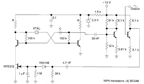
Q1, Q2, and the associated circuitry form a modified astable multivibrator in which the loop gain is automatically adjusted to the threshold of oscillation by means of field effect transistor Q3. Q4 lin-early amplifies the signal present at the collector of Q2 and isolates the oscillator section of the cir-cuit from the output. This stage features wideband operation and delivers a clean 2.5-V amplitude sine wave into a resistive load greater than or equal to 20 kΩ. The stage comprising Q5 has a voltage gain of 1 and its sole purpose is to isolate the nonlinear effects of rectifier Dl from the output. (View)
View full Circuit Diagram | Comments | Reading(2027)
DUAL_BAND_LOOP_ANTENNA_FOR_80__160_m
Published:2009/6/15 20:48:00 Author:May
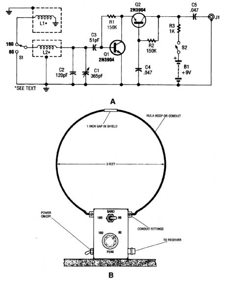
This antenna might help to reduce power-line noise. A plastic hula hoop or conduit 3 feet in diameter, covered with aluminum foil as a shield is used for L1 and L2. L1 is two turns and L2 is one turn, threaded through the loop. S1 selects 160- or 80-m operation. Q1 and Q2 form a preamplifier for the loop antenna. Do not transmit with this antenna-it is for receiving only. (View)
View full Circuit Diagram | Comments | Reading(2554)
ZIVA-4.1 DVD decoding processing integreated circuit diagram
Published:2011/7/16 2:45:00 Author:leo | Keyword: Decoding processing integreated circuit, DVD devices
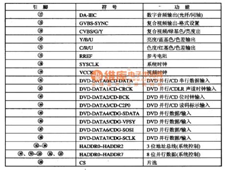
ZIVA-4.1 is a new type of DVD decoding processing integrated circuit. It is widely used in all kinds of DVD devices, for example, BuBuGao series in China and so on.
1.Function Features:The ZIVA-4.1 is used to decode the signals which are from chips and pass through UDE interface circuit. It returns the signals to analog video signals and audio signals. And the analog video signals pass through decoding chip ZIVA-4.1 directly. Audio signals are sent to audio D/A converter and output 5.1 channel analog signals, which are filtered then output.
2.Pin functions and data:ZIVA-4.1 adopts 208 pin package and all functions are shown in the picture. (View)
View full Circuit Diagram | Comments | Reading(742)
Driving Circuit By Using Speed-Up Capacitor
Published:2011/7/16 9:32:00 Author:Robert | Keyword: Driving, Speed-Up Capacitor
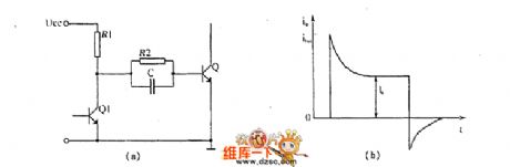
The picture shows the driving circuit by using speed-up capacitor. (View)
View full Circuit Diagram | Comments | Reading(1971)
One Normal Type Driving Circuit
Published:2011/7/16 9:08:00 Author:Robert | Keyword: Normal, Driving
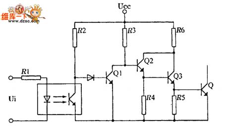
The picture shows the one normal type driving circuit. (View)
View full Circuit Diagram | Comments | Reading(601)
TOP2l2Y/P/G-PWM single chip switch source integrated circuit
Published:2011/7/13 20:11:00 Author:leo | Keyword: PWM, single chip, integrated circuit
TOP212 is a kind of PWM single chip switch source integrated circuit which is made by Power company in America. It is widely used in DVD, VCD, computer and LCD, air conditioner control system and other home appliances switch power source circuit.
TOP212Y/P/G has three packages which is different from each other from the suffix.(1)TOP212Y. It uses TO-220 package and has small thermal slug. The chip of thermal slug is connected to source S port and belongs to the classical signal line and three ports part.(2)TOP212P. It uses DIP-8 package which belongs to dual line eight pins package. And its pin ①-③ and ⑥-⑧ all connect to source S port. (View)
View full Circuit Diagram | Comments | Reading(560)
ZIVA D6 MPEG-2 decoding intergrated circuit diagram
Published:2011/7/13 19:39:00 Author:leo | Keyword: Decoding intergrated circuit, MPEG-2/2 audio
(View)
View full Circuit Diagram | Comments | Reading(234)
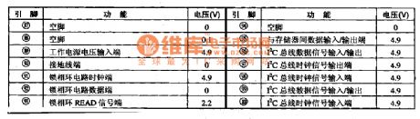
WE9142 Microcomputer dialing integreated circuit
Published:2011/7/13 19:41:00 Author:leo | Keyword: Microcomputer, dialing integrated circuit
WE9142 is a kind of microcomputer dialing integrated circuit which is widely used in all kinds of telephones.The integrated circuit WE9142 adopts 22-pin dual-line package. Pin function and related data are show in the picture, please check. (View)
View full Circuit Diagram | Comments | Reading(522)
MC13007-Single television small signal processing circuit
Published:2011/7/13 19:42:00 Author:leo | Keyword: Small signal processing circuit, 200 linear circuits
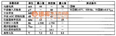
MCI3007 is a kind of integrated circuit made by Motorola. It contains 200 linear circuits and 200 logic circuits. It can be used to clear all small signals processing circuit except accompanying sound signals. It contains intermediate frequency amplifier, video detector, video processing circuit, noise control circuit and so on. Its inner circuit diagram and pin functions are shown in the picture.
The function of MC13007 has following features:
Video detector adopts whole wave detecting circuit. Usually, the common wave detector uses synchronous wave detecting circuit but MC113007 uses balanced diode whole wave detecting circuit.
It has multi function video processing circuit.
Its oscillator circuit adopts double horizontal frequency mode. (View)
View full Circuit Diagram | Comments | Reading(691)
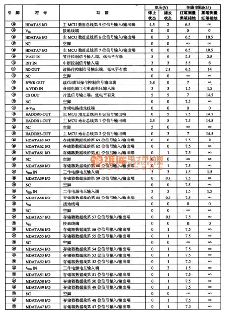
MB94918-AG3-Vice micro computer and vice photo MID screen show control integrated circuit
Published:2011/7/13 19:43:00 Author:leo | Keyword: Vice micro computer, vice photo MID screen, Mitsubishi
MB94918-AG3 is a kind of vice micro computer and vice photo MID screen show control integrated circuit made by Mitsubishi, which is widely used in sony series big screen television.Pin functions and data:MB94918-AG3 adopts 100 pins dual-line construction. Its pin functions and related data are shown in the picture. (View)
View full Circuit Diagram | Comments | Reading(570)
TLC5733MPM-A/D convertor integrated circuit
Published:2011/7/10 3:07:00 Author:leo | Keyword: A/D convertor, luminance signals processing circuit
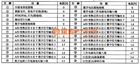
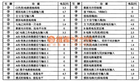
TLC5733MPM is a kind of A/D convertor integrated circuit produced by Toshiba. It is used to convert the A/D signals in the DTV.
1.Function features:The integrated circuit TLC5733MPM contains A/D converting 8 bits luminance signals processing circuit and 8 bits color signal processing solution circuit, memory circuit, mode control circuit, center U, V signal processing circuit, NTSC/PAL switch converting control circuit, main luminance signal processing circuit as well as other related circuit.
2.Pin functions and related data:TLC5733MPM adopts 64 pins dual line package. Its functions and related data are shown in the picture. (View)
View full Circuit Diagram | Comments | Reading(629)
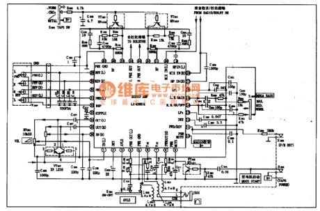
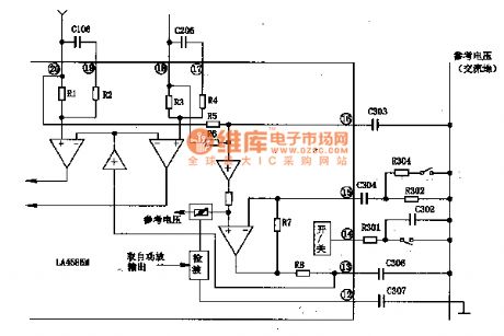
LA4585M-Signal chip playback integrated circuit
Published:2011/7/10 3:18:00 Author:leo | Keyword: Signal chip playback, complete function
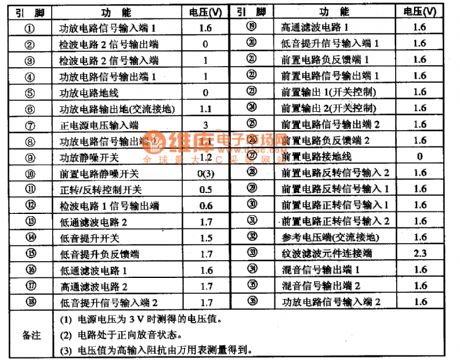
LA4585M is a type of signal chip playback integrated circuit produced by Sanyo Company. It has complete function and is widely used in Sony walk man and micro players.
1.Main functions:LA4585M contains dual channel fronted amplifier, dual channel power amplifier, system control circuit, bass improving circuit as well as peripheral circuit, such as auto reverse, audio source converting, dynamic audio source improving, auto volume limiting, noise control and other functions. LA4585M uses 36 pins package whose work voltage is 3 V and its pin functions are shown in the picture.
2.LA4585M classic applying circuit
3. Singal process
(View)
View full Circuit Diagram | Comments | Reading(946)
LA7846N-Vertical scanning output thick-film integrated circuit
Published:2011/6/30 15:45:00 Author:leo | Keyword: LA7846N-Vertical scanning output thick-film integrated circuit
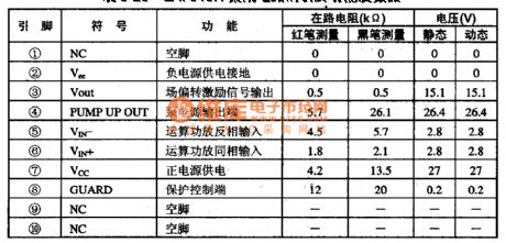
LA7846N is vertical scanning output thick-film integrated circuit which is widely used in big screen color television.
Function features:The integrated circuit LA7846N contains field deflection urging circuit, field deflection power amplifier circuit, pump power supply circuit, protecting circuit and other related circuits.
Pin functions and data:The integrated circuit LA7846N uses 10 pin single line package. Pin functions and data are shown in the picture. (View)
View full Circuit Diagram | Comments | Reading(916)
Unijunction crystal thyristor trigger circuit
Published:2011/7/4 19:21:00 Author:Christina | Keyword: Unijunction crystal, thyristor, trigger
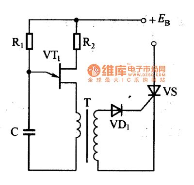
The thyristor trigger circuit is as shown in figure 1. The unijunction crystal thyristor forms the self-excited multivibrator, the series pulse current which is produced by it flows through the pulse transformer T, so the secondary stage of the transformer T will produce a series of pulse voltage, the VD1 cuts the negative pulse of this series pulse and this pulse adds to the triggered thyristors VS between the control electrode and the cathode.
The pulse transformer of this circuit can be used to trigger the pulse generating circuit and isolate the thyristor main circuit.
Figure 1 The thyristor trigger circuit
(View)
View full Circuit Diagram | Comments | Reading(1465)
| Pages:21/24 At 2021222324 |
Circuit Categories
power supply circuit
Amplifier Circuit
Basic Circuit
LED and Light Circuit
Sensor Circuit
Signal Processing
Electrical Equipment Circuit
Control Circuit
Remote Control Circuit
A/D-D/A Converter Circuit
Audio Circuit
Measuring and Test Circuit
Communication Circuit
Computer-Related Circuit
555 Circuit
Automotive Circuit
Repairing Circuit