
Analog Circuit
Index 20
LOW_DISTORTION_COMPOSITE±100_mA_LINE_DRIVER
Published:2009/6/18 4:54:00 Author:May
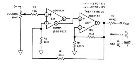
This line driver combines the high input impedance of an FET-input IC and a 100-mA op amp.U1's output is left open. The compensation terminal (pins) drive U2's high-Z input for increased overall phase margin. Gain is 14 dB, THD +N at 5 V, and RMS output is around 0.001% below 20 kHz. (View)
View full Circuit Diagram | Comments | Reading(1151)
TTL_BASED_SPEAKER_DRIVER
Published:2009/6/18 4:52:00 Author:May
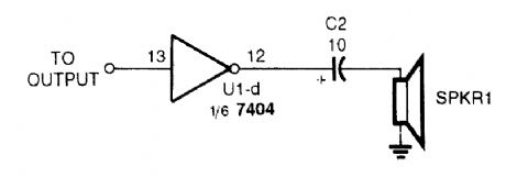
A TTL IC, such as a 7404, can drive a small speaker with enough audio to be used as an alarm or annunciator. The speaker can be a 32- or 100-Ω unit. (View)
View full Circuit Diagram | Comments | Reading(1073)
HIGH_SIDE_MOSFET_DRIVER
Published:2009/6/18 4:51:00 Author:May
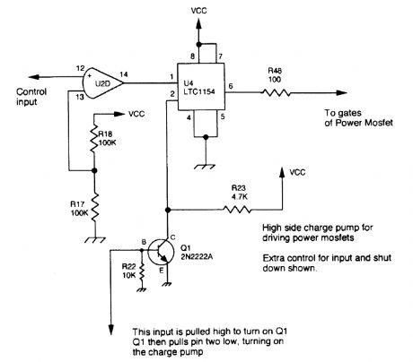
A Linear Technology LTC1154 is used as a charge pump to drive the gate of a high-side power MOSFET. (View)
View full Circuit Diagram | Comments | Reading(1381)
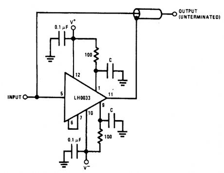
HIGH_SPEED_SHIELD_LINE_DRIVER
Published:2009/6/18 4:42:00 Author:May
View full Circuit Diagram | Comments | Reading(718)
STEREO_LINE_DRIVER
Published:2009/6/18 4:42:00 Author:May


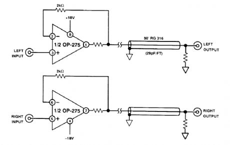
One Analog Devices OP-275 can be used for stereo line driver applications. (View)
View full Circuit Diagram | Comments | Reading(766)
TWO_INPUT_VIDEO_MUX_CABLE_DRIVER
Published:2009/6/18 4:29:00 Author:May

View full Circuit Diagram | Comments | Reading(658)
MULTIPLEXED_BCD_DECODER_DRIVER_CIRCUIT
Published:2009/6/18 4:12:00 Author:May
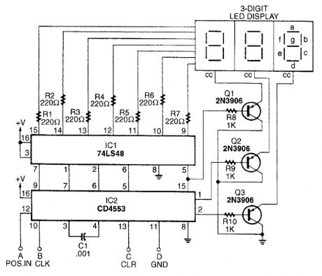
The BCD decoder-driver circuit will interface with any standard BCD output to produce a digital display. (View)
View full Circuit Diagram | Comments | Reading(2459)
COMBINATORIAL_LOGIC_MULTIPLEXER
Published:2009/6/18 3:23:00 Author:May
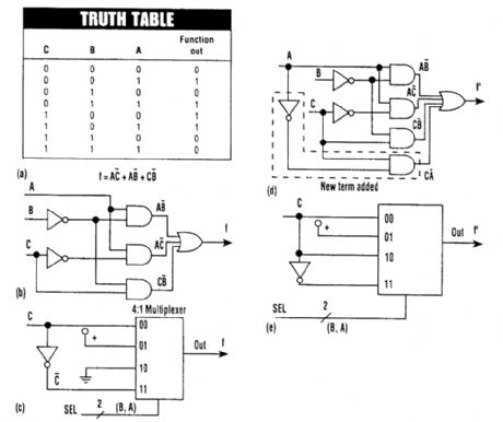
Combinatorial logic can be implemented simply by using a multiplexer instead of logic gates.Shown are the truth table(A), its logic circuit(B), and the multiplexer connections(C). If the logic circuitry is changed(D), the multiplexer would be reconnected(E). (View)
View full Circuit Diagram | Comments | Reading(994)
TRANSCEIVER_MEMORY_BACKUP
Published:2009/6/18 2:52:00 Author:May

Although designed for a Kenwood TR7730, this idea might be adapted to other transceivers. This circuit will retain the frequencies in memory while moving the rig from car to house and vice versa. When connected to an external power source, battery B1 is charged through R1 and D1.D1 prevents B1 from discharging when connected to an extemal supply that is tumed off. When extemal power is removed, D2 provides a current path to the TR-7730 to retain the memory's contents. However, the TR-7730 power switch should be tumed off before extemal power is removed because B1 will not provide power for normal operation. (View)
View full Circuit Diagram | Comments | Reading(880)
ONE_WATT_CW_TRANSMITTER
Published:2009/6/18 2:49:00 Author:May
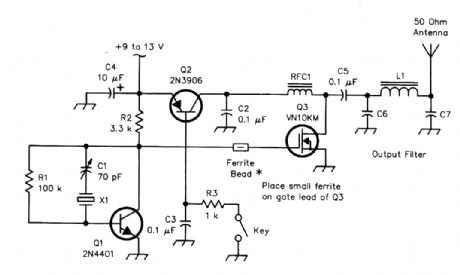
C6,C7 L1820 pF disc ceramic (160 meters) 33 turns,#30, T37-2 (160 meters) 470 pF disc ceramic (80 meters) 23 turns,#30, T37-2 (80 meters) 220 pF disc ceramic (40 meters) 17 turns,#30, T37-2 (40 meters) 150 pF disc ceramic (30 meters) 14 turns,#30, T37-2 (30 meters) 100 pF disc ceramic (20 meters) 12 turns,#30, T37-2 (20 meters) 82 pF disc ceramic (17 meters) 10 turns,#30, T37-2 (17 meters) (View)
View full Circuit Diagram | Comments | Reading(1371)
AUDIBLE_SWR_DETECTOR_ADAPTER
Published:2009/6/18 2:39:00 Author:May
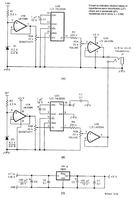
This SWR detector audio adapter is designed specifically for blind or vision-impaired atrtateurs, but anyone can use it. Instead of using a meter (or meters) to indicate antenna system forward and reflected voltages, this adapter generates two tones with frequencies that are proportional to the re-spective voltages. The tones are fed to a pair of stereo headphones (the miniature types are ideal) so that one ear hears the forward-voltage tone and the other ear hears the reflected-voltage tone. Thus, tuning up a transmitter is simply a matter of tuning for the highest-pitched tone in the left ear and the lowest-pitched tone in the right ear. (View)
View full Circuit Diagram | Comments | Reading(878)
LOGIC_PULSER
Published:2009/6/17 21:24:00 Author:May
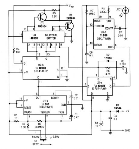
The logic pulser generates pulses at 500 Hz or 0.5 Hz. When the pulser's tip connects to an in-put that is already being driven high or low, the pulser senses the logic state and automatically pulses the input briefly to the opposite state. (View)
View full Circuit Diagram | Comments | Reading(3)
SAFETU_CIRCUIT
Published:2009/6/17 20:41:00 Author:May
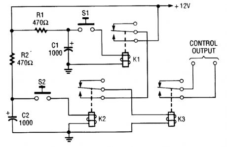
Because of the finite hold-on time of delay circuits R1/C1 and R2/C2, both S1 and S2 must be pressed at the same time to power up the load. (View)
View full Circuit Diagram | Comments | Reading(689)
ELECTRONIC_FUSE
Published:2009/6/17 20:39:00 Author:May
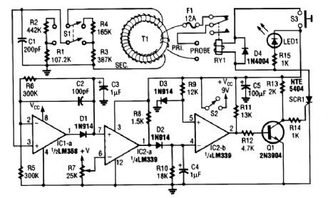
Basically, this circuit is an adjustable electronic circuit breaker, containing a toroidal transformer Lhat senses 60-Hz load current. T1 has a two-turn winding for primary, and 100 turns of #30 gauge wire for the secondary. A high-low range switch selects 0.1 to 6 A or 1 to 12 A. The primary winding of T1 carries fuL load current and voltage; should be suitably insulated, as should be RY1. (View)
View full Circuit Diagram | Comments | Reading(5)
43925_MHz_ATV_DOWNCONVERTER
Published:2009/6/17 4:18:00 Author:May
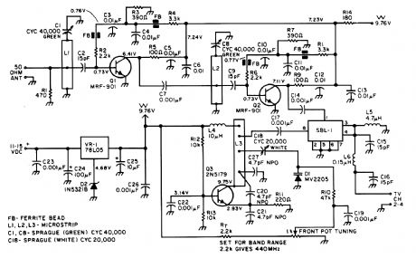
Most ATV (Amateur Television] transmitters transmit a DSB signal and commercial television stations use a VSB (Vestigial Sideband) signal. This fact is made use of in this converter to use the lower sideband. This results in less interference from repeaters that occupy the 440- to 445-MHz por-tion of the band. However, this approach might suffer from VHF image responses from channel 29, if that channel is active in your area. (View)
View full Circuit Diagram | Comments | Reading(887)
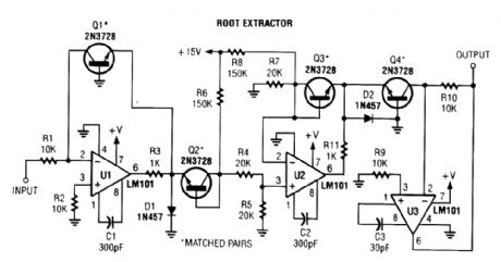
ROOT_EXTRACTOR
Published:2009/6/17 3:29:00 Author:May
View full Circuit Diagram | Comments | Reading(0)
FREQUENCY_MULTIPLIER_WITHOUT_PLL
Published:2009/6/17 1:53:00 Author:May
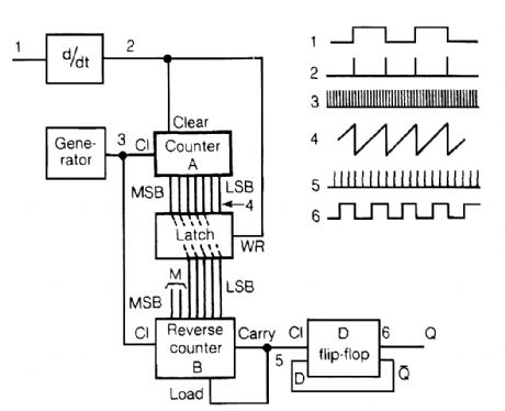
An input rectangular signal is differentiated and short impulses are formed from its edges. These impulses write the content of counter A to a latch that clears the counter after a very short time. Counter A counts impulses of the frequency fo that are much greater than that of the input signal. The pulses come from an impulse generator. Thus, the number, which is written to the latch, expresses the number of these intpulses between the edges of the input signal. The impulses from the same generator pass to (reverse) counter B. The carry impulse loads the content of the latch to counter B. The latch is connected with the reverse counter such that the number written to this counter is 2M times smaller than the number introduced to the latch. This can be readily achieved by omitting M most significant bites of counter B. Because the number loaded to counter B is 2M times smaller than the number in the latch, the carry impulses of counter B have frequency 2M times greater than the frequendy of the impulses at the output of the differentiator. The cany impulses are fed to a D flip-flop, which divides their frequency by two. In this way, the output frequency is 2M greater than input frequency fo as long as the frequency of impulse generator fg is much greater than 2Mfo. (View)
View full Circuit Diagram | Comments | Reading(1005)
ONE_WAY_VOICE_ACTIVATED_INTERCOM
Published:2009/6/16 22:57:00 Author:May
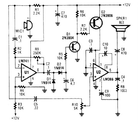
An omnidirectional electret microphone can be used to pick up the sound and convert it into an electrical signal. The output of the microphone is fed along two paths. In the first path, the signal is sent to the inverting input at pin 6. In the second path, the microphone signal is fed to the non-in-verting input of U2, where it is amplified and output to the speaker, SPKR1. (View)
View full Circuit Diagram | Comments | Reading(1337)
IR_RECEIVER
Published:2009/6/16 22:26:00 Author:May
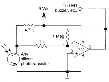
This circuitis just about the simplest IR ro-celver you can build The parts are cheap,the lay-outis not critical,and a 9-V battery will last a longtime (View)
View full Circuit Diagram | Comments | Reading(3)
WIRELESS_IR_HEADPHONE_RECEIVER
Published:2009/6/16 22:18:00 Author:May
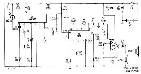
IR detector diode D1 intercepts the IR signal at around 40 kHz and feeds it from U1, a high-gain preamp, to PLL, U2, a 4046 configured to serve as an FM detector. U3 is an audio amplifier that feeds a pair of headphones or a speaker. (View)
View full Circuit Diagram | Comments | Reading(0)
| Pages:20/24 1234567891011121314151617181920Under 20 |
Circuit Categories
power supply circuit
Amplifier Circuit
Basic Circuit
LED and Light Circuit
Sensor Circuit
Signal Processing
Electrical Equipment Circuit
Control Circuit
Remote Control Circuit
A/D-D/A Converter Circuit
Audio Circuit
Measuring and Test Circuit
Communication Circuit
Computer-Related Circuit
555 Circuit
Automotive Circuit
Repairing Circuit