
Analog Circuit
Index 13
ELECTRONIC_WHISTLE
Published:2009/6/24 2:42:00 Author:May
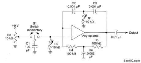
The circuit shown is a twin-tee oscillator. R1 varies the pitch, R2 the duration, and R3 the for-mat (bell, rise 8u fall time, etc.). Vary R4, R5, C4 and C2, C3 for large shifts in frequency. (View)
View full Circuit Diagram | Comments | Reading(822)
AUDIO_DYNAMIC_NOISE_REDUCTION_SYSTEM
Published:2009/6/24 2:41:00 Author:May
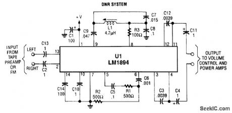
U1 is a dedicated IC (National Semiconductor) that achieves up to adaptive bandwidth scheme and a psycho acoustic masking technique. (View)
View full Circuit Diagram | Comments | Reading(1476)
VARIABLE_VOLTAGE_REGULATOR_WITH_CURRENT_CROWBAR_LIMITING
Published:2009/6/24 2:40:00 Author:May
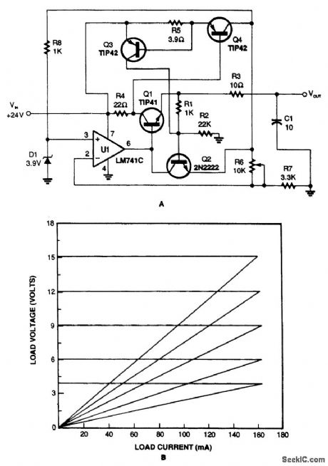


The variable voltage regulator with current-crowbar limiting, shown in Fig. 71-1A, overcomes the disadvantages of constant and foldback limiting. As you can see in the graph (Fig. 71-1B), the current crowbar quickly shuts down the supplied power when a preset current is exceeded. It also has excellent load regulation over its operating range. (View)
View full Circuit Diagram | Comments | Reading(1179)
TONE_ENCODER
Published:2009/6/24 2:35:00 Author:May
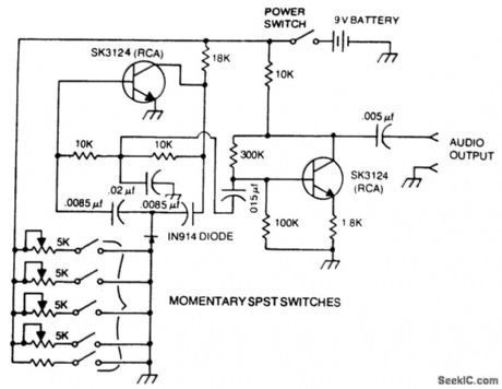
A basic twin-T circuit uses resistors for accurately setting the frequency of theoutput tones, selected by pushbutton. Momentary switches produce a tone only when the button is depressed. (View)
View full Circuit Diagram | Comments | Reading(0)
CW_IDENTIFIER_WITH_SINE_WAVE_AUDIO_OUTPUT
Published:2009/6/24 2:29:00 Author:May
This identifier can be used to drive a hidden transmitter in a radio fox hunt activity, where the object is to locate a hidden transmitter. (View)
View full Circuit Diagram | Comments | Reading(0)
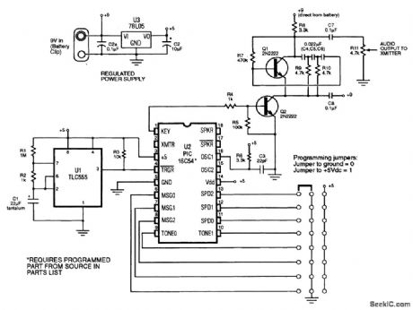
MORSE_MESSENGER
Published:2009/6/24 2:19:00 Author:May
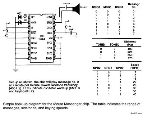
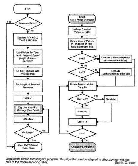
This keyer uses a PIC16C54 micro-controller to generate a Morse code message. The microcon-troller must be programmed to suit users call IC or desired message. (View)
View full Circuit Diagram | Comments | Reading(2086)
PASSIVE_MIXER
Published:2009/6/24 2:19:00 Author:May
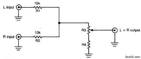
This simple circuit can be used to combine stereo signals to produce a mnaural output. R1 and R2 isolate both circuits and R3 controls the level of the combined output signal. (View)
View full Circuit Diagram | Comments | Reading(906)
CMOS_MIXER
Published:2009/6/24 2:13:00 Author:May
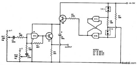
Four inputs can be mixed by duplicating the circuit to the left of C3 and using the fourth gate of IC1. Two gates are used in a touch-operated switching circuit that controls the voltage on the base of switching transistor Q2. Touching TP1 and TP2 alternately turns the circuit on and off. (View)
View full Circuit Diagram | Comments | Reading(784)
TWO_CHANNEL_PANNING_CIRCUIT
Published:2009/6/24 2:12:00 Author:May
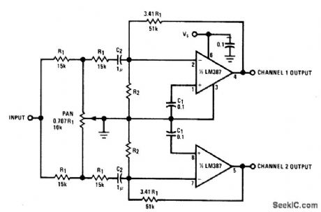
This panning circuit (short for panoramic control circuit) provides the ability to move the apparent position of one microphone's input between two output channels. This effect is oftern required in recording studio mixing consoles. Panning is how recording engineers manage to pick up your favorite pianist and float the sound over to the other side of the stage andback again. (View)
View full Circuit Diagram | Comments | Reading(2359)
HIGH_LEVEL_FOUR_CHANNEL_MIXER
Published:2009/6/24 2:07:00 Author:May
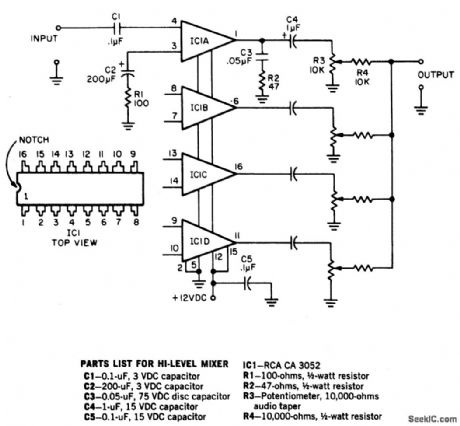
To provide good signal-to-noise ratio,this four channel mixer amplifier controls the signal levels after the amplifiers,and then mixes them to offer a combined output. The circuit works with any 50 ohm to 50 K dynamic microphone but not with crystal or ceramic mikes because the IC input impedance is low. Note that all four circuits are identical but that only one is shown complete. (View)
View full Circuit Diagram | Comments | Reading(1048)
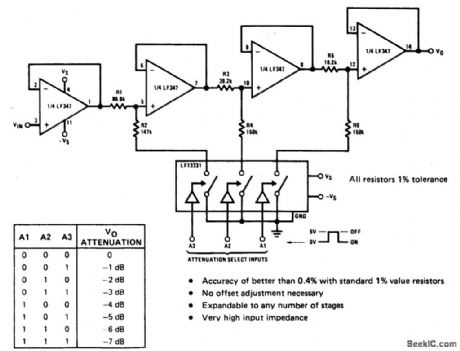
FOUR_INPUT_STEREO_MIXER
Published:2009/6/24 2:05:00 Author:May
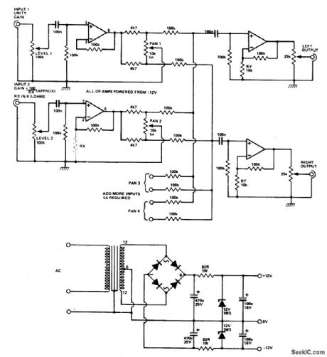
Four (or more) inputs can be mixed and produce stereo output. Gain of each stage can be boosted by adding RX, but it should be kept below 50 (RX above 2.2 K) to avoid poor fre-quency, response. If more than four stages are used, decrease RX to 6.8 K for six inputs, or 4.7 K for eight inputs. The op amps are 741 or other lower noise types. The power supply circuit is also given. (View)
View full Circuit Diagram | Comments | Reading(1008)
PROGRAMMABLE_ATTENUATOR_1_TO_00001
Published:2009/6/24 2:03:00 Author:May
View full Circuit Diagram | Comments | Reading(695)
VARIABLE_ATTENUATOR
Published:2009/6/24 2:00:00 Author:May
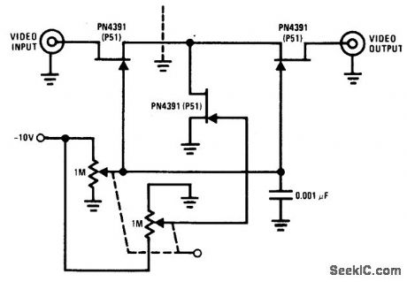
The PN4391 provides a low Rds(on) (less than 30 ohms). The tee attenuator provides for optimum dynamic linear range for attenuation and if complete turn-off is desired, attenuation of greater than 100 dB can be obtained at 10 MHz providing proper rf construction techniques are employed. (View)
View full Circuit Diagram | Comments | Reading(977)
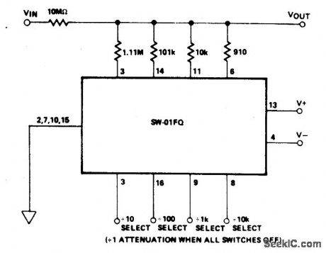
DIGITALLY_SELECTABLE_PRECISION_ATTENUATOR
Published:2009/6/24 1:58:00 Author:May
View full Circuit Diagram | Comments | Reading(822)
MELODY_CIRCUIT
Published:2009/6/24 1:56:00 Author:May
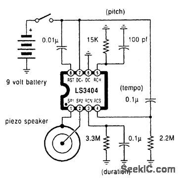
A high-quality melody circuit. The slow decay waveform produced will create chime-like notes. Pitch, tempo, and duration are all adjustable. (View)
View full Circuit Diagram | Comments | Reading(1336)
HV_REGULATOR_WITH_FOLDBACK_CURRENT_LIMIT
Published:2009/6/24 1:46:00 Author:May
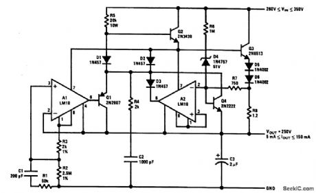
The output current issensed across R8, This is delivered to the current-limit arrtplifier through R7, across which the foldback potential is developed by R6 with a threshold determined by D4. The values given limit the peak power below 20 W and shut off the pass transistors when the voltage across them exceeds 310 V. With unregulated input voltages above this value, start-up is initiated solely by the current through R5. Q4 is added to provide some control on current before A2 has time to react.The circuit is stable with an output capacitor greater than about 2 μF. Spurious oscillations in current limit are suppressed by C2 and R4, while a strange, latch-mode oscillation coming out of current limit is killed with C1 and R1. (View)
View full Circuit Diagram | Comments | Reading(1294)
ONE_SHOT_MULTIVIBRATOR
Published:2009/6/23 22:34:00 Author:May
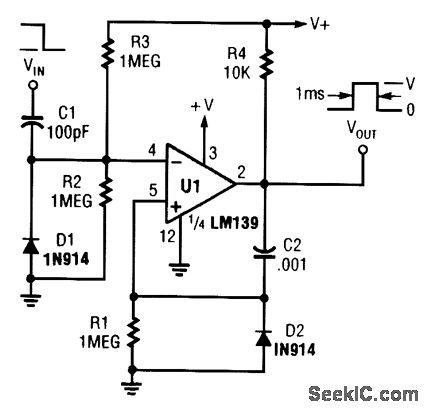
A section of a quad LM139 is used here as a one-shot pulse former. (View)
View full Circuit Diagram | Comments | Reading(0)
MULTIPLE_APERTURE_WINDOW_DISCRIMINATOR
Published:2009/6/23 5:07:00 Author:May

V1 through V4 are reference voltages that are derived from separate sources or from a com-mon voltage divider. (View)
View full Circuit Diagram | Comments | Reading(1)
VIDEO_MODULATOR_HOOKUP
Published:2009/6/23 5:06:00 Author:May
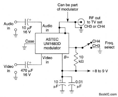
This circuit uses an ASTEC UM1683D,but it is typical of many RF video modulators used in VCRs and satellite receivers. (View)
View full Circuit Diagram | Comments | Reading(1843)
WINDOW_COMPARATOR
Published:2009/6/23 5:06:00 Author:May
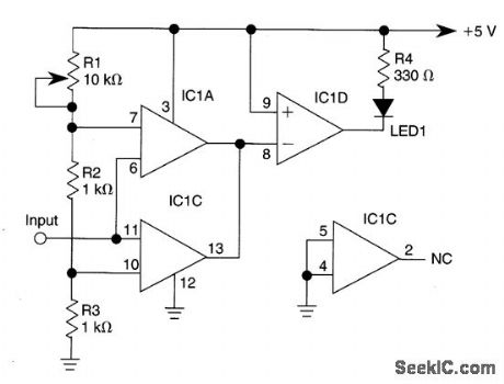
IC1-c functions as a noninverting compara-tor, and IC1-a operates as an inverting compara-tor. Potentiometer RI and fixed resistors R2 and R3 form a divider chain that delivers slightly dif-ferent voltages to the two comparators. These voltages define the upper and lower limits of the circuit's switching window, which can be changed easily by varying R2 and R3. The LED glows only when the input voltage falls within the window region. (View)
View full Circuit Diagram | Comments | Reading(0)
| Pages:13/24 1234567891011121314151617181920Under 20 |
Circuit Categories
power supply circuit
Amplifier Circuit
Basic Circuit
LED and Light Circuit
Sensor Circuit
Signal Processing
Electrical Equipment Circuit
Control Circuit
Remote Control Circuit
A/D-D/A Converter Circuit
Audio Circuit
Measuring and Test Circuit
Communication Circuit
Computer-Related Circuit
555 Circuit
Automotive Circuit
Repairing Circuit