
Analog Circuit
Index
High Voltage Stun Gun
Published:2013/7/17 21:36:00 Author:muriel | Keyword: High Voltage , Stun Gun
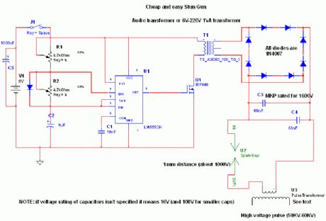
Read before building:This device produces high voltage pulses discrupting muscles and nervous sYstem, leaving anyone who touches it in a state of menthal confusion. Can be used agains ferocious animals or attackers, BUT REMEMBER, this device may be illegal in your state (for eg where I live, these devices are banned). It is quite dangeros for peoples experiencing cardiac problems, and for electronic equipment (like peacemakers), since it generates some RF. Don't attept irresponsible actions with this device, it is not a toy.
After the introduction let's pass to the circuit.The 555 IC is wired as a astable to produce square wave with adjustable freq and duty cycle (notice the potentiomenters and diode). This square wave is feed to a IRF840 Mosfet (no need of totem transistors since freq is low and the IC has enough current capability to rapidly charge/discharge the gate). As a substitute of the mosfet, a bipolar transistor can be used (and a 100ohm resistor between 555 and base of the transistor). Valid BJT can be BU406, but also smaller BJT can be ok, keep in mind that it must handle at least 2A continuous. The inductive kick snubber isn't needed because the power is low and it is almost totally adsorbed to charge the tank capacitor, in addition since this device is battery operated we don't want to dissipate the power on a resistor but we want it in sparks. With a snubbing network you will experience lower firing rates. USE A PUSHBUTTON SWITCH FOR SAFETYConstruction of T2: this is the real boring part. Since it is unlikely to find it in shops we need to build them. Materials needed: enamel copper wire (0,20 mm or 0,125 mm), ferrite stick, LDPE sheets (0,25 mm). Secure the ferrite stick with a layer of ldpe (polyethilene, as a substiture use electric insulating tape) and glue it (or tape it) Place 200-250 windings on the ldpe (even more windings if the stick is more than 1'), another ldpe layer, another 200-250 windings and so on to finally have 5-6 layers (approx 1000-1400 turns but even more doesn't hurt performance, but be careful for internar arcing that will ruin it). Insulate it again and place the primary winding, 15-20 turns of 1mm wire are just ok, too much windings (too mush resistance and inductance) will lead to smaller current and smaller spike in T2 secondary because of lower rise time,and too few will not saturate the core. I chosen MKP capacitors because they have low ESR and ESL (they are widely used in tesla coils as mmc capacitors).The spark gap can be simple two crossed (but not touching) 1 mm spaced wires. It acts as a voltage controlled switch, firing whenthe voltage is enough to ionize the air between them (turning it to plasma with small resistance). Keep in mind that it wouldbe wise do place it into a small plastic container and fill with oil letting bubbles out (don't use motor oir or frying oilbut pure mineral oil which has no water in it. (View)
View full Circuit Diagram | Comments | Reading(1722)
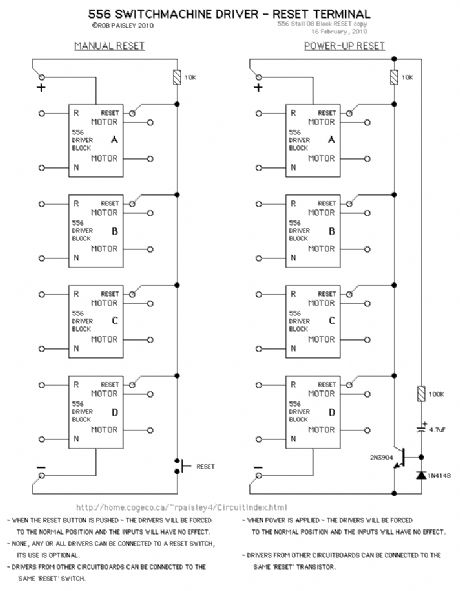
RESET terminal
Published:2013/6/5 22:02:00 Author:muriel | Keyword: RESET terminal
View full Circuit Diagram | Comments | Reading(790)
Bass and treble tone two-way control circuit diagram
Published:2012/12/20 2:19:00 Author:Ecco | Keyword: Bass , treble tone, two-way control
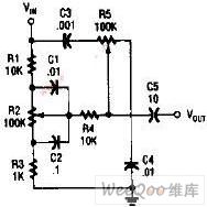
Bass and treble circuits are connected together to constitute two-way control tone control circuit shown in figure.
(View)
View full Circuit Diagram | Comments | Reading(2087)
The analog USB with homemade USB port ISP2313
Published:2012/8/23 22:54:00 Author:Ecco | Keyword: analog USB , homemade, USB port
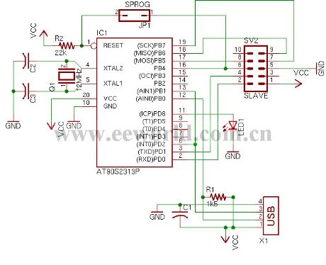
Many laptops have no serial or parallel port. In this case, people only can use the USB port ISP. The production is not using a real USB chip, but with 2313 to copy USB timing.
(View)
View full Circuit Diagram | Comments | Reading(1214)
Half-adder circuit
Published:2011/12/5 1:59:00 Author:Ecco | Keyword: Half-adder
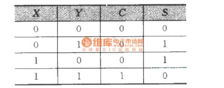
The valuetable:
(View)
View full Circuit Diagram | Comments | Reading(1192)
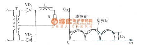
Single-phase full-wave rectifier inductance filter circuit
Published:2011/12/6 21:15:00 Author:Ecco | Keyword: Single-phase, full-wave , rectifier, inductance filter
View full Circuit Diagram | Comments | Reading(1033)
The typical application circuit of Darlington
Published:2011/12/1 2:17:00 Author:Ecco | Keyword: typical application circuit , Darlington
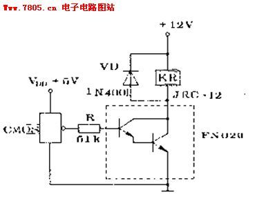
1. It is usedfor high-power switching circuits , motor speed adjusting and inverter circuit .2. It is used todrive a small relayItuses CMOS circuit Darlington circuit to drive high- sensitivity relay , and the circuit is shown in Figure 1. Thelow-power NPN Darlington FN020 is shown in dotted line block.
(View)
View full Circuit Diagram | Comments | Reading(1045)
The direct FM modulation circuit composed of varactor
Published:2011/12/2 1:48:00 Author:Ecco | Keyword: direct , FM modulation , varactor
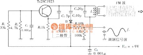
View full Circuit Diagram | Comments | Reading(1438)
The realization circuit of analog PWM circuit
Published:2011/11/1 21:24:00 Author:Ecco | Keyword: realization circuit , analog PWM circuit
View full Circuit Diagram | Comments | Reading(2631)
E305SCH modular amplifier circuit diagram
Published:2011/9/14 2:55:00 Author:Ecco | Keyword: modular amplifier
View full Circuit Diagram | Comments | Reading(1108)
The remote temperature measurement circuit composed of intelligent temperature sensor and external buffer
Published:2011/9/10 22:01:00 Author:Felicity | Keyword: remote temperature measurement circuit, intelligent temperature sensor, external buffer
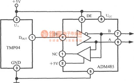
During the remote temperature measurement, TMP03/04 has a big advantage over analog output temperature sensor. It’s becausethe output is digital signal which has a better performance of resisting disturbance. The proportion of T1/T2 cannot be affected between long distance transmission and an AD485 type RS-485 differential line drive can be added if necessary as shown in the circuit diagram. This circuit can transmit temperature signal over 1200m. The time delay caused by emitter and receiver in ADM485 is 5ns and won’t affect T1, T2. (View)
View full Circuit Diagram | Comments | Reading(1010)
Temperatur/Frequency conversion circuit ( low power programmable integrated temperature controller TMP01)
Published:2011/9/10 22:00:00 Author:Felicity | Keyword: Temperatur/Frequency conversion circuit, low power, programmable , integrated temperature controller
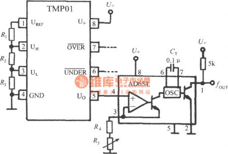
During long distance transmission, temperature signal can be converted into frequency signal and the circuit is shown in the figure. The AD654 voltage/frequency convertor (VFC for short) is adopted in the circuit which can suppress the noise disturbance and voltage fluctuation. When the precision of U/f conversion is enough, the output signal can stand for the test temperature which determined as follow. And CT is the capacity of the external timing capacitor of the internal oscillator. The frequency can be corrected by adjusting R5.
(View)
View full Circuit Diagram | Comments | Reading(1247)
Parallel output digital temperature transmitter circuit (integrated temperature sensor with voltage output LM35)
Published:2011/9/10 21:59:00 Author:Felicity | Keyword: Parallel output, digital temperature transmitter , integrated temperature sensor, voltage output

View full Circuit Diagram | Comments | Reading(1606)
Serial output digital temperature transmitter circuit (integrated temperature sensor with voltage output LM35)
Published:2011/9/10 22:01:00 Author:Felicity | Keyword: Serial output, digital temperature transmitter , integrated temperature sensor, voltage output
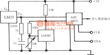
The output of LM35 is analog quantity and can get digital quantity output by A/D converter (ADC). A serial output digital temperature transmitter circuit with ADC08031 is shown in the figure and the range is +128℃ .The CLK and ENA in the figure are Clock terminal and Enable terminal.
(View)
View full Circuit Diagram | Comments | Reading(1733)
Output adapter circuit of LM35 series temperature sensor---- High precision 100 fields LED bar diagram display meter circuit
Published:2011/9/10 22:01:00 Author:Felicity | Keyword: temperature sensor, Output adapter circuit , High precision , 100 fields LED bar diagram display
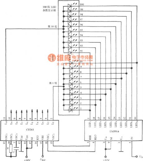
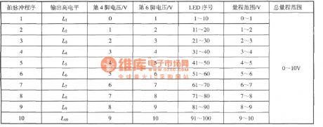
High precision 100 fields LED bar diagram display meter circuit is shown. This meter adapts the output circuit of LM35 series temperature sensor. For example, to build up a 0~10oC thermometer , the division value can be 0.1℃. The circuit contains CH261 and LM3914. The work program of LM3914: (View)
View full Circuit Diagram | Comments | Reading(1933)
Average temperature measurement circuit composed of AD590(accurate integrated temperature sensor with current output)
Published:2011/9/10 22:03:00 Author:Felicity | Keyword: Average temperature measurement circuit, current output, accurate integrated temperature sensor
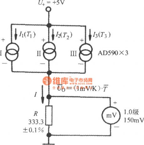


The figure shows the average temperature measurement circuit composed of AD590.The current through R is:.and the indication of the 1.0 millvoltmeter is the average temperature:i.e.Generally, assumed that the number test point is n and then the average temperature is:
(View)
View full Circuit Diagram | Comments | Reading(1457)
Diamond-shaped Bridge Analog Switched Circuit
Published:2011/9/3 10:27:00 Author:Zoey | Keyword: Diamond-shaped, Bridge, Analog Switched Circuit
Following picture refers to the diamond-shaped bridge analog switched circuit, this circuit can turn on and turn off analog signals that have a peak of 3v in 3ns. Symmetrical drive circuits can switch on and switch off quadruple transistor diamond-shaped bridge circuits with a clock frequency of 20MHz. Typical ascending time of 1-v direct current analog input signal is 1.5ns, descending time is 2ns. This circuit can meet the sampling-maintenance requirements of multiplex converter and pulse code modern remote-testing modulator that has a frequency of 100Mb/s. (View)
View full Circuit Diagram | Comments | Reading(1000)
Logic-control Analog Switched Circuit
Published:2011/9/3 10:30:00 Author:Zoey | Keyword: Logic-control, Analog Switched Circuit
The logic-control analog switched circuit has been shown in the following picture. This switched circuit adopts 2N4860 junction field effect transistor, so its conduction resistance is only 20Ωand the pinchoff drain current is small. Operational amplifier LM102 constitutes a voltage follower and plays an important role in buffering. S67800 voltage converter can drive the switched circuit if controlled by DTL and TIL level. (View)
View full Circuit Diagram | Comments | Reading(939)
Three-Port CMOS Voltage Regulator Equivalent Circuit
Published:2011/8/23 22:07:00 Author:Robert | Keyword: Three-Port, CMOS, Voltage, Regulator, Equivalent
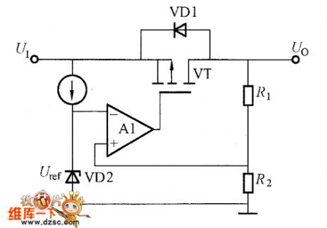
The three-port CMOS voltage regulator equivalent circuit is shown in the picture. Its internal control circuit is made up by the CMOS analog circuit. The output transistor uses the P-channel MOSFET (negatice output voltage uses N-channel MOSFET). The CMOS voltage regulator circuit's structure is simple. Many factories increase its performance by improving its manufacturing process. The CMOS voltage regulator's feature is that there are many products with low output voltage and low loading current, and they have low consumption current. They could be used as the power for charging the battery and local auxiliary power. (View)
View full Circuit Diagram | Comments | Reading(4194)
Typical application circuit of intelligent temperature controller MAX6641 based on SMbus
Published:2011/9/8 8:09:00 Author:Felicity | Keyword: intelligent temperature controller
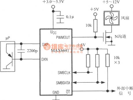
Typical application circuit of MAX6641 is shown in the figure. Using the PWMOUT terminal to drive N-MOSFET and to control the rotational speed of the pan. Remote PN junction temperature sensor can be replaced by the emitter of the triode inside micro processor (μP). Discrete component triode as CMPT3906、T3906、KST3906-TF、SMBT3906 etc. can also be adopted. Under the highest expected temperature and 10μA current the forward voltage drop of the emitter shall above 0.25V ; Under the lowest expected temperature and 100μA current the forward voltage drop of the emitter shall above 0.95V. High power triode shall not be adopted.
(View)
View full Circuit Diagram | Comments | Reading(1053)
| Pages:1/24 1234567891011121314151617181920Under 20 |
Circuit Categories
power supply circuit
Amplifier Circuit
Basic Circuit
LED and Light Circuit
Sensor Circuit
Signal Processing
Electrical Equipment Circuit
Control Circuit
Remote Control Circuit
A/D-D/A Converter Circuit
Audio Circuit
Measuring and Test Circuit
Communication Circuit
Computer-Related Circuit
555 Circuit
Automotive Circuit
Repairing Circuit