
Basic Circuit
Index 19
High And Low Voltage Cut Off With Time Delay 6
Published:2013/7/18 20:29:00 Author:muriel | Keyword: High And Low Voltage , Cut Off, Time Delay
View full Circuit Diagram | Comments | Reading(1286)
High And Low Voltage Cut Off With Time Delay 5
Published:2013/7/18 20:28:00 Author:muriel | Keyword: High And Low Voltage, Cut Off , Time Delay
View full Circuit Diagram | Comments | Reading(1499)
High And Low Voltage Cut Off With Time Delay 4
Published:2013/7/18 20:27:00 Author:muriel | Keyword: High And Low Voltage, Cut Off, Time Delay
View full Circuit Diagram | Comments | Reading(1098)
High And Low Voltage Cut Off With Time Delay 3
Published:2013/7/18 20:27:00 Author:muriel | Keyword: High And Low Voltage, Cut Off, Time Delay
View full Circuit Diagram | Comments | Reading(1313)
High And Low Voltage Cut Off With Time Delay 2
Published:2013/7/18 20:26:00 Author:muriel | Keyword: High And Low Voltage , Cut Off , Time Delay

View full Circuit Diagram | Comments | Reading(1110)
High And Low Voltage Cut Off With Time Delay
Published:2013/7/17 22:06:00 Author:muriel | Keyword: High And Low Voltage , Cut Off, Time Delay
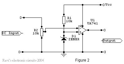
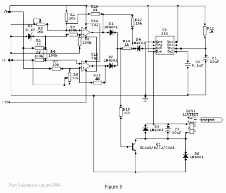
OverviewThe power line fluctuations and cut-offs cause damages to electrical appliances connected to the line. It is more serious in the case of domestic appliances like fridge and air conditioners. If a fridge is operated on low voltage, excessive current flows through the motor, which heats up, and get damaged.The under/over voltage protection circuit with time delay presented here is a low cost and reliable circuit for protecting such equipments from damages. Whenever the power line is switched on it gets connected to the appliance only after a delay of a fixed time. If there is hi/low fluctuations beyond sets limits the appliance get disconnected. The system tries to connect the power back after the specific time delay, the delay being counted from the time of disconnection. If the power down time (time for which the voltage is beyond limits) is less than the delay time, the power resumes after the delay: If it is equal or more, then the power resumes directly.This circuit has been designed, built and evaluated by me to use as a protector for my home refrigerator. This is designed around readily available semi-conductor devices such as standard bipolar medium power NPN transistor (D313/SL100/C1061), an 8-pin type 741 op-amp and NE555 timer IC. Its salient feature is that no relay hunting is employed. This draw back is commonly found in the proctors available in the market.The complete circuit is consisting of various stages. They are: - Dual rail power supply, Reference voltage source, Voltage comparators for hi/low cut offs, Time delay stage and Relay driver stage. Lets now look at the step-by-step design details.
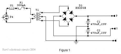
Dual rail power supply.This is a conventional type of power supply as shown in Figure 1. The power is applied through the step-down transformer (230/12-0-12V/500mA). The DC proportional to the charging input voltage is obtained from bridge rectifier. Two electrolytics are there to bypass any spikes present. Bridge is capable of handling currents up to 1 Amp.Output is given by: -V(out) = 0.71 X V (secondary)= 0.71 X 24V= 17.04 V(This equation is similar for the negative rail as well)
(View)
View full Circuit Diagram | Comments | Reading(1453)
High Voltage Stun Gun
Published:2013/7/17 21:36:00 Author:muriel | Keyword: High Voltage , Stun Gun
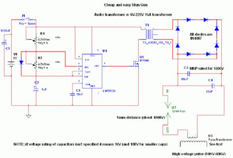
Read before building:This device produces high voltage pulses discrupting muscles and nervous sYstem, leaving anyone who touches it in a state of menthal confusion. Can be used agains ferocious animals or attackers, BUT REMEMBER, this device may be illegal in your state (for eg where I live, these devices are banned). It is quite dangeros for peoples experiencing cardiac problems, and for electronic equipment (like peacemakers), since it generates some RF. Don't attept irresponsible actions with this device, it is not a toy.
After the introduction let's pass to the circuit.The 555 IC is wired as a astable to produce square wave with adjustable freq and duty cycle (notice the potentiomenters and diode). This square wave is feed to a IRF840 Mosfet (no need of totem transistors since freq is low and the IC has enough current capability to rapidly charge/discharge the gate). As a substitute of the mosfet, a bipolar transistor can be used (and a 100ohm resistor between 555 and base of the transistor). Valid BJT can be BU406, but also smaller BJT can be ok, keep in mind that it must handle at least 2A continuous. The inductive kick snubber isn't needed because the power is low and it is almost totally adsorbed to charge the tank capacitor, in addition since this device is battery operated we don't want to dissipate the power on a resistor but we want it in sparks. With a snubbing network you will experience lower firing rates. USE A PUSHBUTTON SWITCH FOR SAFETYConstruction of T2: this is the real boring part. Since it is unlikely to find it in shops we need to build them. Materials needed: enamel copper wire (0,20 mm or 0,125 mm), ferrite stick, LDPE sheets (0,25 mm). Secure the ferrite stick with a layer of ldpe (polyethilene, as a substiture use electric insulating tape) and glue it (or tape it) Place 200-250 windings on the ldpe (even more windings if the stick is more than 1'), another ldpe layer, another 200-250 windings and so on to finally have 5-6 layers (approx 1000-1400 turns but even more doesn't hurt performance, but be careful for internar arcing that will ruin it). Insulate it again and place the primary winding, 15-20 turns of 1mm wire are just ok, too much windings (too mush resistance and inductance) will lead to smaller current and smaller spike in T2 secondary because of lower rise time,and too few will not saturate the core. I chosen MKP capacitors because they have low ESR and ESL (they are widely used in tesla coils as mmc capacitors).The spark gap can be simple two crossed (but not touching) 1 mm spaced wires. It acts as a voltage controlled switch, firing whenthe voltage is enough to ionize the air between them (turning it to plasma with small resistance). Keep in mind that it wouldbe wise do place it into a small plastic container and fill with oil letting bubbles out (don't use motor oir or frying oilbut pure mineral oil which has no water in it. (View)
View full Circuit Diagram | Comments | Reading(1722)
Inverter
Published:2013/7/15 20:25:00 Author:muriel | Keyword: Inverter
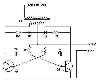
Have you ever wanted to run a TV, stereo or other appliance while on the road or camping? Well, this inverter should solve that problem. It takes 12 VDC and steps it up to 120 VAC. The wattage depends on which tansistors you use for Q1 and Q2, as well as how big a transformer you use for T1. The inverter can be constructed to supply anywhere from 1 to 1000 (1 KW) watts.
Parts:C1, C2 68 uf, 25 V Tantalum CapacitorR1, R2 10 Ohm, 5 Watt ResistorR3, R4 180 Ohm, 1 Watt ResistorD1, D2 HEP 154 Silicon DiodeQ1, Q2 2N3055 NPN Transistor (see Notes )T1 24V, Center Tapped Transformer (see Notes )MISC Wire, Case, Receptical (For Output)
Notes:1. Q1 and Q2, as well as T1, determine how much wattage the inverter can supply. With Q1,Q2=2N3055 and T1= 15 A, the inverter can supply about 300 watts. Larger transformers and more powerful transistors can be substituted for T1, Q1 and Q2 for more power.2. The easiest and least expensive way to get a large T1 is to re-wind an old microwave transformer. These transformers are rated at about 1KW and are perfect. Go to a local TV repair shop and dig through the dumpster until you get the largest microwave you can find. The bigger the microwave the bigger transformer. Remove the transformer, being careful not to touch the large high voltage capacitor that might still be charged. If you want, you can test the transformer, but they are usually still good. Now, remove the old 2000 V secondary, being careful not to damage the primary. Leave the primary in tact. Now, wind on 12 turns of wire, twist a loop (center tap), and wind on 12 more turns. The guage of the wire will depend on how much current you plan to have the transformer supply. Enamel covered magnet wire works great for this. Now secure the windings with tape. Thats all there is to it. Remember to use high current transistors for Q1 and Q2. The 2N3055's in the parts list can only handle 15 amps each.3. Remember, when operating at high wattages, this circuit draws huge amounts of current. Don't let your battery go dead :-).4. Since this project produces 120 VAC, you must include a fuse and build the project in a case.5. You must use tantalum capacitors for C1 and C2. Regular electrolytics will overheat and explode. And yes, 68uF is the correct value. There are no substitutions.6. This circuit can be tricky to get going. Differences in transformers, transistors, parts substitutions or anything else not on this page may cause it to not function.
(View)
View full Circuit Diagram | Comments | Reading(1089)
3 Line Mixer
Published:2013/7/15 20:19:00 Author:muriel | Keyword: 3 Line Mixer
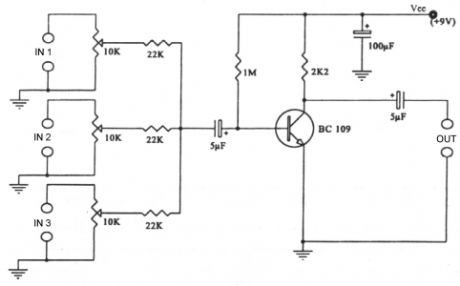
This project is a 3 or more lines mixer. For more than 3 inputs you can repeat the input parts (P=10K R=22K). It powered with 9Vdc.
(View)
View full Circuit Diagram | Comments | Reading(930)
Electronics Attenuator
Published:2013/7/15 20:18:00 Author:muriel | Keyword: Electronics Attenuator
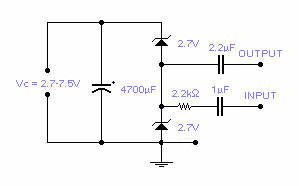
Two low voltage, low power zeners are used to control electronically the level of an audio signal. The attenuation range is from 6 to 58dB for an input current from 0.042 to 77 mA corresponding to a control voltage from 2.7 to 7.5V. If control voltage is limited to 5V, the attenuation is around 30dB at a control current of 2mA. This is not an HiFi attenuator but might come useful as a general purpose audio attenuator. (View)
View full Circuit Diagram | Comments | Reading(851)
Low pass filter - Subwoofer
Published:2013/7/15 19:57:00 Author:muriel | Keyword: Low pass, filter, Subwoofer
The acoustic spectrum is extended by very low frequencies 20Iz and reaches as the 20000Iz in high frequencies. In the low frequencies is degraded the sense of direction. This reason us leads to the utilization speaker for the attribution of very low frequencies. The manufacture that to you we propose distinguishes these frequencies, in order to him we lead to the corresponding amplifier. The acoustic filters are met in various points in the sound systems. The knownest application they are the filters baxandal for regulating tone low and high frequencies and filters crossover where the acoustic region is separated in subareas, in order to it leads the corresponding loudspeakers. The application that to you we propose is a simple filter of region that limits the acoustic region (20-20000Hz) in the region 20-100Hz.
With the manufacture that to you we propose you can make a active filter in order to you lead a loudspeaker of very low frequencies. With this you will place one bigger speaker between the HIFI speakers of you. In order to you have a complete picture of sound you will need also the corresponding amplifier. In the entry of circuit you will connect the two exits of preamplifier or the exit of line of some preamplifier. The circuit of manufacture allocates a exit in order to is led means of circuit of force subwoofer. If for some reason you do not have space in order to you place the third speaker in space of hearing, then you can select smaller speaker. The output will depend from the type of music that you hear. If in deed you have space, then after you make a filter and remain thanked, you can him recommend in your friends or still make other same for your friends.
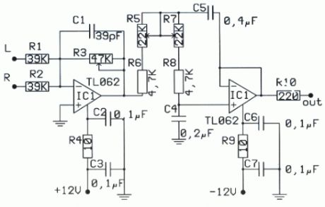
In the form it appears the theoretical circuit of filter. In first glance we see three different circuits that are mainly manufactured round two operational amplifiers. This circuits constitute mixed, amplifier with variable aid and a variable filter. The manufacture end needs a circuit of catering with operational tendency of catering equal with ±12. the operational amplifiers that constitute the active elements for this circuits of are double operational type as the TL082 and NE5532. The operational these amplifiers belong in a family provided with transistor of effect of field IFET in their entries. Each member of family allocates in their circuit bipolar transistor and effect of field. This circuits can function in his high tendency, because that they use transistor of high tendency. Also they have high honor of rhythm of elevation (slew rate), low current of polarization for the entries and are influenced little by the temperature. The operational these amplifiers have breadth of area unity gain bandwidth 3MHz. A other important element for their choice is the big reject of noise, when this exists in the line of catering.
The price of reject is bigger than 80dB, their consumption is small, from 11 until 3 mA. They are internally sold in nutshell with eight pins and allocate two operational amplifiers, In the same line in nutshell 14 pins they incorporate four operational, In the trade they are sold with code TL074, TL084 and TL064, In nutshell with eight pins they are sold operational amplifiers TL061 TL071 kajTL081. In the manufacture we used the TL082 that has two operational. First operational from the TL082 it works as amplifier and mixed for the two channels, In his negative entry he exists one small mixed with two resistances. A potentiometer in this rung determines the aid of circuit. In the point this left winger and the right channel of preamplifier they are added means of two resistances. En continuity the operational strengthens signal with aid made dependent from the price that has the potentiometer.
The place of runner is proportional with the aid of circuit. The second operational amplifier is the filter of manufacture. The filter of is acoustic frequency of second class and he is made with the materials that are round the operational amplifier. The filter of is low passage with variable frequency of cutting off. This frequency can be altered and take prices from very low frequency the 30Hz or still exceed 150Hz. The frequency of cutting off of filter depends from the prices that have the elements of circuit. Altering the values of elements we can have frequency of cutting off 150Iz, 130Iz, J00Iz, 7Ãz, 6Ãz even 3Ãz, this prices they can be achieved with the simple rotation of double potentiometer. The circuit of filter has been made around one operational' that it has completed TL082 that is double operational amplifier. In the exit of filter we will link the plug of expense where is connected the amplifier. In the exit of circuit is presented, the limited as for the breadth of frequencies, signal that we apply in the entry of circuit.
(View)
View full Circuit Diagram | Comments | Reading(1333)
Sound Level Indicator
Published:2013/7/15 19:54:00 Author:muriel | Keyword: Sound Level Indicator
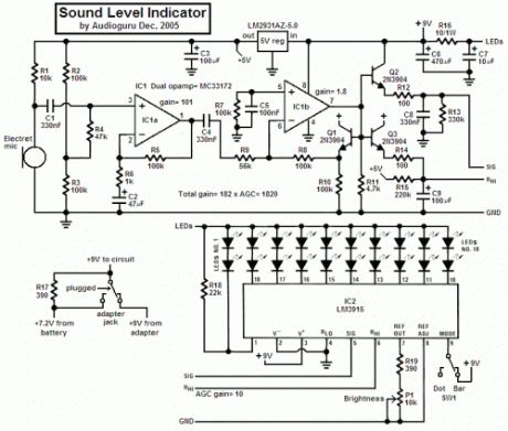
This project uses an LM3915 bar-graph IC driving two sets of ten LEDs for a 30dB range. The circuit is unique because it has an additional range of 20dB provided by an automatic gain control to allow it to be very sensitive to low sound levels but it increases its range 20dB for loud sounds.
The LEDs are operating at 26mA each with the brightness control at maximum, which is very bright. The circuit has a switch to select the modes of operation: a moving dot of light, or a bar with a changing length.My prototype has a little 9V Ni-Cad rechargeable battery in it to be portable and the battery is trickle-charged when the project is powered by a 9V AC-DC adapter.
Circuit Description1) The electret microphone is powered by and has a load of R1 from an LM2931 5V low-dropout regulator.2) The 1st opamp stage is an audio preamp with a gain of 101.3) The 2nd opamp stage is a single-supply opamp which works fine with its inputs and output at ground and is used as a rectifier driver with a gain of 1.8. It is biased at ground. Since it is inverting, when its input swings negative, its output swings positive.4) Three 2N3904 transistors are used as emitter-followers:a) Q1 is inside the negative feedback loop of the 2nd opamp as a voltage reference for the other two transistors. Hopefully the transistors match each other.b) Q2 emitter-follower transistor quickly charges C8 which discharges slower into R13 and is used as a peak detector.c) Q3 transistor is the automatic gain control. It is also a peak detector but has slower charge and discharge times. It drives the comparators’ resistor ladder in the LM3915 to determine how sensitive it is. R15 from +5V is in a voltage divider with the ladder’s total resistance of about 25k and provides the top of the ladder with about +0.51V when there is a very low sound level detected. Loud sounds cause Q3 to drive the top of the ladder to 5.1V for reduced sensitivity.5) The LM3915 regulates the current for the LEDs so they don’t need current-limiting resistors. In the bar mode with all LEDs lit then the LM3915 gets hot so the 10 ohm/1W resistor R16 shares the heat.
Options1) You could use a switch to change the brightness instead of a pot, or leave it bright.2) You could use an LM358 dual opamp (I tried it) but its output drops above 4Khz. The MC33172 is flat to 20kHz with this high gain.3) You could add a 1uF to 2.2uF capacitor across R5 so the indicator responds only to bass or “the beat†of music. Then an LM358 dual opamp is fine.
Construction1) The stripboard layout was designed for a Hammond 1591B plastic box with space in the lower end for a rechargeable 9V battery. One bolt holds the circuit board and a second bolt was cut short as a guide.2) A second piece of stripboard was used on a diagonal to space the LEDs closely together. A few LEDs needed their rim to be filed slightly to fit.3) A third piece of stripboard was used as a separating wall for the battery and it interlocks with the LEDs stripboard to hold it in place.4) 11-wire flexible ribbon cable connects to the LEDs.5) Use shielded audio from the microphone and a rubber grommet holding it.
(View)
View full Circuit Diagram | Comments | Reading(2215)
Dip Oscillator
Published:2013/7/15 1:01:00 Author:muriel | Keyword: Dip Oscillator
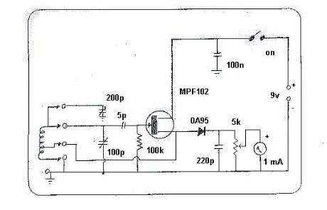
The unit features four plug-in coils for frequencies between 2.6 and 55 MHz. The coils are mounted on 12mm formers glued to 5-pin DIN plugs. A two gang, air dielectric variable capacitor (salvaged from an old radio) is used as the tuning control. The use of the smaller gang provides better bandspread at higher frequencies. The larger gang is connected when needed (lowest frequency band only). A vernier reduction drive on the variable capacitor makes the instrument easier and more pleasant to use. Wires should be kept short to ensure correct operation at higher frequencies.
In use the variable resistor is set so that the meter needle is near two-thirds scale. Bringing the coil close to a tuned circuit and adjusting the variable capacitor should result in a dip of the meter needle when the dip oscillator's tuned circuit and the tuned circuit under test resonate at the same frequency.
(View)
View full Circuit Diagram | Comments | Reading(1316)
500 WATT PA 2
Published:2013/7/15 0:57:00 Author:muriel | Keyword: 500 WATT PA

View full Circuit Diagram | Comments | Reading(994)
500 WATT PA 1
Published:2013/7/15 0:57:00 Author:muriel | Keyword: 500 WATT PA
View full Circuit Diagram | Comments | Reading(1745)
500 WATT PA
Published:2013/7/15 0:56:00 Author:muriel | Keyword: 500 WATT PA
Although I am an avid proponent of QRP (using reasonable power levels), there are times when I wish that I could run 1,000,000 watts and point it in a particular direction. If you are reading this then you know exactly what I am writing about. Unfortunately, here in the real world, it is quite expensive to buy or build BIG linear amplifiers - until now.
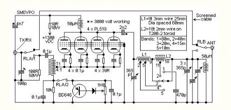
This is the circuit of a 500 watt linear amplifier, based upon a design by Frits Geerligs, PA0FRI, who has his own homepage at http://home.planet.nl/~fhvgeerligs. The circuit uses four PL519 TV line output valves in a very simple circuit that will deliver over 450 watts at 3.5 MHz (350 watts at 30 MHz). PL519 (40KG6A) is a more robust replacement for the earlier PL509 (40KG6) tube. Both valves will work well in this circuit. The input drive power is about 50 - 100 watts so it is compatible with most amateur radio HF transmitters. Not shown in the circuit is the cooling fan that is required to force air around the valves to cool them. In operation the 1K0 pot is adjusted to set the total valve anode current to around 50mA to 70 mA.
T1 is a 4:1 balun wound on a 5cm ferrite rod. 9 + 9 turns. Connect the end of the first winding to the start of the second to form the center tap.
L1 is 9 turns of 3mm Dia wire, wound on a 25mm Dia, 60mm long former.
L2 is 18 turns on a toroidal former. Use two length of 2mm Dia wire, one with 11 turns and the other with 7 turns.
The 50 watt 100 ohm resistor recomended by PA0FRI is formed by two 50 ohm 25 watt non-inductive TO-220 resistors in series, bolted beside the fan. I use 100 x 10K carbon resistors aranged 10 x 10 between two pieces of 0.1 matrix wiring board (veroboard). My method is cheaper and avoids the need to mount input circuitry above chassis. All inputs are kept below the chassis whilst the valve anode terminals and output circuitry is kept below the chassis. The 100pf trimmer capacitor is adjusted for best VSWR from the driving transmitter at 29 MHz.
All four valve heaters (40 volts each) may be wired in series and connected to the 220 volt mains via a 6uf 250vAC capacitor for 50 Hz (5uf for 60 Hz). I personally favour the use of a 40 volt transformer winding, on a home-made transformer, to run all the valves heaters (in parallel) as well as the 40 volt fan. This places less strain on the cathode/heater insulation of old tubes that may have been kicked around in junk boxes for years.
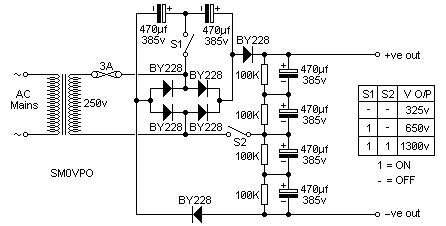
PA0FRI sugests a power supply circuit which is switcheable and delivers 325 volts, 650 volts or 1300 volts to the amplifier. The circuit is very clever, and shown below for your interest.
(View)
View full Circuit Diagram | Comments | Reading(1620)
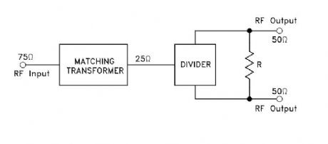
Input at 75Ω to Two Outputs at 50Ω
Published:2013/7/11 2:47:00 Author:muriel | Keyword: Input at 75Ω to Two Outputs at 50Ω
View full Circuit Diagram | Comments | Reading(755)
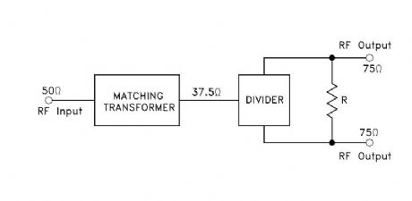
Input at 50Ω to Two Outputs at 75Ω
Published:2013/7/11 2:46:00 Author:muriel | Keyword: Input at 50Ω to Two Outputs at 75Ω
View full Circuit Diagram | Comments | Reading(708)
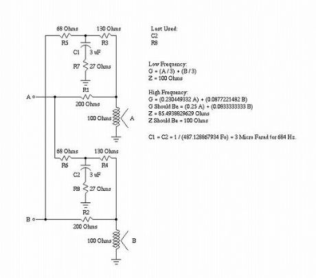
Passive Implementation
Published:2013/7/11 2:32:00 Author:muriel | Keyword: Passive Implementation
View full Circuit Diagram | Comments | Reading(829)
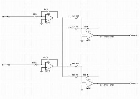
High Frequency Equivalent Circuit Schematic
Published:2013/7/11 2:32:00 Author:muriel | Keyword: High Frequency Equivalent Circuit Schematic
View full Circuit Diagram | Comments | Reading(921)
| Pages:19/471 1234567891011121314151617181920Under 20 |
Circuit Categories
power supply circuit
Amplifier Circuit
Basic Circuit
LED and Light Circuit
Sensor Circuit
Signal Processing
Electrical Equipment Circuit
Control Circuit
Remote Control Circuit
A/D-D/A Converter Circuit
Audio Circuit
Measuring and Test Circuit
Communication Circuit
Computer-Related Circuit
555 Circuit
Automotive Circuit
Repairing Circuit