
Basic Circuit
Index 15
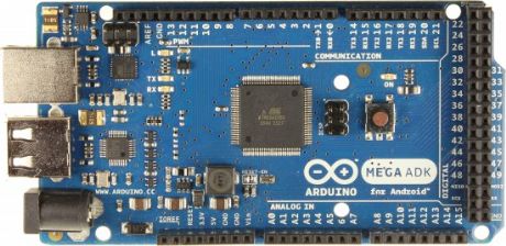
Arduino Mega ADK Pinout
Published:2013/9/29 20:00:00 Author:lynne | Keyword: Arduino Mega ADK Pinout
Input and Output
Each of the 50 digital pins on the Arduino Mega ADK can be used as an input or output, using pinMode(), digitalWrite(), and digitalRead() functions. They operate at 5 volts. Each pin can provide or receive a maximum of 40 mA and has an internal pull-up resistor (disconnected by default) of 20-50 kOhms.In addition, some pins have specialized functions:Serial: 0 (RX) and 1 (TX);Serial 1: 19 (RX) and 18 (TX);Serial 2: 17 (RX) and 16 (TX);Serial 3: 15 (RX) and 14 (TX).
Used to receive (RX) and transmit (TX) TTL serial data. Pins 0 and 1 are also connected to the corresponding pins of the ATmega8U2 USB-to-TTL Serial chip.
External Interrupts: 2 (interrupt 0), 3 (interrupt 1), 18 (interrupt 5), 19 (interrupt 4), 20 (interrupt 3), and 21 (interrupt 2). These pins can be configured to trigger an interrupt on a low value, a rising or falling edge, or a change in value. See the attachInterrupt() function for details.
PWM: 2 to 13 and 44 to 46. Provide 8-bit PWM output with the analogWrite() function.
SPI: 50 (MISO), 51 (MOSI), 52 (SCK), 53 (SS). These pins support SPI communication using the SPI library. The SPI pins are also broken out on the ICSP header, which is physically compatible with the Uno, Duemilanove and Diecimila.
USB Host: MAX3421E. The MAX3421E comunicate with Arduino with the SPI bus. So it uses the following pins:Digital: 7 (RST), 50 (MISO), 51 (MOSI), 52 (SCK).
NB: Please do not use Digital pin 7 as input or output because is used in the comunication with MAX3421E
Non broken out on headers: PJ3 (GP_MAX), PJ6 (INT_MAX), PH7 (SS).
LED: 13. There is a built-in LED connected to digital pin 13. When the pin is HIGH value, the LED is on, when the pin is LOW, it’s off.
TWI: 20 (SDA) and 21 (SCL). Support TWI communication using the Wire library. Note that these pins are not in the same location as the TWI pins on the Duemilanove or Diecimila.
The ADK has 16 analog inputs, each of which provide 10 bits of resolution (i.e. 1024 different values). By default they measure from ground to 5 volts, though is it possible to change the upper end of their range using the AREF pin and analogReference() function.
There are a couple of other pins on the board:
AREF. Reference voltage for the analog inputs. Used with analogReference().
Reset. Bring this line LOW to reset the microcontroller. Typically used to add a reset button to shields which block the one on the board. (View)
View full Circuit Diagram | Comments | Reading(1366)
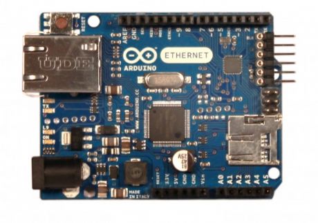
Arduino Ethernet Pinout
Published:2013/9/29 19:59:00 Author:lynne | Keyword: Arduino Ethernet Pinout
Input and Output
Each of the 14 digital pins on the Ethernet board can be used as an input or output, using pinMode(), digitalWrite(), and digitalRead() functions. They operate at 5 volts. Each pin can provide or receive a maximum of 40 mA and has an internal pull-up resistor (disconnected by default) of 20-50 kOhms.In addition, some pins have specialized functions:Serial: 0 (RX) and 1 (TX). Used to receive (RX) and transmit (TX) TTL serial data.
External Interrupts: 2 and 3. These pins can be configured to trigger an interrupt on a low value, a rising or falling edge, or a change in value. See the attachInterrupt() function for details.
PWM: 3, 5, 6, 9, and 10. Provide 8-bit PWM output with the analogWrite() function.
SPI: 10 (SS), 11 (MOSI), 12 (MISO), 13 (SCK). These pins support SPI communication using the SPI library.
LED: 9. There is a built-in LED connected to digital pin 9. When the pin is HIGH value, the LED is on, when the pin is LOW, it’s off. On most other arduino boards, this LED is found on pin 13. It is on pin 9 on the Ethernet board because pin 13 is used as part of the SPI connection.
The Ethernet board has 6 analog inputs, labeled A0 through A5, each of which provide 10 bits of resolution (i.e. 1024 different values). By default they measure from ground to 5 volts, though is it possible to change the upper end of their range using the AREF pin and the analogReference() function. Additionally, some pins have specialized functionality:
TWI: A4 (SDA) and A5 (SCL). Support TWI communication using the Wire library.
There are a couple of other pins on the board:
AREF. Reference voltage for the analog inputs. Used with analogReference().
Reset. Bring this line LOW to reset the microcontroller. Typically used to add a reset button to shields which block the one on the board.v (View)
View full Circuit Diagram | Comments | Reading(1167)
Arduino Pinout
Published:2013/9/28 21:10:00 Author:lynne | Keyword: Arduino Pinout
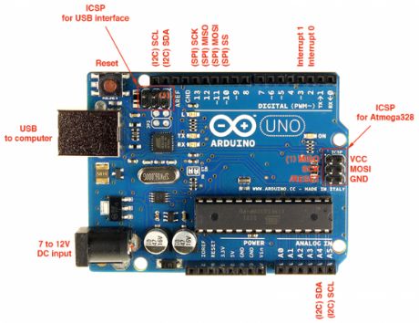
I myself own an Arduino Uno R3 and found that it can simplify my projects development and microcontroller programming, but sometimes I need to know the Arduino pinout. That is why I have written this article. There are many arduino boards with different pinouts. We will start with my favorite: Arduino Uno.
(View)
View full Circuit Diagram | Comments | Reading(1946)
LM2903, LM393 Datasheet
Published:2013/9/28 21:07:00 Author:lynne | Keyword: LM2903, LM393 Datasheet
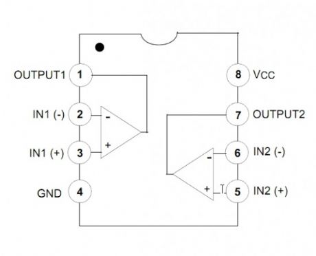
The LM2903, LM393/LM393A, LM293A consist of two independent voltage comparators designed to operate from a single power supply over a wide voltage range.LM393, LM2903 Features
Single Supply Operation: 2V to 36V
Dual Supply Operation: ±1V to ±18V
Allow Comparison of Voltages Near Ground Potential
Low Current Drain 800µA Typ.
Compatible with all Forms of Logic
Low Input Bias Current 25nA Typ.
Low Input Offset Current ±5nA Typ.
Low Offset Voltage ±1mV Typ.
(View)
View full Circuit Diagram | Comments | Reading(1800)
Vibration Impulse Counter
Published:2013/9/26 20:25:00 Author:lynne | Keyword: Vibration Impulse Counter

This is a take off from the previously posted bicycle anti-theft alarm. One commenter indicated a desire to adapt it to a threshold step plate vibration detector to count patrons entering a place of business. The circuit is now adapted for that application. Note that there are a myriad of other applications for this circuit.It consists of a piezoelectric film transducer, charge amplifier, charge pump detector, Schmitt trigger and counter driver. (View)
View full Circuit Diagram | Comments | Reading(1243)
LM3915 Circuit
Published:2013/9/26 20:24:00 Author:lynne | Keyword: LM3915 Circuit
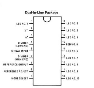
The LM3915 datasheet specifies that the IC is a monolithic integrated circuit that senses analog voltage levels and drives ten LEDs, LCDs or vacuum fluorescent displays, providing a logarithmic 3 dB/step analog display. One pin changes the display from a bar graph to a moving dot display. LED current drive is regulated and programmable, eliminating the need for current limiting resistors. The whole display system can operate from a single supply as low as 3V or as high as 25V.
LM3915 Features
3 dB/step, 30 dB range
Drives LEDs, LCDs, or vacuum fluorescents
Bar or dot display mode externally selectable by user
Expandable to displays of 90 dB
Internal voltage reference from 1.2V to 12V
Operates with single supply of 3V to 25V
Inputs operate down to ground
Output current programmable from 1 mA to 30 mA
Input withstands ±35V without damage or false outputs
Outputs are current regulated, open collectors
Directly drives TTL or CMOS
The internal 10-step divider is floating and can be referenced to a wide range of voltages (View)
View full Circuit Diagram | Comments | Reading(1485)
DIY Solar Tracker System
Published:2013/9/25 20:07:00 Author:lynne | Keyword: DIY Solar Tracker System
The solar panels are operating at optimal parameters when they are at the perfect right angle to the sun. Unfortunately this is accomplished only if solar panels are rotated by the sun. This is the purpose of this diy solar tracker system.
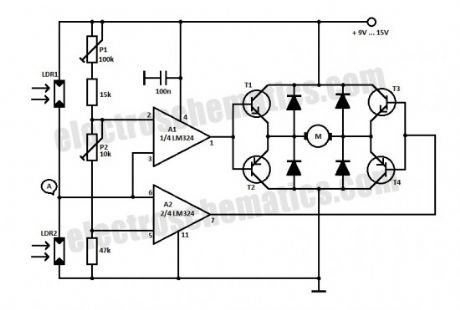
The solar tracker circuit uses a window comparator to maintain the motor in a idle state as long as the two LDRs are under the same illumination level. In this case, half the voltage is applied to the noninverting input of A1 and to the inverting input of A1.
solar tracking components
T1, T3 = BD239, BD139
T2, T4 = BD240, BD140
A1, A2 = 1/2 of LM324
Diodes = 1N4001
When the sun position is changing so does the illumination level on the LDRs and the input voltage for the window comparator is no longer half of the supply voltage thereby the output of the comparator generates informations for the motor that rotates the panels for tracking the sun.
P1 and P2 are adjusted in such way that the motor stands still when the LDRs get the same amount of solar light. If less light reaches LDR2 than LDR1, the voltage in point A increases to more than half of the power supply voltage. As a result the output of A1 is HIGH and T1 and T4 transistors conduct. In this situation the motor is starting.
If the angle of the solar light is changing again and the voltage in point A decreases at less than power supply voltage, the output of A2 goes HIGH and T3 and T2 transistors conduct. As a result the motor is rotating in opposite direction.
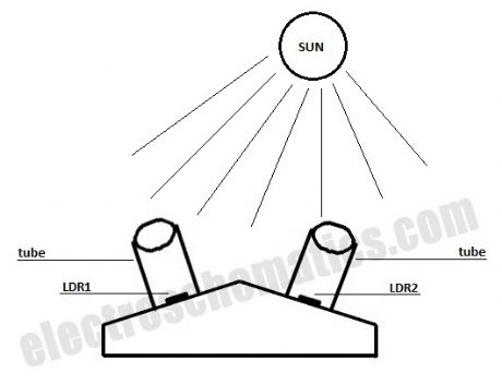
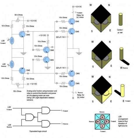
For solar panels control is best to use small motors with a suitable voltage and a maximum working current of 300 mA. This solar tracker system is used for tracking the sun only in one plane, the horizontal one. If you want to track the solar light in the vertical plane you need to build a separate sun tracker circuit.
This is a simple and practical analog solar panel tracker circuit. Using four LDR (light dependent resistor) as a sensor in detecting the light source arranged as illustrated. When the light hit the LDR in a certain position, it will activate the circuit and trigger the relay to turn the slewing motor in the right direction until the sensor is fully shaded under its cover stopping the motor to its rest condition. (View)
View full Circuit Diagram | Comments | Reading(3868)
DIY Water Softener System
Published:2013/9/25 20:03:00 Author:lynne | Keyword: DIY Water Softener System
Hard water has a high concentration of minerals, and of these calcium salts are the most troublesome. But there is a solution coming in form of a cheap diy water softener system built with the well-known 555 IC. Actually the price of this diy system is so low that even if this doesn’t work you won’t be upset.
The working principle of the water softener is based on a theory from 1930 which states that an electromagnetic or electric field causes small crystals of calcium carbonate in the water to join together to form larger crystals.
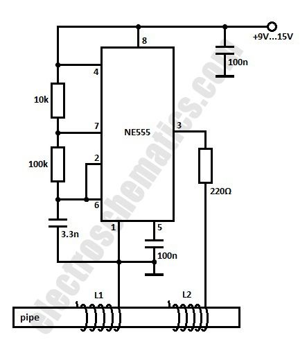
One of the methods to obtain a strong magnetic field is to put a powerful magnet (2.5 gauss) near the water pipe. The second method is the electronic one. Studying a water filter purchased from stores we found that it produces a frequency of about 15 kHz at an amplitude of 15V.
The values of the coils are not known, but my guess is L1 has 9 turns and L2 has 7 turns. Actually you should consider this circuit as a theoretical one.
Therefore this water softener system uses one 555 IC to obtain a rectangular signal that is applied to the water pipe by wrapping two coils with one open ending around it. The coils must have good isolation. Make sure to power the water softener from a isolated power supply because in some areas the water pipes are connected to ground. (View)
View full Circuit Diagram | Comments | Reading(1821)
1.5 Million x High Gain “Transistor”
Published:2013/9/24 20:36:00 Author:lynne | Keyword: 1.5 Million x High Gain “Transistor”
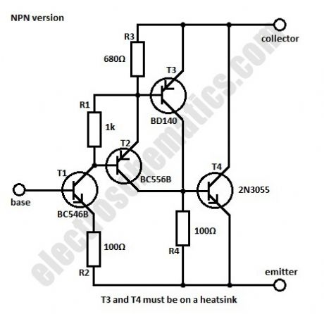


Sometimes we need a transistor with a different characteristic than the normal one for max voltage and current of the collector, maximum power dissipation and amplification. This can be done by using a combination of complementary transistors connected to work as a single NPN or PNP transistor.In the circuits given here we use four transistors for the NPN version of the high gain transistor and four the the PNP one. By choosing the best values for R1, R3 and R4 the total current amplification will be around 1.5 million. The characteristics of the circuit are essentially the same as the 2N3055 transistor.
At 25°C the maximum power dissipation can be up to 115 W while the maximum voltage of the collector is 60 V and max current is 15 A. The saturation voltage is 2 V for the NPN version and 3 V for the PNP one. (View)
View full Circuit Diagram | Comments | Reading(2435)
78XX Voltage Regulator Extension
Published:2013/9/24 20:33:00 Author:lynne | Keyword: 78XX Voltage Regulator Extension
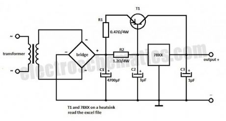
If the 78XX regulator and T1 are mounted on the same heat sink then the transistor is thermally protected. The output voltage is dependent only on the type of the voltage regulator used in the circuit. With the components presented in the schematic the maximum output current is 2 A. T1 is BD242 but for different values of the output current you need to replace some components (download the table at the end).
If higher values are necessary, some components must be changed according to the table presented in the excel file. For currents above 7 A then T1 must be replaced with 2 transistors (T1 and T1*) connected in parallel, each of them having a resistor in emitter, R1 and R1* respectively. Also the bridge rectifier is different. (View)
View full Circuit Diagram | Comments | Reading(1492)
Build Your Own Arduino Board
Published:2013/9/23 20:16:00 Author:lynne | Keyword: Build Your Own Arduino Board
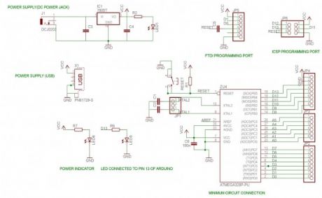
A brief introduction on the Atmega328 chip:
8-bit MCU
32kB Flash Memory
1kB EEPROM
2kB SRAM
23 general purpose IO lines
6-channel 10 bit ADC
SPI and I2C capabilities
(View)
View full Circuit Diagram | Comments | Reading(1405)
Soft Start for 12 Volt Halogen Lamps
Published:2013/9/22 19:52:00 Author:lynne | Keyword: Soft Start for 12 Volt Halogen Lamps
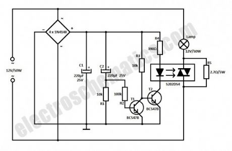
This simple 12 volt halogen lamp soft starter circuit extends the life of the halogen lamps by eliminating the sharp rise in the temperature of the filament; when the filament in cold it has a very low resistance.
How does the halogen soft start circuit works
The C2 capacitor is discharged when the lamp is turned on. As a result, T1 turns on, T2 is blocked and the optocoupler triac is not activated.The initial current for the filament heating is limited at a safe value of 4 A throught the R5 resistor that bypasses the triac.
In this time C2 is charging so that the voltage in the base of T1 begins to decrease. This transistor is blocked now so T1 starts to conduct. The LED inside the optocoupler triggers the triac and so the R5 resistor is practically short-circuited and the halogen lamp lights at maximum intensity.
The S202DS4 optocoupler must be mounted on a relatively big heatsink. The maximum current the the output is about 8 A.
(View)
View full Circuit Diagram | Comments | Reading(2693)
UM3763 Datasheet
Published:2013/9/21 21:09:00 Author:lynne | Keyword: UM3763 Datasheet
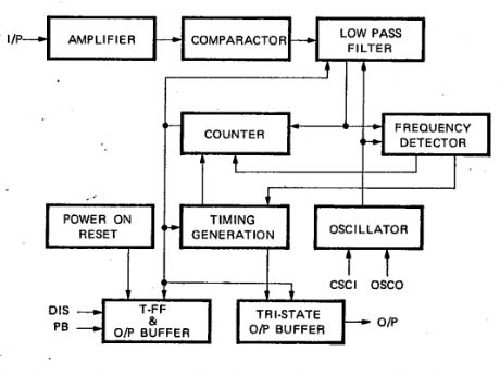
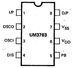
The UM3763 datasheet specifies that this IC is a CMOS LSI circuit which contains analog signal amplifiers and frequency detector for driving motor. It is designed for use in electronic devices and other applications. It is packed with 8 pins DIP.
UM3763 pin configuration
UM3763 features
typical 3V operating voltage
a motor can be driven by connecting a NPN transistor
RC oscillator with one external resistor
on-chip analog signal amplifiers
use of whistle for controlling
the output stage will change when the device senses effective frequency
(View)
View full Circuit Diagram | Comments | Reading(1414)
Appliance Remote Control Arduino Project Circuit
Published:2013/9/21 21:06:00 Author:lynne | Keyword: Appliance Remote Control Arduino Project Circuit
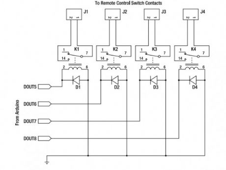
Starting from today I will try to post interesting Arduino projects from around the web. I am novice in this domain but I am giving my best to fully understant it.I must say from the begining that the projects are not developed by me and I will link the original source.This Arduino project uses a general-purpose appliance remote control that you can buy from a hardware store. It can be modified to link it to an Arduino for software control of devices around your house, without having to touch any mains-level wiring.
Parts required:
1 Arduino Duemilanove, Arduino Pro, Seeeduino, or equivalent
1 RF appliance remote control
1 Prototyping shield
4 5V reed relays
4 1N4001 power diodes or similar
4 PCB-mount male connectors
4 line-mount female connectors
10 cm ribbon cable
(View)
View full Circuit Diagram | Comments | Reading(980)
Auto No Break Power Supply Control
Published:2013/9/17 20:13:00 Author:lynne | Keyword: Auto No Break Power Supply Control
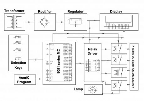
The major aim of this no break power supply project is to supply continuous energy supply to a load, by picking the supply from any spring out of the four like – generator, mains, inverter and solar robotically in the lack of any of the spring. The demand for power is raising day by day and regular electricity cuts are grounds to a lot of troubles in a range of areas such as- houses, hospitals and industries. A substitute arrangement for electricity supply is a must.
In this controller for no break power supply project 4 keys are there to display the particular breakdown of that power source. When out of the four any of the keys is pushed it confirms the lack of that exact spring, keys are linked to micro-controller as incoming signals. 8051 family’s micro-controller is brought into use. The productivity of micro-controller is set to the transmit driver IC, which controls suitable transmit to uphold continuous power supply to the load. The output has to be monitored by means of a lamp taking electricity supply from mains originally. On malfunctioning of the mains power supply (which is activated by pushing the suitable button) the load obtains power supply from the subsequent existing source, like an inverter.
If the inverter too stops working it turn over to the subsequent existing power source and so on. The electricity status, as to which power source delivers the load is also exhibited on an LCD. As it’s not possible to give all four different power springs of supply, one spring with swap switches are given to obtain the similar utility.
The no break power supply can in addition be improved by means of other springs such as wind speed power also and then taking into thought for bring into play the best feasible power whose duty maintains low at that point of time.
(View)
View full Circuit Diagram | Comments | Reading(1379)
Simple LED Tester
Published:2013/9/17 20:10:00 Author:lynne | Keyword: Simple LED Tester
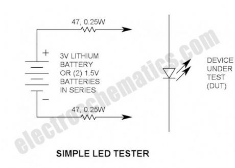
Do not let its extreme simplicity deceive you — this thing is useful! I have made many over the years and have even given some away as gifts. Yes multimeters have a Vf function, but mine barely lights a green, blue or white LED. This is especially useful in checking SMD LEDs that are very easy to otherwise get reverse. It may also be used to check a string of LEDs (one at a time) to make sure that all are installed correctly.
Why 3V?
3V is sufficient to turn on any LED, but is within its reverse break down voltage rating (that is why I did not use the common 9V battery). Short circuit current is approx. 30mA.
LED Tester Construction
I simply soldered (2) 47Ω, ¼W resistors to the two battery terminals and insulated the leads with Teflon tubing — PVC insulation stripped off wires will also work fine. I put a kink toward the end of the lead to keep the tubing in place. I have not had problems with the leads breaking — of course they will eventually fatigue and break, but it is a very simple repair — just avoid bending them sharply.
The battery
I used a 3V lithium battery that I salvaged from a circuit board. Good ones have a voltage that exceeds about 3V. Alternatives are the CR123 or DL123 photoflash battery—or you may simply tape two 1.5V AA or AAA batteries together and connect in series.
Soldering to battery terminals
Soldering directly to battery terminals can be risky. Sometimes it can damage the internal battery connection, so keep this in mind and be willing to sacrifice one in the process. My recommendation is to use a hot soldering iron to get it done quickly. Sometimes solder does not stick—in this case, carefully scrape the terminals with a knife to remove oxide and/or unfriendly plating.
Possible enhancements
How about making a single probe with stranded wires and a pair of spring-loaded test pins?
Storage
I keep mine in a small plastic “jewel case” to prevent accidental discharge.
(View)
View full Circuit Diagram | Comments | Reading(1192)
Resistors in Series
Published:2013/9/16 22:14:00 Author:lynne | Keyword: Resistors in Series

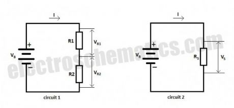
In this article we are talking about the resistors in series, how to calculate the equivalent resistance and about the voltage divider. Consider the following picture:
In circuit 1 we have 2 resistors R1 and R2 connected in series and in circuit 2 is shown the equivalent resistor Rs. I is the current that flows through the resistors and VB is the voltage of the battery or power supply. (View)
View full Circuit Diagram | Comments | Reading(924)
Resistors in Parallel
Published:2013/9/16 22:12:00 Author:lynne | Keyword: Resistors in Parallel
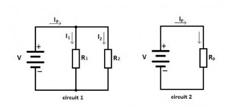
In this article we talk about resistors in parallel, the equivalent resistance and the current divider rule for parallel connection of resistors. Let’s consider this circuit:
In circuit 1 we have two resistors R1 and R2 connected in parallel and in circuit 2 the equivalent resistance Rp. I is the total current, I1 is the current that flows through R1 and I2 is the current that flows through R2. (View)
View full Circuit Diagram | Comments | Reading(1081)
Flashing Lamp like a Beacon Project Kit
Published:2013/9/15 21:43:00 Author:lynne | Keyword: Flashing Lamp like a Beacon Project Kit

This flashing lamp project is intended to present flash lanterns/lamp creating a flare light by and large brings into play in ship yards, sea beaches etc. It’s also brought into play in center of the deep ocean to caution ships regarding the unseen rocks.
From 8051 family a programmable micro-controller is fit into place to supply the flash light at regular gaps according to the practice pursued at sea coast, ship yards etc. A small electrical energy lantern/lamp of 12Volts is fitted by a power MOSFET in Pulse width modulation (PWM) mode which itself is obtained from a micro-controller.
The task rotation of the Pulse width module has to be altered depending on the kind of purpose. Since the micro controller provides only 5volts drive, it’s not achievable for the MOSFET to be unfailingly change ON at that volt. A crossing point transistor is made use of amid the controller production and the MOSFET for forcing the same. (View)
View full Circuit Diagram | Comments | Reading(1070)
Battery Level Indicator for 24 Volts Batteries
Published:2013/9/15 21:41:00 Author:lynne | Keyword: Battery Level Indicator for 24 Volts Batteries
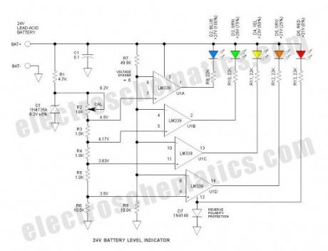
D1 is the voltage reference zener. Tied to this is a string of divider resistors (R2-6) that set the various fixed voltage levels. R7 & 8 form a voltage divider to that divides the battery voltage by a factor of 6. U1 is an LM339 quad comparator that compares the various voltages from the two dividers. The comparator sections have open collector outputs that simply function as switches to operate the LEDs. D7 protects against reverse battery connection.
The LM324 op amp should work OK, but the pin-out is different—and (4) LM741 op amps should also work OK.
It worked as expected and when R2 is calibrated properly, the voltage thresholds are within about 0.1V of stated values. There is no hysteresis so the LEDs tend to flicker slightly at the threshold voltages—this is not a problem.
The LEDs are biased to operate at about 1mA which is reasonably bright if high efficiency LEDs are used—mine were not of the high efficiency type. This current can be adjusted simply by varying the series resistors (R9 through R13). The overall current drain as shown is about 12mA with all the LEDs illuminated. To reduce power, a push-to-test pushbutton is recommended. (View)
View full Circuit Diagram | Comments | Reading(1985)
| Pages:15/471 1234567891011121314151617181920Under 20 |
Circuit Categories
power supply circuit
Amplifier Circuit
Basic Circuit
LED and Light Circuit
Sensor Circuit
Signal Processing
Electrical Equipment Circuit
Control Circuit
Remote Control Circuit
A/D-D/A Converter Circuit
Audio Circuit
Measuring and Test Circuit
Communication Circuit
Computer-Related Circuit
555 Circuit
Automotive Circuit
Repairing Circuit