
Basic Circuit
Index 16
Industrial Power Controller without Harmonics
Published:2013/9/11 20:45:00 Author:lynne | Keyword: Industrial Power Controller without Harmonics
The industrial power controller project is intended to attain vital cycle switching; a technique to get rid of complete cycle, cycles or fractions of cycles of an AC sign. It is a renowned and aged technique of managing AC power, principally across linear loads for instance heaters brought into play in electric oven.
On the other hand, the idea of attaining the cycle lifting of voltage waveform by bringing into use microcontroller which is of 8051 family can be extremely exact as per the plan engraved in assembly or C language so that the real time average voltage or electric current practiced at the load is fairly lesser than the entire signal if functional to the load. In position of a linear load to be employed in the output, a succession motor or lamp can be applied to make sure the output. One sided outcome of making use of this proposal is an unevenness in the input of the electric current or voltage waveform as the cycles are turned ON or OFF as per the load. (View)
View full Circuit Diagram | Comments | Reading(1144)
Power Control for Induction Motor
Published:2013/9/11 20:28:00 Author:lynne | Keyword: Power Control for Induction Motor

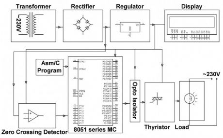
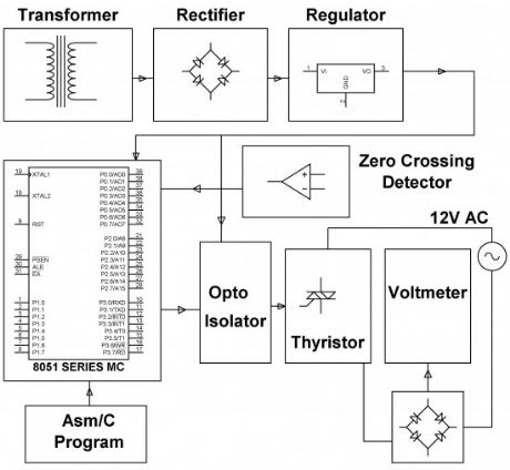
This induction motor power controller project is intended to manage AC power to a load by bringing into play sacking angle direct of thyristor. Effectiveness of such power control is extremely soaring in comparison to any other technique.
This AC power control project brings into play zero crossing end of the waveform which is discovered by a comparator whose productivity is then supplied to the micro-controller from 8051 family. The micro-controller makes available essential postponed trigger control to a couple of SCRs in the course of opto isolator interface. As a final point the power is applied to the load all the way through the SCRs in sequence.
(View)
View full Circuit Diagram | Comments | Reading(1349)
SCR Phase Control Dimmer Circuit
Published:2013/9/10 19:51:00 Author:lynne | Keyword: SCR Phase Control Dimmer Circuit
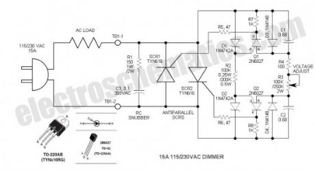
This SCR phase control works much like the common TRIAC dimmer, but has numerous advantages including increased current capability, robustness and absence of minimum voltage “snap-on.” A complementary, symmetrical trigger circuit consisting of two PUTs (programmable unijunction transistors) enables firing of two anti-parallel THYRISTORs (SCRs). The circuit makes up a two terminal power device that is simply inserted between the AC power source and load. Besides controlling the intensity of incandescent lighting, it is useful in controlling the speed of universal (commutator brush type) AC motors.
The DIAC is a 28V bidirectional (bilateral) trigger device that is used on virtually all inexpensive phase controls. The trigger voltage is somewhat high for phase control of 115VAC. Years ago, there was a similar low voltage (6 to 8V) trigger device called a Shockley diode. Unfortunately, these never caught on and today are EXTINCT.
The 2N6027 Programmable Unijunction Transistor (PUT) can perform a similar function, but is polarity sensitive so it does not lend itself to TRIAC control. However, if two such PUT trigger circuits are employed for anti-parallel SCRs, some interesting things are apparent. Most important is the ability to control both trigger circuits with a single potentiometer so that both half-cycles are controlled identically. To obtain best balance, the zeners and capacitors must be matched. Both zeners and capacitors are specified for a tolerance of 5%, but I selected mine for better than 1% with my DMM. Purchase a few additional components so that you may obtain a good match.
PUT operation is simple. Its threshold voltage is programmable so that it can trigger at low voltages. In this circuit it is set via the 12V zeners. When the PUT anode voltage exceeds the gate voltage by one junction drop, the PUT fires and dumps the timing capacitor into the SCR gate circuit. It resets when the AC line voltage reverses. (View)
View full Circuit Diagram | Comments | Reading(3004)
Delayed Automatic Power OFF
Published:2013/9/5 19:57:00 Author:lynne | Keyword: Delayed Automatic Power OFF
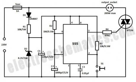
This circuit is build with the 555 IC and will automatically turn off the power after 20 minutes. You can use the circuit to turn off the porch light after you lock the house or similar other uses.The 555 timer is operated as a monostable and a momentary push on S1 switch makes the output go high which triggers the triac and makes power available in the socket.
The IC output goes low again when C2 has charge up to 2/3 of the supply voltage. This process takes about 20 minutes. C2 should have low leakage otherwise it will charge very slowly and in cases of excessive leakages may not charge to full value at all. Power supply for the timer is provided by half wave rectifier D1, voltage dropping resistor R1, zener diode D2 and filter capacitor C1.
(View)
View full Circuit Diagram | Comments | Reading(2319)
RC Servo Tester with 555 IC
Published:2013/9/2 20:53:00 Author:lynne | Keyword: RC Servo Tester with 555 IC
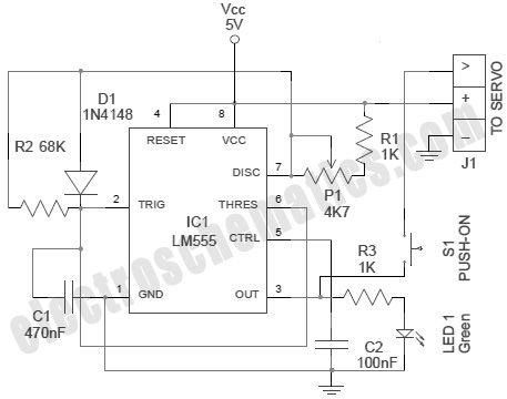
RC Servos basically come in three different sizes (micro, standard, and giant) to accommodate the type of RC models they are being used in. All RC servos have a three wire connector. One wire supplies positive DC voltage (usually 5 V) . The second wire is for voltage ground (0V), and the third wire is the signal (control) wire.
The servo motor can be moved to a desired angular position by sending PWM (pulse width modulated) signals on the signal (control) wire.Usually, a pulse of width varying from 1 millisecond to 2 milliseconds in a repeated time frame is sent to the servo for around 50 times in a second. The width of the pulse determines the angular position.
For example, a pulse of 1 millisecond moves the servo towards 0°, while a 2 milliseconds wide pulse would take it to 180°. The pulse width for in between angular positions can be interpolated accordingly. Thus a pulse of width 1.5 milliseconds will shift the servo to 90°. It must be noted that these values are only the estimations. The practical range of pulse width is 0.2ms to 2.5ms, and frequency is 20Hz to 60Hz.
Notes
Prototype was tested with a “Tower Pro Micro Servo”. Servo test socket “J1” in the circuit is a standard 3-pin male header. In case of any difficulty, you can use 3 flying leads with alligator clips as test probes
S1 is a “Push-To-On” switch works as a “Test Switch”
LED 1 is added to indicate the output status of the tester
Try to use a precision 4K7 trimpot as P1
Note that, here the control pulses have a maximum voltage near-equal to the input voltage (5V) of the tester circuit. This can be a problem if your servo expects a 3V control signal
It is good to add a 100µF/16V capacitor, as a buffer, across the 5V DC supply (VCC & Ground)
Change the values of R1, P1, R3 and C2 if necessary/when demanded by the RC Servo under test. Before testing an RC servo, carefully refer its technical datasheet (View)
View full Circuit Diagram | Comments | Reading(2363)
PCB Drill Speed Controller with 555 Circuit
Published:2013/9/2 20:48:00 Author:lynne | Keyword: PCB Drill Speed Controller with 555 Circuit
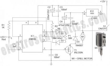
Described here is a simple, inexpensive and useful circuit for electronics hobbyists. The circuit is nothing but a PCB drill speed controller, which can be used to control the speed of any 12VDC small pcb drilling units. Such portable units are now widely available, and even a hobbyist can make it without too much difficulty.
In this circuit, the renowned timer chip LM555 (IC1) is used as a PWM circuit. The whole circuit can be powered from a standard 12VDC supply, capable of sourcing ample current to the PCB drill motor. As you may noted, power supply for the PWM circuit is down-converted and regulated with the help of a 3-pin fixed regulator chip LM7805 (IC2). This will improve the circuit stability. Precision 50K trimpot P1 is the variable drill speed controller. Finally, a logic-level power Mosfet IRL 530N (T1) is used as the output drive element. This IRL530N mosfet (available in TO-220 package) can handle current upto 27A! Fast switching and Low on-resistance – RDS (on) – are other attracting features. IRL 530N is universally preferred for all commercial-industrial applications at power dissipation levels to approximately 50 watts.
Drill Speed Controller Notes
PWM (Pulse Width Modulation) is an efficient way to vary the speed and power of electric DC motors. The described circuit can be used to vary the speed of small electric PCB drill.The circuits can quite easily be built on a standard prototyping board. The power component (IRL510N) must be connected to the power rails and the drill motor with quite thick wires and cables.As used here, a Power MOSFET motor driver is better than the traditional driver because it is working at a higher switch frequency, and this also avoids the unnecessary voltage drop and power loss
Electrically a DC motor can be viewed as a series RL network with a voltage generator. The generator represents the back electromotive force (BEMF) generated by the motor’s rotation and which opposes the electromotive force of the supply. Diode D3 (1N4007) is added to protect the electronics from BEMF. Diode “MBR 1645” is a better alternative
STP22NE10L (100V/<0.085R/22A) can be used in lieu IRL510N (100V/0.10R/17A)
12VDC /2A powered prototype tested with a 12V (1A) Small PCB Drill Press (View)
View full Circuit Diagram | Comments | Reading(1851)
Industrial Battery Charger Project Kit Circuit
Published:2013/9/1 20:49:00 Author:lynne | Keyword: Industrial Battery Charger Project Kit Circuit
The assignment is intended for charging battery(s) by DC from AC supply of power. DC power supplied for a battery’s charger is a derivative from a thyristor controlled rectifier mechanism. AC supply of power is useful to a link rectifier consisting of diodes and a TRIAC achieving preferred power from the micro controller.
This assignment of industrial battery charger brings into use zero crossing point of the waveform which is sensed by a comparator whose productivity is then supplied to the micro controller. The micro controller endow with necessary delay in triggering control to a TRIAC via opto isolator edge. As a final point the power is supplied to the load via triac in succession with the linking rectifier. The DC output which is rectified and controlled is provided to the load i.e., a resistor employed in our project as a substitute of a battery. The DC voltage thus produced is calculated by utilizing a multi-meter. In this industrial battery charger project we have used a microcontroller which is from 8051 family which is edged via push button keys employed for rising or lessening the DC voltage for appropriate charging reasons.
This particular project can be improved further by employing direct 230 volt power supply rather than 12 volt AC to the linked rectifier for obtaining high voltage to control for charging numerous of batteries connected in a sequence. (View)
View full Circuit Diagram | Comments | Reading(1234)
Electronic Key Circuit
Published:2013/8/30 2:15:00 Author:lynne | Keyword: Electronic Key Circuit
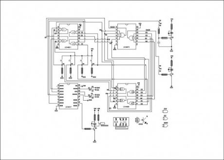
Based on CD4017 and logic gates this electronic circuit switches on a relay if you press four keys in the correct sequence, and backs to the start condition by pressing any key. Once the circuit is supplied the first output of the counter is on and sends the high signal to one input of the CD4081 first gate.By pressing the correct key (P1) the other input of that gate gets on. So pin 3 of the CD4081, then pin 1 of the CD4072 turns on the clock relay K1. The capacitor keeps on the relay for about 0,5 seconds and the key should not be pressed for a longer time.
When all keys are pressed in the correct order the relay K3 turns on. If you press a wrong key the inputs of the related EXOR gate of the CD4030 get a different signal, then the output turns on the reset relay K2 by pin 13 of the CD4072.
(View)
View full Circuit Diagram | Comments | Reading(1245)
Arduino Based Part Fill Automatic Valve
Published:2013/8/28 1:30:00 Author:lynne | Keyword: Arduino Based Part Fill Automatic Valve
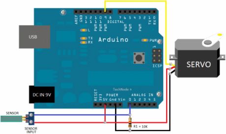
Wanna learn more about the Arduino platform? If you have an irresistible temptation to do some experiments using Arduino microcontroller, just try this simple “electronic” version of a “part fill” valve, wired using an Arduino, a standard hobby servo, and a home-made water sensor. When the Arduino notices the water level inside the rainwater tank is very low , it commands the servo to let the water flow from an alternate source!
Download/copy the simple sketch (Arduino program) included here, verify and upload it to the Arduino board with the help of the Arduino IDE. Here two pieces of stiff wire is used to sense the conductivity in the gap between the water sensor points. When there is more water, there is a higher conductivity. Arduino reads this conductivity, and at the level set by the sketch, turns the servo to release or constrict the flow of water. Needless to say, you should make your own water sensor pad using short-length of closely spaced wires, needles or solder pads. Besides, little skill and patience required to hook up the servo horn with the existing/new valve. The servo horn should crook the town mains water inlet valve open/close to control the flow of water. Zip ties can be used to secure the mechanical connection. Once in situ, try to hot glue the servo. (View)
View full Circuit Diagram | Comments | Reading(1173)
Automatic Fan Controller
Published:2013/8/28 1:26:00 Author:lynne | Keyword: Automatic Fan Controller
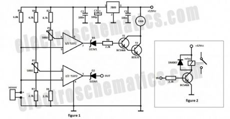
The automatic fan controller circuit shown in the schematic has 2 comparators with different triggering points that are independently adjustable. LM135 or LM335 in a TO92 package is used as a temperature sensor.
The R5 resistor polarizes the temperature sensor. On the non-inverting input of TL072 is applied a voltage that varies according to the temperature with 10mV/K. R1, R2, P1 and R3, R4, P2 form 2 resistive dividers whose voltage is applied on the inverting inputs of both comparators. Adjustment of the threshold point is done with P1 and P2.
When the non-inverting input voltage exceeds the threshold point (set by P1 and P2) the TL072 goes from Low to High state. The first comparator drives the fan motor with help from 2 transistors (T1 and T2) connected in a Darlington configuration as long as the temperature read by the sensor is higher than the level set with P1.
The threshold level of the automatic fan controller is made with a thermometer. Place the sensor on the surface which temperature you want to monitor. Read the temperature with the thermometer and adjust the threshold level of the fan with P1 at the desired temperature.
The second comparator goes from Low to High state when the threshold level adjusted with P2 is exceeded. You can connect a relay on the OUT output (using the circuit from figure 2) to disconnect or connect a second fan or other type of equipment.
You can connect a red LED in series with one 1kΩ resistor to signals when it reached the desired temperature.
(View)
View full Circuit Diagram | Comments | Reading(1856)
Ultrasonic Dog Repeller Circuit
Published:2013/8/27 2:29:00 Author:lynne | Keyword: Ultrasonic Dog Repeller Circuit
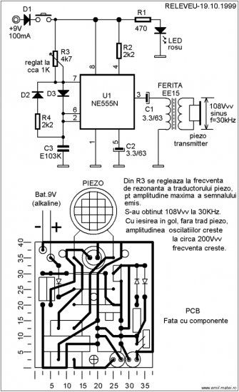

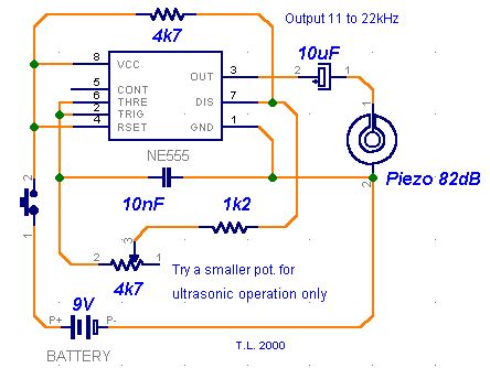
This ultrasonic dog repeller circuit will chase away angry dogs. It is build with the all known 555 circuit, a buzzer and a little ferrite transformator. The ultrasonic frequency must be set with a dog nearby.
Circuit number 1 uses the well known NE555 IC, couple of components and a EE15 ferrite transformer. Adjust R3 at resonance frequency of the piezo transducer for maximum aplitude of the repeller ultrasonic sound. At 30 KHz this can reach a value of 108 Vpp. Without the piezo the output voltage is around 200 Vpp.
(View)
View full Circuit Diagram | Comments | Reading(4146)
PIC12F635 Based Door Alarm System
Published:2013/8/22 20:15:00 Author:lynne | Keyword: PIC12F635 Based Door Alarm System
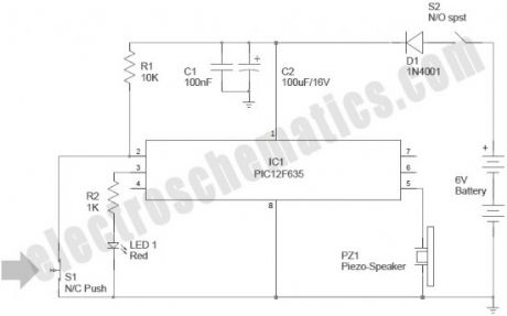
Now you can build your own simple door alarm security system using a tiny microcontroller chip PIC12F635! The circuit is nothing but an aural alert unit, which raises a warning tone when the concerned door is opened by someone. You can install this unit in your front/back door as a security alarm to deter burglars and intruders.The unit can be powered from four 1.5V AA/AAA cells wired in series (6VDC).
After construction and testing, carefully mount switch S1 in the door (or doorcase) so that it is in “open” condition when the door is in closed state. Next, set up the alarm unit at a remote location, and make the interconnection between S1 and the alarm unit using low-voltage cables.
The circuit can be energized by turning the power switch S1 to “On” position. The Red LED (LED1) blinks 3 times when the power is turned on to indicate that the system has been powered up. Then IC1 (PIC12F635) waits for 30 seconds before it starts monitoring the door sensor (S1) status. This delay is introduced deliberately to help the user to “arm” the alarm and move out through the door without triggering the alarm system. After this initial delay, when the IC1 detects S1 is closed (door opened) , it drives the iezo – speaker (PZ1) with a square wave signal, and the piezo – speaker remains on as long as the door is opened. If the door is again closed (and the switch S1 changes to open state) the piezo – speaker will not sleep immediately, but still be on for about 10 more seconds but with a slightly different frequency. (View)
View full Circuit Diagram | Comments | Reading(1211)
3 Volts DC to 5 Volts DC Converter
Published:2013/8/21 21:25:00 Author:lynne | Keyword: 3 Volts DC to 5 Volts DC Converter
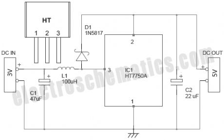
There are several ways to convert an AC voltage at a wall receptacle into the DC voltage required by a microcontroller. Traditionally, this has been done with a transformer and rectifier. However, in applications that involve providing a DC voltage to only the microcontroller and a few other low-current devices, transformer-based power supplies may not be cost effective.
Presented here is the simple circuit of one boost converter, which can output steady 5VDC supply from a 3VDC input. This circuit can be used to power your 5V microcontroller/similar circuits from two standard AA cells (1.5V x2).
(View)
View full Circuit Diagram | Comments | Reading(1163)
Battery Reverse Polarity Protection in LV Applications
Published:2013/8/20 23:03:00 Author:lynne | Keyword: Battery Reverse Polarity Protection in LV Applications
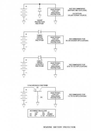
Accidentally connecting a battery reverse can be a real killer in electronic circuits. There are a number of ways to provide protection and all have the expected advantages and disadvantages. Any protection device connected in series with the battery reduces its voltage, and when the battery voltage is only in the order of 1.5 or 3V, every lost millivolt is significant. The highlight of this article is the use of a very low loss active or synchronous rectifier in low voltage applications. (View)
View full Circuit Diagram | Comments | Reading(1131)
MCP73826 500mA Lithium-Ion Battery Charger
Published:2013/8/20 22:59:00 Author:lynne | Keyword: MCP73826 500mA Lithium-Ion Battery Charger
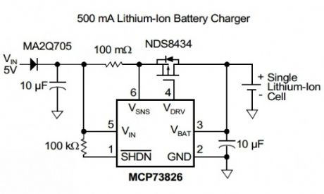
Here is presented a simple 500mA 4.1V or 4.2V Li-ion battery charger that is constructed with the MCP73826 linear charge management controller. There are two versions of this controller MCP73826-4.1 that is preset to a regulation voltage of 4.1V and MCP73826-4.2 with a preset of 4.2V.The IC operates with input voltage between 4.5V to 5.5V. Typical applications are:
single cell Lithium-Ion battery chargers
personal data assistants
cellular telephones
hand held instruments
cradle chargers
digital cameras
(View)
View full Circuit Diagram | Comments | Reading(1241)
ADP1649 1A LED Flash Driver
Published:2013/8/20 3:39:00 Author:lynne | Keyword: ADP1649 1A LED Flash Driver
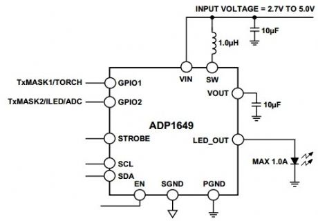
The ADP1649 is a very compact, highly efficient, single white LED flash driver for high resolution camera phones that improves picture and video quality in low light environments. The LED driver maximizes efficiency over the entire battery voltage range to maximize the input power-to-LED power conversion and to minimize battery current draw during flash events.ADP1649 applications
camera enabled cellular phones and smart phones
digital still cameras, camcorders, and PDAs
(View)
View full Circuit Diagram | Comments | Reading(969)
3A 6V/12V Solar Charge Control
Published:2013/8/20 3:12:00 Author:lynne | Keyword: 3A 6V/12V Solar Charge Control

This solar charge control combines multiple features into a single design: 3A current rating, low dropout voltage (LDO), range of voltage adjustment (accommodates 6 & 12V lead-acid batteries), reverse polarity protection, low parts cost ($5.90) and low parts count (14 components). High performance is attributed to the application of the common LM358 op amp and TL431 adjustable shunt voltage regulator.
Specifications
Max solar panel rating (12V): 43W (open circuit solar panel voltage = 18 to 20V)
Max solar panel rating (6V): 22W (open circuit solar panel voltage = 9 to 10V)
Maximum input voltage: 36V
Output voltage range: 4.5 to 15V (continuously adjustable)
Max power dissipation: 17W (includes power dissipation of D3)
Typical dropout voltage: 0.7V @ 3A (less @ lower currents)
Maximum current: 3A (current limiting provided by solar panel characteristics)
Voltage regulation: 5mV (voltage change no load to full load)
Battery discharge: 100µA (most commercially units discharge at typically 5mA)
Reverse battery protection: Control shuts down if battery is inadvertently connected reverse
(View)
View full Circuit Diagram | Comments | Reading(2244)
Troubleshooting Automotive Ignition Systems
Published:2013/8/19 0:55:00 Author:lynne | Keyword: Troubleshooting Automotive Ignition Systems

Automobile ignition systems have never been more reliable, but when not, how does one troubleshoot? and is it really an ignition issue? This simple test setup costs only about $1 and may easily be taken for a road test to help isolate mind-blowing intermittent problems. It consists of 2 LEDs and a meter. The standard means of troubleshooting is for a mechanic to change boxes and pass the cost onto the owner even if it does not solve the problem—and some systems have multiple boxes—and it might not even be a box issue. This method will help isolate the problem before making large expenditures.
When my car (86 Dodge Aries) developed intermittent problems, I took it to my mechanic. It ran perfectly while he checked it out. His response: “If it ain’t broke, I can’t fix it.” So I kept driving it until it stalled in pouring rain. I then pulled the wire from the coil to the distributor and checked for spark and it was DEAD. While that was useful information, it did not come close to isolating the problem. Eventually, it restarted after healing itself for another week.
(View)
View full Circuit Diagram | Comments | Reading(1112)
Read the State of a Button with Arduino – Tutorial #3
Published:2013/8/14 21:13:00 Author:lynne | Keyword: Read the State of a Button with Arduino , Tutorial #3
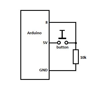
On the first line we set a variable pinButton with an integer value of 8 (the pin number on Arduino Board where we connect the button or switch). Then in the void() function we set the pin 8 as INPUT and initialize the serial port.
In the loop() we declare variable stateButton with the value obtained using the digitalRead() function that reads the state of pin 8. Then it displays its state in the Serial Monitor window as 0 or 1. There is also the delay() that ensures that we can actually read the value. A problem with the delay might be that if you press the button exactly when the delay happens (20ms in our case) then it will display the action in the windows, that why is better to use a lower value or else you might lose some clicks.
(View)
View full Circuit Diagram | Comments | Reading(1041)
Battery Capacity, Discharge and Load Testing
Published:2013/8/13 21:24:00 Author:lynne | Keyword: Battery Capacity, Discharge and Load Testing
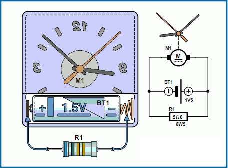
This project is cool because it features the re-use of found objects in electronics; things you might have laying around the garage, or at a yard sale, and thrift stores often have bins of this type of simple gear. It also is an easy tool for learning about battery discharge curves, loads, resistance, and testing capacity of different batteries.This is a simple and inexpensive battery testing setup, best for comparing different batteries capacities, or load testing to check the state of charge. If you calculate the current in this circuit and use the clock to measure the time it takes to discharge the battery you can get a good measure of the capacity of the battery.
This type of device is good for testing different brands or types of batteries, to compare them, or to determine which best needs your needs. You can figure out the cost per mah, and take DMM readings to get a discharge voltage curve to see how the cells hold or lose voltage under load.
This type of information is great for learning about characteristics of batteries in general, and how different chemistries of batteries act under load, which will be invaluable for deciding the size, type and chemistry for your future projects.
(View)
View full Circuit Diagram | Comments | Reading(1799)
| Pages:16/471 1234567891011121314151617181920Under 20 |
Circuit Categories
power supply circuit
Amplifier Circuit
Basic Circuit
LED and Light Circuit
Sensor Circuit
Signal Processing
Electrical Equipment Circuit
Control Circuit
Remote Control Circuit
A/D-D/A Converter Circuit
Audio Circuit
Measuring and Test Circuit
Communication Circuit
Computer-Related Circuit
555 Circuit
Automotive Circuit
Repairing Circuit