
Alarm Control
Index 5
Goods anti-theft annunciator circuit diagram ( transceiver module composed of RCMlA/RCMlB)
Published:2011/10/19 22:18:00 Author:Rebekka | Keyword: Goods anti-theft annunciator
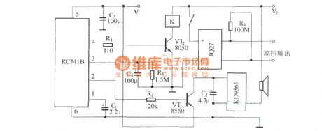
Emitter is composed of RCM1A and battery. Receiver is composed of receiver module RCM1B with double-delay function, high-voltage generator and the alarm circuit. (View)
View full Circuit Diagram | Comments | Reading(2151)
Eight-way wireless burglar alarm system circuit diagram
Published:2011/10/17 21:17:00 Author:Rebekka | Keyword: Eight-way wireless burglar alarm system

(a) shows the alarm monitoring and emission extension, KD9562 forms the alarm monitoring station launchesby 8 trigger terminals. The security monitoring circuit is composed of pyroelectric infrared detector module HL911L. When the situation occurs. HL911L's pin ① outputs high level. Then you can turnon the electronic switch to connect the internal circuit of TWH8778. TWH8778's pin ③ outputs high level, then the relay K is pulled in. Contaction switch KSwill makeemission component FDD5 work. (B) shows the host alarm receivingcircuit. When JDD5 gets the alarm signal sent by alarm extension. It will be demodulated. When JDD5 receives the alarm signal sent by the police station. The signal output by the output terminal is audio signal. It will make alarm sound through speaker. (View)
View full Circuit Diagram | Comments | Reading(1816)
Infrared alarm switch circuit diagram
Published:2011/9/26 22:15:00 Author:Rebekka | Keyword: Infrared alarm switch
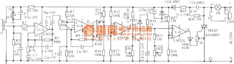
The figure shows the infrared alarm switch circuit. It uses the most popular domestic and international human pyroelectric PIR sensor as the signal detector. It has a high sensitivity, the detection range is up to 10m or more, the depression angles is up to 86 degrees, horizontal viewing angle is up to 120o. It is only sensitive to the specific wavelength infrared light that released by human body, so it has a minimal malfunction. When someone walks in the detection region in 0.3Hz ~ 3Hz frequency. It can give birth to weak signal sense. It is amplified by the UA, UB two-stage and outputs strong signal of 0.5V ~ 5.5V from the U-B7 feet. VD1, VD2, R10 ~ R13 and UC form the threshold comparator. The signal voltage induced by PIR can be positive or negative, so the U-B7 pin outputs voltage can be positive or negative (in terms of center voltage 3V). When the voltage on C8 is less than 13 feet (1V), the pin 14 has no output. Thyristor turns off, the lights automatically turn off. People sleep at night or when there is no one at home, you can turn off the switch S. If there is a thief sneaked into the detection region, the lights will be accompanied by ringing. It can scare away the thief, played the role of security. (View)
View full Circuit Diagram | Comments | Reading(3190)
Bell alarm circuit diagram
Published:2011/9/26 22:05:00 Author:Rebekka | Keyword: Bell alarm circuit
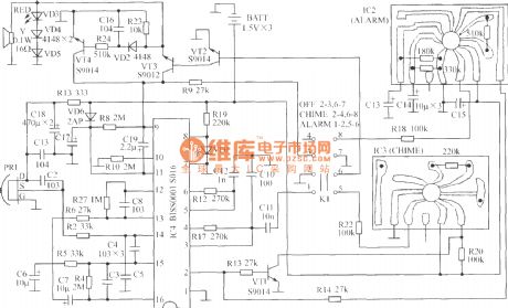
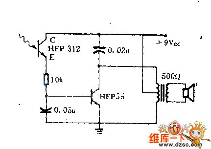
SNS-200P1 is the human body pyroelectric infrared alarm bell. SNS-200P1 uses three 5# batteries, portable design is ideal for alarm products. When the function switch isin the OFF position, the power off; In the CHIME position, it can be used for doorbell, when someone approaches, it will make ding-dong sound; In the ALARM position, it can be used as alarm, when some people close to the sound,thethe warning will be issued. The entire circuit is composed of body infrared detection sensor, the body infrared signal processing circuit, alarm audio circuits and audio amplifier circuit. (View)
View full Circuit Diagram | Comments | Reading(1924)
Temperature monitoring alarm equipment circuit
Published:2011/4/14 6:43:00 Author:may | Keyword: Temperature monitoring, alarm equipment
The temperature monitoring alarm equipment circuit introduced in this example has high , middle , low 3 gear temperature indication. It can send out alarm signal when the temperature is too high or too low. It can use in the occasion of big-arch shelter, greenhouse, etc which is needing temperature control.
This temperature monitoring alarm equipment consists of temperature monitoring/indication circuit and voice alarm circuit. The circuit is shown in the diagram.
Theoptions of components
R1~R4 chooses 1/4W metal-film resistor or carbon film resistor.
RP chooses compound film resistor or variable resistor.
VD1~VD3 all choose 1N4148 type silicon switching diode.
VL1~VL3 all choose Φ3mm LED
V chooses S8550 or 3CG8850 type silicon PNP transistor.
IC1 chooses ZH-3 type photometry application specific integrated circuit.
HA chooses DC electric magnetic buzzer with internal alarm voice source. (View)
View full Circuit Diagram | Comments | Reading(1017)
The alarm circuit diagram of optical intensity controlling
Published:2011/9/15 21:27:00 Author:Rebekka | Keyword: alarm circuit, optical intensity controlling
The circuit is available for hunters, fishermen go for a job at dawn. By flashlight or inside lights this circuit can betriggered. So it can be used as fire and burglar alarm circuit. Only when the lights die out, the alarm will stop. (View)
View full Circuit Diagram | Comments | Reading(1558)
Excess temperature alarm circuit diagram
Published:2011/9/15 22:32:00 Author:Rebekka | Keyword: Excess temperature alarm
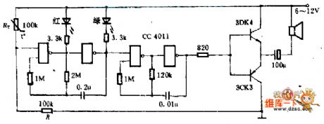
This circuitis composed ofa CMOS gate CC4011. It uses the ordinary thermistor for temperature measurement and it can emit sound, light and alarm. The two doors around the left side form the 2HZ controllable oscillator, and thetwo doors on the right formthe 400HZ controlled oscillator. When the temperature is normal, the partial-pressureof thermistor resistor RT and resistor R is lower than threshold voltage of NAND gate, two oscillators do not work. Once it is over temperature, RT is small enough, the first class NAND gate opens, the oscillator works, and the red and green light-emitting diodes alternating work, thenlthe oudspeaker emitssound. To save the transistor,it requires two tubes with the β> 150. (View)
View full Circuit Diagram | Comments | Reading(1295)
Low current anti-theft alarm circuit diagram
Published:2011/9/15 22:35:00 Author:Rebekka | Keyword: Low current anti-theft alarm
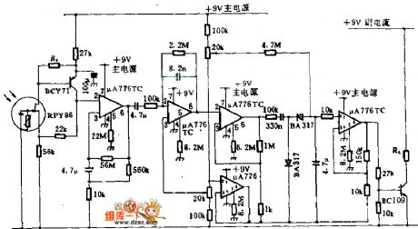
Detector RPY86 is produced by Mullard, and it only makes responses to the wavelength which isgreater than 6μm. It has not any response to thebackground light caused by sunlight and the sun. In order to gather infrared light onto the detector, it uses cheap mirror instead of Lens. μA776 is a programmable operational amplifier, and its bias current is only 300μA, which can be recharged by a small battery. Ra should be selected carefully, and the first operational amplifier's input voltage is 2 ~ 6V. Only when the thieves walk around the monitored area, the changes caused by the incident light will makethis circuit pull the alarm relay RL. (View)
View full Circuit Diagram | Comments | Reading(1617)
Missing pulse alarm circuit diagram
Published:2011/9/15 1:56:00 Author:Rebekka | Keyword: Missing pulse alarm
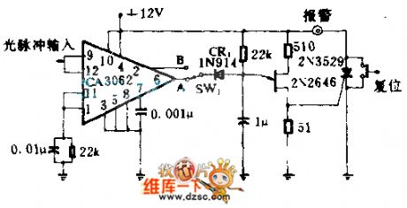
The circuit is used to detect the missing optical pulse or shortage of goods on the conveyor belt. CA3062 combination of detectors and amplifier can detect optical pulse which is synchronous with 60HZ power frequency . When switch SW1 is at A, every pulse has a interval of 16.7ms. It makes 2N2646 unijunction transistor reset at 20ms timing network. It avoids unijunction transistor triggering and triggers controlled rectifier. The alarm will be connected. When the SW1 at B, the circuit stops the detection of steady-state beam. It only alarmsat uninterrupted time.
(View)
View full Circuit Diagram | Comments | Reading(1497)
Water tank water level alarm circuit diagram
Published:2011/9/15 2:04:00 Author:Rebekka | Keyword: Water tank water level alarm
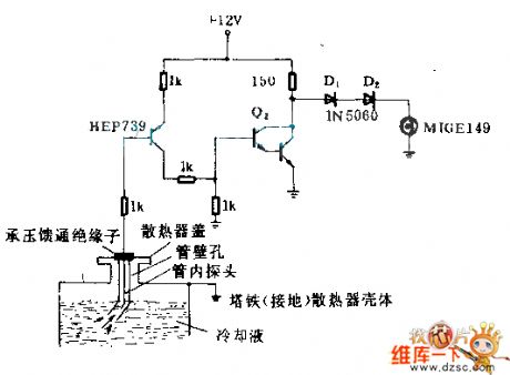
The insulator is stalledinto the lid of water tank. The insulator should suffer 0.717X10⁻⁴kg/m2 pressure from water tank. Metal probe passing the insulator is put into the liquid of water tank in the high temperature tube. There is small holes near to the one end of water tank lid. It can make the liquid rise in the tube and reach the probe. When the water level falls lower than the probe, the collector potancial of clad pipe Q2 rises and turns on the diode. The alarm M1 light will be lit. (View)
View full Circuit Diagram | Comments | Reading(2252)
Earthquake sound and light alarm circuit
Published:2011/9/14 21:06:00 Author:Rebekka | Keyword: Earthquake , sound and light , alarm

The circuit is composed of two integrated circuit chips as the core, and it has few external components, but experiments show the favorable results. It's the circuit is shown as the chart. 555 and R2, C1 form a monostable trigger, usually due to the small copper hammer is floating isolated, the pin 2 of 555 is connected to high potential Vnn by R1, thus making 555 be in a reset state, that is, pin 3 outputs low, then the backward stage does not work without electricity. HFC5212 is the high level trigger, and the quiescent current is very small, the working output current I0 is about 1mA, which can directly drive medium, low power tube.
(View)
View full Circuit Diagram | Comments | Reading(738)
The power failure alarm circuit
Published:2011/9/18 20:56:00 Author:Ecco | Keyword: Power failure , alarm circuit
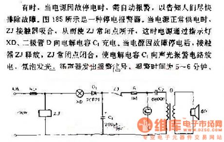
Sometimes, when the power is black out for some reasons, it needs to alarm automatically to inform people overcoming the breakdown as soon as possible. Figure 185 shows a power failure alarm. When power supply works normally, ZJ contactors pull in, so that the ZJ normal closed contact cuts off, then power is charged by the electrolytic capacitor C1 between the lights XD and diode D. When the power is black out for some reasons, ZJ contactors release, so that electrolytic capacitor C1 discharges to the sound and light alarm circuit, neon light bulbs turn on, speakers emit alarm signals, the alarm time is 5 to 6 minutes.
(View)
View full Circuit Diagram | Comments | Reading(998)
A humidity/frequency-audio decoding humidity detection, automatic exhaust ventilation croak sound circuit
Published:2011/8/26 2:05:00 Author:Jessie | Keyword: humidity/frequency, audio decoding humidity detection, automatic exhaust ventilation
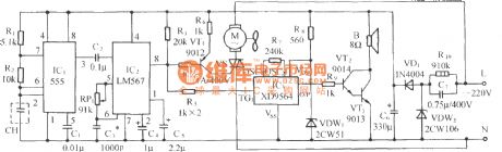
The circuit is shown as the chart, it is composedof wet sensors, time-based oscillator, audio decoder, SCR control exhaust fan circuit, croak sound circuit and AC step-down rectifier circuit, etc. Only when environment humidity reaches a set humidity value, audio decoderwill output signal of control fan start toundertake ventilated dehumidification, it also emits several croak sound to remind consumer's attention.
(View)
View full Circuit Diagram | Comments | Reading(1347)
Liquid surface safety alarm circuit with thermistors
Published:2011/8/26 2:10:00 Author:Jessie | Keyword: safety alarm, thermistors
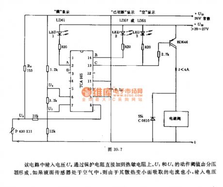
This circuit inputs voltage U8 is added to thermistorsthrough protection resistor . U7 and U6's action thresholdsare formedby bleeder. If liquid surface sensor isin air, its cooling decrescent surface absorbs little, input voltage U8 increses, but it is lower than threshold of U6. So integrated circuit output terminal C is connected, send out empty signal. At the same time, it flows thorugh the Dalindun transistor BD646 which makes the filling valve open. When thermistors liquid surface sensor dipped into the liquid, drain current increases, Rv's voltage drop increases, U8's voltage ris educed to U7's threshold, output A connects lamp L1, and it will show box full signal. When sensor isin short circuit, it will produce above-mentioned switch positions. But when sensor is disconnected, input voltage U8 increases to power voltage, higher than threshold. (View)
View full Circuit Diagram | Comments | Reading(1234)
Combustible gas alarm circuit diagram
Published:2011/8/17 21:14:00 Author:Jessie | Keyword: Combustible gas, alarm
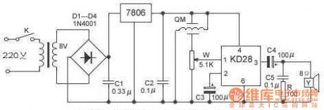
We usethe KD28 gas sensor probeand several componentstomake a combustible gas alarm device. When the combudstible gas of surrounding environment exceed a certain concentration, it can remind peopleto takemeasures.
Debugging: adjusting W (1 minute later) can make circuit not alarm, and thenwe access gas lighters (butane) to gas-sensitive element alarm untilitreturns normal work after gas left. This device's features are less component, commissioning simple. Itcan be usedin the detection of flammable gas such as gas, liquefied petroleum gas, natural gas and smoke etc.
(View)
View full Circuit Diagram | Comments | Reading(877)
Agricultural submersible pump anti-theft alarm
Published:2011/8/9 0:05:00 Author:Felicity | Keyword: anti-theft alarm, agricultural submersible pump
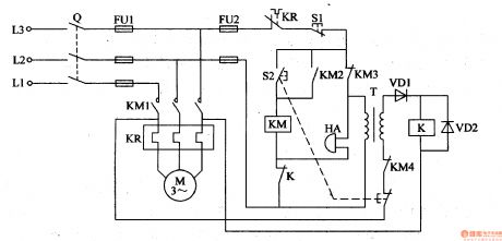
When the switch Q turns and the pump havn’t been started,the power transformer T is on.And the induced current produced by the secondary winding goes through the normally open contact of the AC contactor KM, the start-up button,and the stator winding of motor m to form a circuit. And then relay K switches on ,and the normally open contact releases to cut off the power circuit of coil KM and alarm HA. When the line is cut because of the pump being stolen or somehow,the power circuit of relay K will be cut off and its normally close contact closes and HA send alarm. (View)
View full Circuit Diagram | Comments | Reading(3459)
Frost alarm circuit diagram 2
Published:2011/8/11 1:22:00 Author:Ecco | Keyword: Frost alarm
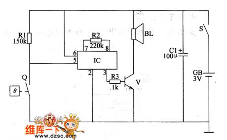
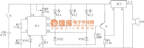
The frost alarm circuit is composed of the power supply circuit, control circuit and temperature detection alarm circuit, and it is shown in Figure 1. Power supply circuit consists of battery CB, power switch s and electric hot thermometer Q. The alarm circuit consists of the sound integrated circuit IC, resistors R2, R3, transistor V and the speaker BL. RI ~ R3 use the 1/4W metal film resistors or carbon film resistors. C selects the electrolytic capacitor with voltage in 6.3V. V uses the 59013 or CW9561-type audio integrated circuit. BL uses the 0.25W, 8Ω electric loudspeaker.
(View)
View full Circuit Diagram | Comments | Reading(1364)
Pressure tank air pressure abnormality alarm circuit diagram
Published:2011/8/11 0:58:00 Author:Ecco | Keyword: Pressure tank , air pressure , abnormality alarm

The pressure tank air pressure abnormality detection alarm circuit is composed of the pressure control circuit, LED indication circuit and voice alarm circuit, and it is shown as the chart. The air pressure measurement and control circuit is composed of the power switch S, battery CB, electric contact pressure gauge Q. LED indicator circuit is composed of the green LED VL1, red light-emitting diode VL2 and resistors R1, R2. R1 ~ R3 select the t/4W metal film resistors or a carbon film resistors. C1 select the electrolytic capacitor with voltage in 16V: C2 uses the high-frequency ceramic capacitor. VD1 and VD2 use 1N4001 or 1N4007 type silicon rectifier diodes.
(View)
View full Circuit Diagram | Comments | Reading(2073)
Single-button Ten-grade Timing Alarming Switch Circuit Diagram
Published:2011/8/9 17:56:00 Author:Vicky | Keyword: Single-button, Ten-grade, Timing Alarming Switch
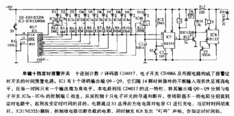
The time presetting circuit of the timing alarming switch is composed of decimal counter/decoder CD4017, electronic switch CD4066 and the peripheral circuits.IC1 has ten decoding output ends,Q0~Q9. They present high level in turn with the continuous input of 14 pin clock pulse. This circuit takes use of the feature of CD4017, and connects each of the output ends Q0~Q9 with the control end C of electronic switches IC2a~IC4b respectively so as to control these ten the electronic switches and enable the resistances of different resistance value to be connected with the timing circuit, which can reach the goal of changing the timing time. The power supply charges the capacitance C1 via the charging resistor chosen by S1. When the time is over, IC5 (NE555) spins, the control relay cuts off the laden power supply, and meanwhile the trigger IC6 gives out rub-a-dub sound to tell it’s time up. (View)
View full Circuit Diagram | Comments | Reading(1114)
Monolithic Alarming Timer Circuit Diagram
Published:2011/8/9 17:57:00 Author:Vicky | Keyword: Monolithic, Alarming Timer

Monolithic Alarming Timer
IC1 is a 14 decimals counter/frequency divider and oscillator, which can work in a relatively wider range of frequency. When S1 closes, R4 and C2 can generate positive pulse when are turned on, and reset the counter. Then it begins counting. When it comes to 14 decimals, the 3 pin represents high level, and T1 drives the piezoelectric buzzer to produce sound. The time delay function can be adjusted by P1. Then relationship between time delay and parameters of components is shown as follows:
1 ~ 30 min: C1= 200mF; P1= 500KΩ;
1 ~ 60 min: C1= 470mF; P1= 500KΩ;
1 ~ 200 min: C1= 470mF; P1= 1MΩ. (View)
View full Circuit Diagram | Comments | Reading(912)
| Pages:5/18 123456789101112131415161718 |
Circuit Categories
power supply circuit
Amplifier Circuit
Basic Circuit
LED and Light Circuit
Sensor Circuit
Signal Processing
Electrical Equipment Circuit
Control Circuit
Remote Control Circuit
A/D-D/A Converter Circuit
Audio Circuit
Measuring and Test Circuit
Communication Circuit
Computer-Related Circuit
555 Circuit
Automotive Circuit
Repairing Circuit