
Alarm Control
Index 2
Timer alarm circuit using NE555
Published:2012/12/12 2:52:00 Author:Ecco | Keyword: Timer alarm
Timer alarm circuit using NE555 is shown as the figure.
(View)
View full Circuit Diagram | Comments | Reading(1168)
Alarm circuit diagram using pyroelectric sensor
Published:2012/12/11 0:04:00 Author:Ecco | Keyword: Alarm , pyroelectric sensor

The circuit is composed of amplifier, comparator and an output control part. According to Faraday's law, person's body temperature is about 37 ℃, radiation infrared wavelength is about 10μm, the pyroelectric sensor selects P7178 with 7 ~ 20μm sensitive wavelength range. A1 and A2 are selected low noise, low loss CMOS op amp μPC358, and it is connected to band-pass filter composed of RC to prevent the entry of the noise and error signal, extracting only a signal when the human body moves. A3 and A4 constitute a comparator.
(View)
View full Circuit Diagram | Comments | Reading(1605)
High sensitivity anti-theft alarm circuit with high loudness
Published:2012/12/2 21:28:00 Author:Ecco | Keyword: High sensitivity, anti-theft alarm, high loudness

The SCR, R2 and L form a triggered power switch with controllable disconnection, L is an anti-theft wire. Transistor VT and IC1 form approximately 2min monostable delay trigger circuit. IC2 is the language alarm circuit which can emit the sound of catch thief, please . Usually when K is closed, if there is no thief, the alarm burglar lines will make SCR control gate trigger current be short, SCR is off, the circuit does not work, and it is in the probation status. If thied jumps over the wall of park, the wire L is pulled and disconnected, SCR control pole gets triggered current by R2, then it is be turned on to provide the power for working circuit.
(View)
View full Circuit Diagram | Comments | Reading(1276)
The roadblocks flashing alarm circuit ( 4 )
Published:2012/11/5 20:48:00 Author:Ecco | Keyword: roadblocks flashing, alarm

Road blocks flashing warning light using battery is shown in the figure, and it can be used local road facilities without AC power for roadblocks alarm. NE555, RP1 , RP2 , C1 , RL and RL form a a light -controlled self-excited multivibrator. Due to light exposure in daytime, it is in low resistance, NE555 forces reset terminal ④ feet level to be less than 0.4V, and the NE555 is mandatory reset, output end ③ feet is constant low, then VT1 and VT2 are cutoff, warning lights E does not shine. Due to RL has no light exposure in nighttime, it shows a high resistance, then it is divided by RP2 to make ④ feet level increase, when it is greater than 0.4V, you can lift the blockade on the circuit, the circuit is start-up.
(View)
View full Circuit Diagram | Comments | Reading(1202)
Open circuit, short circuit anti-theft alarm
Published:2012/10/31 21:00:00 Author:Ecco | Keyword: Open circuit , short circuit , anti-theft alarm

It uses AC driver to make higher light power output by the light emitting diode, the driver circuit is shown in Figure. The two LEDs are connected reversely in parallel, so that the power's positive and negative half-cycle can be dispalyed by a light-emitting diode.
(View)
View full Circuit Diagram | Comments | Reading(1605)
Gas, gas detection alarm circuit using CH217 monolithic gas, gas detection alarm integrated circuit
Published:2012/10/30 21:24:00 Author:Ecco | Keyword: Gas, gas detection , alarm , monolithic gas, alarm integrated circuit
R1 in Figure is agas sensing probe, and its resistance reduces with a linear relationshipto gas concentration increasing, andRP3 is used to adjust the output ofamplifier, R6, R7 are used to draw forecasting and risk baseline signal voltages.
(View)
View full Circuit Diagram | Comments | Reading(1126)
LOW acoustic-optical siren circuit
Published:2012/10/28 21:02:00 Author:Ecco | Keyword: LOW , acoustic-optical siren
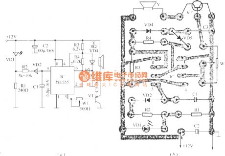
The circuit can generate high intensity warning sound, and it can be used as anti - theft siren. When power alarm system is connected, VD1 flashes and eimts light, R1 resistor outputs pulse square wave which is converted into triangle wave after passing R2, VD2 and C1 network, IC is a 555 time-base circuit to form a voltage-controlled oscillator. R3, R4 and C3 are timing elements. Under the control of the triangular wave, the output variable tone signals is amplified by VT to promote speakers, and its output power closes to l0W. Adjusting R1 can change the amplitude of the triangle wave on C1, and adjusting W1 can change the volume. Figure (b) is a printed circuit board installation diagram.
(View)
View full Circuit Diagram | Comments | Reading(1264)
Alarm circuit diagram using op amp
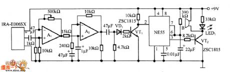
Published:2012/10/25 21:29:00 Author:Ecco | Keyword: Alarm , op amp

A1 and A2 form the two-stage amplifier which can amplifer output signal of pyroelectric sensor IRA-E006SX to a desired level. A3 is a comparator, and RP adds reference voltage to the inverting input terminal of A3, whe A2 output level is higher than the reference voltage, A3 outputs a high level to make VT1 conduction, relay κ action to drive the alarm.
(View)
View full Circuit Diagram | Comments | Reading(1339)
The alarm circuit diagram using DS-505 pyroelectric sensor
Published:2012/10/25 21:26:00 Author:Ecco | Keyword: alarm , pyroelectric sensor
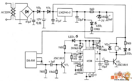
In the circuit, DS-505 receives the infrared radiation from human body and turned it into a voltage signal, then it is amplified by VT1 and added pin 5 of 4538 ( B - side) to start timer, then the pin 6 ( Q side) outputs high level, and VT2 gets conduction to drive relay K action its contacts are connected to the alarm device alarm. In the circuit, the timing time is determined by the time constant of RP1 and C1, R1 and C2 are used to prevent the erroneous operation of the timer when the power is turned on , LED1, LED2 and LED3 respectively show the power supply, sensor output and the operation of the relay.
(View)
View full Circuit Diagram | Comments | Reading(1980)
Triac gas - smoke alarm circuit schematic
Published:2012/10/24 21:29:00 Author:Ecco | Keyword: Triac , gas - smoke alarm

In the event of combustible gas, the conductance of TGS308 gas sensor increases, and the voltage is removed through the potentiometer RP1 slide point, and its value is increased from normal 3V rms to 20V. This elevated voltage is added to transistor VT1 through diode and 4.7kΩ resistor, so that VT1 gets conduction, then Triacs 2N6070A gets conduction. Thus, the full-wave AC voltage drives H to produce up to 90dB alarm sound. H is Detal6003168 24V AC alarm. When gas disappears from the sensor, the circuit is restored to the original state, so the alarm automatically stops.
(View)
View full Circuit Diagram | Comments | Reading(1749)
Gas smoke alarm circuit
Published:2012/10/21 20:41:00 Author:Ecco | Keyword: Gas smoke alarm

TGS308 gas sensor conductance ( Figure 5.18 ) increases in the event of combustible gas, and the voltage is got by the potentiometer RP1 slide point, and its value is increased from normal 3V rms to 20V, this elevated voltage is added to transistor VT1 by diode and 4.7kΩ resistor, so that it gets conduction, VT1 conduction makes Triacs 2N6070A get conduction. Thus, full-wave AC voltage can drive E to produce up to 90dB alarm sound. H is Deltal6003168 type 24V AC alarm. When gas disappears from the sensor, the circuit is restored to the original state, so the alarm automatically stops.
(View)
View full Circuit Diagram | Comments | Reading(1019)
The control alarm circuit with SGZ07 sound and light alarm integrated circuit
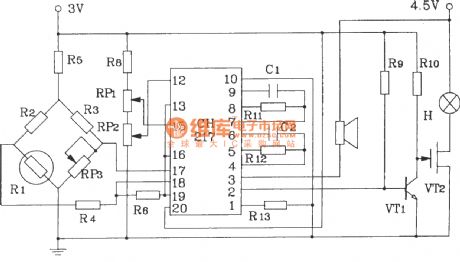
Published:2012/10/10 22:04:00 Author:Ecco | Keyword: control alarm , sound and light, alarm, integrated circuit
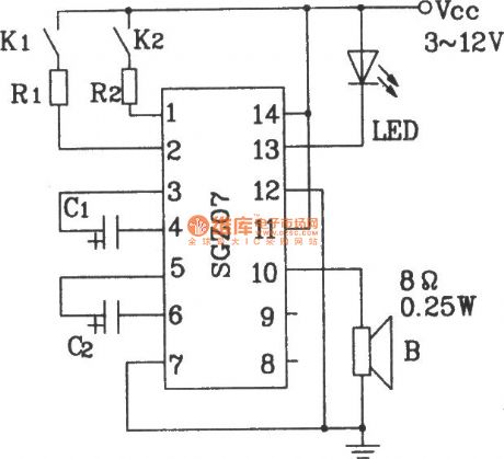
In the figure, the on-off of K1 the K2 allow the circuit to work in dual-band sound, light alarm circuit. If the R1, R2 of circuit are replaced by the corresponding thermistors ( measured value), it can realize the temperature control alarm circuit.
(View)
View full Circuit Diagram | Comments | Reading(1103)
ZKB8711 self-control alarm integrated circuit for thermostat automatic control alarm circuit
Published:2012/10/10 21:36:00 Author:Ecco | Keyword: self-control, alarm , integrated circuit, thermostat , automatic control , alarm
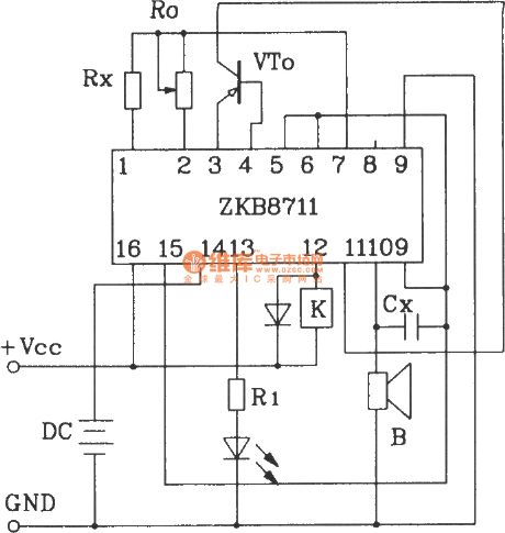
ZKB8711 can be used for temperature control, light control, rain control humidity control and hazardous gas detection alarm, the circuits with ZKB8711 have less external components, and they are easy to make.
(View)
View full Circuit Diagram | Comments | Reading(1627)
Bike Guard Alarm Circuit
Published:2012/9/27 21:25:00 Author:muriel | Keyword: Bike Guard, Alarm Circuit
This Simple circuit can be used to Guard your bike from theft. It gives a loud alarm tone if somebody tries to start the bike. The alarm disables only when the hide switch S2 is opened. The circuit has little component count and can be easily fixed in the bike.Working of the circuit is simple. The alarm generator buzzer or Horn is activated by an SCR and its triggering is under the control of the transistor T1. In the Armed position, Switch S2 is closed and S1 (Key switch of the bike) is opened. In this state, T1 will not conduct and SCR and Buzzer remains idle in armed position. When somebody turns on the Key switch of the Bike using a duplicate key, Capacitor C1 charges through R1, D1 and R2. It will take a time delay of few minutes to attain full charge in C1. When C1 fully charges T1 conducts and triggers the SCR. Buzzer connected to the Anode of SCR gets electrical path and it sounds the alarm. LED also lights to indicate the theft. The time delay is added through C1 so that the alarm will sound only after the bike is started .This aborts the attempt of theft.
Bike Guard Alarm Circuit diagram
The unit should hide in a place like the Carrier Box. So that switch S2 can be protected. An additional bike horn can be connected in the place of the buzzer to get loud sound. Connection point from R1 should go to the key switch point that goes to the engine so that; the unit will be activated only if the key switch is closed. Time delay can be changed by changing the value of C1 or R2. Hide switch S2 should be kept closed for arming the bike only after removing the switch key. Power to the circuit is obtained from the 6/12 volt bike battery. High current type transistor T1 and SCR are used to handle the high power of bike battery.Use 1 watt resistors to handle high power.Note: This circuit is not sufficient if the tricky thief knows some electronics. (View)
View full Circuit Diagram | Comments | Reading(1343)
Anti-theft Car Alarm circuit
Published:2012/9/27 21:23:00 Author:muriel | Keyword: Anti-theft, Car Alarm
Here is a simple Anti theft car alarm device for your Car. It generates a loud alarm when there is an attempt of theft. When the intruder opens the door, the circuit senses the attempt of theft and after 2 minutes, the alarm will be activated. The time delay is provided to help the user to leave the car after arming with the deviceThe anti theft alarm circuit taps power supply from the car battery. Switch S1 is the on/ off switch of the alarm circuit. When the circuit is activated through S1, the flashing LED blinks indicating that the car is armed. But the alarm generator works only if the Dome lamp of the car is switched on through the door switch. This switch turns on the dome lamp, if any one of the door is opened. The user can put S1 in the on position before leaving the car.
There will be a delay of 2 minutes so that the alarm will not be generated. When the intruder opens the door, Diode D1 forward biases and capacitor C1 charges through R1. It takes around 1 minute to charge C1. When C1 fully charges, the 12 volt Zener conducts to trigger the NPN transistor T1.Zener diode switch is provided to avoid false triggering and T1 conducts only when C1 charges fully. When T1 conducts C2 charges and the voltage in C2 triggers the gate of SCR. The Horn connected to the Anode of the SCR sounds indicating the theft. The horn can be either a spare car horn or a Hooter that gives loud alarm.
Anti-theft Car Alarm Circuit diagram
Note: Before leaving the car, switch on S1 and after entering the car switch off S1. Hide S1 in a place that cannot be detected. (View)
View full Circuit Diagram | Comments | Reading(1253)
Flame Failure Monitor
Published:2012/9/26 21:16:00 Author:muriel | Keyword: Flame Failure, Monitor


A minimum amount of hardware is needed to build a simple flame or fire failure monitor that enables you to monitor the status of the flame in a chamber/furnace. Owing to its integrated alarm generator, the interface can be easily adapted for use with a wide range of light/heat sensors. Here a readily available photo transistor 2N5777 (T1) works as the flame sensor. The 5V regulated dc supply for this circuit can be derived from a 12 V mains adaptor or a 9V rechargeable battery. In the presence of the flame, T1 conducts (resistance low) and most of the base current of relay driver transistor T2 find an alternative easy path via T1. As a result T2 remains cutoff. If flame is absent, T1 behaves almost an open circuit, and the current through P1 and R1 flows into the transistor’s (T2) base.
Next, the 5V reed relay is energised and 5V positive supply is extended to the alarm generator circuit built around the siren generator UM3561(IC1). Output signals from IC1 is amplified by transistor T2 to drive a standard 64 Ohm 1W mylar speaker.
For optimum perfomance, enclose phototransistor (T1) in a suitable long tube and add an optical assembly (see fig.2). The adjustment of sensitivity set preset pot P1 is also very critical.
Flame (fire) Monitor Circuit Diagram
(View)
View full Circuit Diagram | Comments | Reading(1236)
Cashbox or Locker Alarm
Published:2012/9/25 21:48:00 Author:muriel | Keyword: Cashbox, Locker, Alarm circuit

The locker alarm circuit or cashbox watcher can be used to protect a cashbox/locker from unauthorised access. This tried and tested design forms a fool-proof,remotely operated alarm/electromagnetic relay driver that receives its control signal from a standard reed switch. The circuit works off a 12V dc power supply.After construction, enclose the whole circuit, including the power supply (preferably with a backup facility) in a tamper proof metallic box and keep it in a secure location. For optimum safety, use key lock type switches for power (S3) and reset(S2) control. Now open your cashbox/locker and fix a strong permanent magnet in its door and the reed switch(S1) in the door frame so that when door is closed, the magnet is very near to S1. Now connect the terminals of reed switch to the input of the main circuit using a strong two-core cable.Operation of the locker alarm circuit, built around CD4001(IC1) is straight forward. When switch S3 is turned to ON state,the 12V supply is extended to the whole circuit.Normally, when cashbox/locker is closed, the reed switch is also closed due to the presence of bar magnet and hence the the output (at pin 10) of IC1 (Quad 2-input NOR gate pack) is in logic low state.When the cashbox/locker is opened, reed switch also opened and the output state changes to logic high level to enable the bistable latch realised using next two NOR gates (Final NOR gate is not used here). As a result, driver transistor (T1) activates to drive the output load. A ready made 12V electronic hooter or a standard 12V electromagnetic relay can be used as the output load. Push-to-on type switch (S2) is the reset switch for the bistable circuit.
Locker Alarm Circuit Diagram/Schematic
(View)
View full Circuit Diagram | Comments | Reading(2392)
Cultural treasures anti-metal closing audible and visual alarm circuit
Published:2012/9/20 21:25:00 Author:Ecco | Keyword: Cultural treasures , anti-metal closing , audible and visual alarm
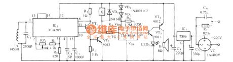
As shown in the figure, the circuit consists of electromagnetic inductive proximity switch, relay control circuit, whistle analog voice circuit and AC buck rectifier circuit. This circuit can be used for prevention of burglary in museum, artifacts or treasures Collection Room. When someone uses metal artifacts to open the cabinet, the circuit will automatically send alarm whistles and start relay control circuit to turn on the light or camera equipment.
(View)
View full Circuit Diagram | Comments | Reading(1721)
Shadow Alarm Circuit
Published:2012/9/21 2:33:00 Author:Ecco | Keyword: Shadow Alarm
This shadow alarm circuit can sense a moving shadow in a confined area. It can be used to protect things from theft. When somebody approaches the unit, it will give a loud alarm to abort the attempt of theft. The circuit uses the light sensing property of the Photo diode.The circuit uses the light sensing property of the PIN Photodiode. The p-n junction of the photo diode gives light current when it is forward biased. IC1 is designed as a voltage comparator. Its non inverting input is connected to a potential divider R1 and VR. By adjusting VR, input current to pin3 can be set to a reference level. The inverting input of IC1 is connected to a photo diode. IC CA3130 is a 15 MHz BiMOS Operational amplifier with MOSFET inputs and bipolar output. The inputs contain MOSFET transistors to provide very high input impedance and very low input current as low as 10pA. It has high speed of performance and suitable for low input current applications.
CA3130A and CA3130 are op amps that combine the advantage of both CMOS and bipolar transistors. Gate-protected P-Channel MOSFET (PMOS) transistors are used in the input circuit to provide very-high-input impedance, very-low-input current and exceptional speed performance. The use of PMOS transistors in the input stage results in common-mode input-voltage capability down to 0.5V below the negative-supply terminal, an important attribute in single-supply applications.
A CMOS transistor-pair, capable of swinging the output voltage to within 10mV of either supply-voltage terminal (at very high values of load impedance), is employed as the output circuit.
The CA3130 Series circuits operate at supply voltages ranging from 5V to 16V, They can be phase compensated with a single external capacitor, and have terminals for adjustment of offset voltage for application requiring offset-null capability. Terminal provisions are also made to permit strobing of the output stage. The CA3130A offers superior input characteristics over those of the CA3130.
Normally in the light ( as set by VR) Photodiode gives voltage to pin2 of IC1.Since this voltage is higher than the voltage set by VR at pin3 ,output of IC1 remains low keeping LED and buzzer off. When a person approaches the photodiode, the shadow causes a reduction in current through the photodiode so that voltage at pin2 decreases below that of pin3. Output of IC1 then goes high and Buzzer sounds.
NoteThe circuit triggers when the light intensity changes without a shadow. It is better to keep the unit in a place where constant light is available
Shadow Alarm Circuit diagram
?
68 Responses to “Shadow Alarm Circuit”
source: electroschematics.com (View)
View full Circuit Diagram | Comments | Reading(1158)
Water sensor alarm
Published:2012/9/20 20:52:00 Author:Ecco | Keyword: Water sensor, alarm

This small water sensor alarm circuit makes a loud warning sound when a humidity sensor detects a quantity of water. This circuit assembly is an application of low power comparator LM1801 made by National Semiconductor. The reference voltage for the integrated circuit is fixed with the help of R2.When pin 4 of the LM1801 voltage exceeds preset threshold, because the moisture sensor noticed a smaller or larger chip will command the active piezoelectric buzzer with a current of over 24 mA.
In the surveillance state, the water sensor alarm circuit has a current consumption of 10 microAmps so you can use a 9V battery for almost one year. We can connect many sensors simultaneously.
Water sensor alarm circuit diagram
?
3 Responses to “Water sensor alarm”
Source: electroschematics.com (View)
View full Circuit Diagram | Comments | Reading(3117)
| Pages:2/18 123456789101112131415161718 |
Circuit Categories
power supply circuit
Amplifier Circuit
Basic Circuit
LED and Light Circuit
Sensor Circuit
Signal Processing
Electrical Equipment Circuit
Control Circuit
Remote Control Circuit
A/D-D/A Converter Circuit
Audio Circuit
Measuring and Test Circuit
Communication Circuit
Computer-Related Circuit
555 Circuit
Automotive Circuit
Repairing Circuit