
Alarm Control
Index 9
HEADLIGHT_ALARM
Published:2009/7/6 3:48:00 Author:May
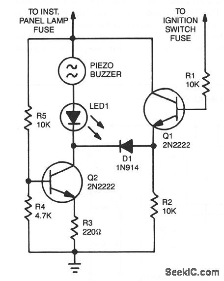
The base of Q1 is connected to the car's ignition circuit. One side of the piezoelectric buzzer is connected to the instrument-panel light fuse. When the headlights are off, no current reaches the buzzer, and therefore nothing happens. What happens when the headlights are on depends on the state of the ignition switch. When the ignition switch is on, transistors Q1 and Q2 are biased on, removing the buzzer and the LED from the circuit.When the ignition switch is turned off, but the headlight switch remains on; transistor Q1 is turned off, but transistor Q2 continues to be biased on. The result is that the voltage is sufficient to sound the buzzer loudly and light the LED. Turning off the headlight switch will end the commotion quickly. (View)
View full Circuit Diagram | Comments | Reading(0)
PRESET_FREQUENCY_ALARM
Published:2009/7/6 1:35:00 Author:May
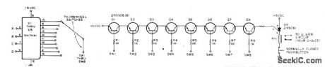
When selected frequency occurs in Nixie-driving counter, alarm circuit triggers and locks until reset manually. Requires one SN7441 Nixie decoder/driver, one decimal-type thumbwheel switch, and one 2N3905 transistor for each digit of display in counter. Four connections are made to each counter stage to get BCD inputs A, B, C, and D for 7441. Connections can be made to 7475 quad latch in typical counter. Circuits are for 8-digit display. When display reaches digit to which switch is set, switch output is grounded. When all switch outputs are grounded, all transistors are turned on and SOP fires to actuate alarm relay. If latching is unclesirable, use medium-power NPN transistor in place of SCR.-W. L. MacDowell, Frequency Detector for Your Counter, 73 Magazine, Oct.1976 p 50-51. (View)
View full Circuit Diagram | Comments | Reading(1041)
FIELD_DISTURBANCE_SENSOR_ALARM
Published:2009/7/5 23:12:00 Author:May

Circuit NotesThe changein ambient light triggers the alarm by changing resistance of LDR1 and LDR2, Q1=Radio Shack 276-2024 A1=Mallory SC628P Sonalert LDR1,LDR2=Cadmium sulfide photoce⒒,Radio Shack 276-116 (View)
View full Circuit Diagram | Comments | Reading(976)
PROXIMITY_ALARM
Published:2009/7/5 23:08:00 Author:May

Circuit Notes
Inverters U1a and U1b are connected in a simple RC oscillator circuit. The frequency is determined by the values of R1, C1, C2, and the intemal characteristics of the integrated circuit. As long as, the circuit is oscillating, a positive dc voltage is developed at the output of the voltage-coupler circuit: C3, D1, D2 and C4. The dc voltage is applied to the input of Ulc-the third inverter amplifier-keeping its output in a low state, which keeps Q1 turned off so that no sound is produced by BZ1. With C1 and C2 adjusted to the most sensitive point, the pickup plate will detect a hand 3 to 5-inches away and sound an alert.Set C1 and C2 to approximately one-half of their maximum value and apply power to the circuit. The circuit should oscillate and no sound should be heard. Using a non-metallic screwdriver, carefully adjust C1 and C2, one at a time, to a lower value until the circuit just ceases oscillation: Buzzer BZ1 should sound off. Back off either C1 or C2 just a smidgen until the oscillator starts up again-that is the most sensitive setting of the circuit. (View)
View full Circuit Diagram | Comments | Reading(0)
LOW_VOLTS_ALARM
Published:2009/7/5 22:50:00 Author:May

Circuit Notes
This inexpensive dc supply-voltage monitor sounds a warning when the voltage falls below a preset value. It is ideal for monitoring rechargeable batteries since it draws only a few microamperes when not sounding. The voltage at which the alarm sounds is determined by the zener diode. When the voltage falls below the zener voltage, the alarm sounds. The alarm tone is determined by the RC time constant of the 39 k resistor and 0.01 mf capacitor. (View)
View full Circuit Diagram | Comments | Reading(0)
MALFUNCTION_ALARM
Published:2009/7/5 22:42:00 Author:May
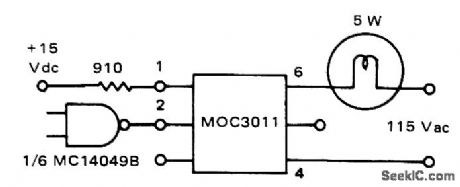
Motorola MOC3011 optoisolator serves as interface between CMOS logic of microprocessor and 5-W 115-VAC lamp.Input logic is connected to energize infrared LED of optoisolator by providing up to 50 mA.Once triggered, indicator lamp remains on until current drops below holding value of about 100 μA.-P. O'Neil, Applications of the MOC3011 Triac Driver, Motorola, Phoenix, AZ, 1978, AN-780,p2. (View)
View full Circuit Diagram | Comments | Reading(1145)
IONIZATION_ALARM
Published:2009/7/5 22:38:00 Author:May

Gates in Motorola MC14572 CMOS IC form two alarm oscillators, one energized in presence of smoke at ionization chamber and other for low battery.Standby currents of circuits are low enough to give at least 1 year of operation from 750-mAh battery. R6 is adjusted to give desired smoke detection sensitivity. Gates 1 and 2 form MVBR that drives horn at astable rate of 2.5 s on and 0.2 s off in presence of smoke. When battery is low, comparator Q4-D2-D3 trips (about 10.5 V) and energizes inverter 4 of low-battery astable MVBR. DC horn is then powered at astable rate of about 1 s every 23 s to give early warning of need to change battery.-A. Pshaenich, Solid State Gas/Smoke Detector Systems, Motorola, Phoenix, AZ, 1975, AN-735, p 7.
(View)
View full Circuit Diagram | Comments | Reading(1119)
IONIZATION_ALARM_USING_TRANSISTORS
Published:2009/7/5 22:21:00 Author:May

Use of continuous smoke alarm signal rather than beeping horn simplifies transistor circuits needed to trigger fire alarm and low-battery alarm. When high impedance of ionization chamber is lowered by smoke or gas, amplifier Q1-Q2-Q3 supplies 100-μA base current to Darlington Q4 for powering hom continuously as Iong as smoke content exceeds that set by threshold control R5. Low-battery circuit is tdpped at voltage range between 9.8 and 11.2 V, as determined by R13, to energize MVBR Q8-Q9 for driving horn 0.7 s, with 50-s OFF intervals.Battery is chosen to last at least t year while furnishing standby current of about 70μA.-A.Pshaenich, Solid State Gas/Smoke Detector Systems, Motorola, Phoenix, AZ, 1975, AN-735,p 8. (View)
View full Circuit Diagram | Comments | Reading(1417)
FAIL_SAFE_ALARM
Published:2009/7/5 21:28:00 Author:May
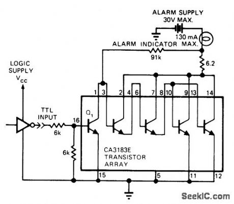
Circuit monitors status of microprocessor system and energizes lamp or other alarm indicator to indicate when CPU halts or power is lost. Input is TTL-compatible, and output can drive loads up to 130 mA at 30 V.-J. Elias, Alarm Driver Is Fail-Safe, EDN Magazine, May 20, 1975, p 76. (View)
View full Circuit Diagram | Comments | Reading(831)
ICE_FORMATION_ALARM
Published:2009/7/3 3:31:00 Author:May

The circuit warns car drivers when the air temperature close to the ground approaches 0℃, thereby indicating possible formation of ice on the road surface. Op amp A1 is wired as a voltage level sensor. Op amp A2 is wired as an astable multivibrator which, by means of current buffer Tr1, flashes a filament lamp at about 1 Hz. As air temperature falls, a point is reached when the voltage at pin 2 just rises above the volt-age at pin 1. The output of A1 is immediately driven into positive saturation, since it is operated open loop. This positive output voltage powers A2 through its V + connection on pin 9, starting the oscillator. The thermistor is a glass bead type with a resistance of about 20 MΩ at 20℃. VR1 is adjusted so that the lamp starts flashing when the air temperature is 1 to 2℃. (View)
View full Circuit Diagram | Comments | Reading(1640)
ROAD_ICE_ALARM
Published:2009/7/3 3:27:00 Author:May

The circuit uses a thermistor and three sections of a LM3900 quad op amp IC. When the temperature drops to 36°F the LED indicator flashes about once each second. The flashing rate increases as temperature drops to 32°F when the LED remains on. Amplifier I compares the thermistor's resistance to the resistance of the standard network connected to its noninverting input. Its output-fed to the noninverting input of op amp III-varies with temperature. Op amp II is a free-running multivibrator feeding a pulse signal of about 1 Hz to the inverting input of op amp III. This amplifier compares the outputs of op amps I and II and turns on the LED when the multi-vibrator's output level drops below op amp I. The monitor is calibrated by placing the thermistor in a mixture of crushed ice and water and adjusting the 20 kΩ pot so the LED stays on. (View)
View full Circuit Diagram | Comments | Reading(1123)
BURGLAR_ALARM_2
Published:2009/7/3 3:00:00 Author:May

This circuit cannot be shut off for 10 to 60 seconds-even if the trip condition is immediately removed.It draws no standby power from the battery and is self-resetting.
(View)
View full Circuit Diagram | Comments | Reading(680)
BURGLAR_ALARM
Published:2009/7/3 2:58:00 Author:May
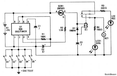
The heart of the circuit is a 555 oscillator/timer, U1, configured for monostable operation. The output of U1 at pin 3 is tied to the gate of SCR1. As long as S1-S5, which are connected to the trigger input of U1, are open, the circuit remains in the ready state, and does not trigger SCR1 into conduction. Because the relay is not energized, battery current is routed through the relay's normally-closed terminal and through current-limiting resistor R3 to LED2, causing it to light.However, when one of the switches (S1-S5) is closed, grounding U1 pin2, the output of U1 at pin 3 increases, activating SCR1. That energizes the relay, pulling the wiper of K1 to the normally-open termi-nal, causing LED1 to light and BZ1 to sound.The duration of the output is determined by the RC time-constant circuit, formed by R1 and C1.Resistor R2 regulates the output of U1 to a safe value for the gate of SCR1. Switches S1-S5 are to doors, windows, etc. A switch can be connected in series with B1 to activate and deactivate the alarm circuit when it's not needed. (View)
View full Circuit Diagram | Comments | Reading(0)
LOW_VOLTS_ALARM
Published:2009/7/3 2:55:00 Author:May

Circuit Notes
This inexpensive dc supply-voltage monitor sounds a warning when the voltage falls below a preset value. It is ideal for monitoring rechargeable batteries since it draws only a few microamperes when not sounding. The voltage at which the alarm sounds is determined by the zener diode. When the voltage falls below the zener voltage, the alarm sounds. The alarm tone is determined by the RC time constant of the 39 k resistor and 0.01 mf capacitor. (View)
View full Circuit Diagram | Comments | Reading(1027)
SINGLE_IC_AUTO_ALARM
Published:2009/7/3 2:36:00 Author:May


See (a) for the timing information for the alarm circuit in (b). When leaving your vehicle, flip the arming switch and close the door to arm the device. Subsequent opening of an entrance triggers both timers.After the expiration of the entry delay timer, the alarm sounds for a time determined by the second timer.The value of R should be less than 1 KΩ. If you use an incandescent lamp instead of a resistor, you get an extra function-an open-entrance indicator. By keeping the resistance low, you avoid false tripping should water collect under the hood. If your door switch connects the courtesy light to 12 V rather than ground, use a single transistor as an inverter at the input. (View)
View full Circuit Diagram | Comments | Reading(846)
SEMICONDUCTOR_FAIL-SAFE_ALARM
Published:2009/7/3 2:32:00 Author:May

False alarms produced by semiconductor failure are impossible with this burglar-alarm circuit equipped with relays. What's more, the circuit is virtually immune to false triggering. With a standby current of less than 0.1 mA, the circuit offers all the features an alarm needs: entry and exit delays, a timed alarm period, and automatic reset after an intrusion.One CMOS CD4093B quad NAND gate, IC1, supplies both logic and analog timing functions with the aid of Schmitt-trigger switching action. Relays make the circuit fail-safe in the alarm-active mode, even when the semiconductors fail. The relays are 12-V, with coil resistances of 250 Ω or more.Closing switch S1 initiates circuit operation. Capacitor C2 begins charging through resistor R2 and arming indicator LED1 lights. When pin 2 of ICla reaches its switching point, its output decreases, extinguishing LED1 and indicating that the exit delay has ended. That output also drives the base of Q1 low, so that if the emitter circuit completes to the VDD line, Q1 conducts. The circuit is now armed, and current drain drops to less than 0.1 mA.When the vehicle is entered, relay RY1 contacts close momentarily, completing the emitter circuit of Q1 and causing the RY2 contacts to close. Charging C4 through R7 determines the entry-delay period. If the system isn't turned off by opening S1 during this period, the oscillator circuit of IClc and ICld activates, and a rapid on/off horn-honking cycle kicks on with the aid of Q2 and RY3.The alarm cycle ends after about a minute, when C2 charges through R3 to the threshold voltage of ICla at pin 1. This voltage resets the timing circuit, readying it for another entry/alarm cycle. RY1 is connected for vehicles that use door switches connected to +12 V. For vehicles that use grounding door switches, the bottom of the RY1 coil should connect to + 12 V instead of ground. In the latter case, the polarity of C7 should be reversed. 'For home use, the R3C3 time constant should be increased to give a longer alarm. (View)
View full Circuit Diagram | Comments | Reading(1170)
ONE_CHIP_BURGLAR_ALARM
Published:2009/7/3 2:27:00 Author:May

The single-chip, burglar-alarm circuit shown uses a dual 556 timer, draws 10 mA of standby current, and generates a pulsing alarm signal that conserves battery energy. Once activated, the alarm will remain on, independent of the subsequent state of any of the sensors. The sensors support both deferred and immediate-action modes. You can attach this circuit to your car's internal lighting circuitry using a single wire and a relay. To arm this circuit, you open your car door and close switch SA. The switch discharges capacitor C4 and holds the timer (one half of the 556 IC) in a reset state to prevent false triggering while you're arming the circuit. When you close your car door, the circuit enters a standby mode. If the door is then reopened, the sensors apply a negative-going pulse to trigger 1. Output 1 then increases, enabling the alarm for 1.1RlC1 seconds. Output 1's high state triggers the multivibrator, the other half of the 556, which begins to cycle after a delay equal to 1.1 (R2 + R3) C2 seconds. As long as the timer's output stays high, the multivibrator will continue to cycle, turning the horn off and on at 3.3-second intervals. During the interval between time that the timer's output increases and the time that the multivibrator's output decreases, you can disarm this circuit using switch SA. To prevent false triggering caused by switch contacts, at S1, S2, and S3, that may bounce when closing the door, make the R6C3 time constant as large as possible. In addition, capacitors C1 and C2 should be tantalum types and should exhibit leakage of less than 1 μA at room temperature.
(View)
View full Circuit Diagram | Comments | Reading(2172)
AUTO_ALARM
Published:2009/7/3 2:25:00 Author:May

In operation, the alarm circuit allows a 0-47 second time delay, as determined by the R1/C1 combination, after the switch is armed to allow the vehicle's motion sensor to settle down. This allows you time to get a bag of groceries out of the trunk and not have the hassle of juggling the groceries and the key switch at once.During the time delay, half of LED1, which is actually a single, bi-colored, three-legged common cathode device, lights green. At the same time, pins 8 and 4 of U2 (a 555 oscillator/timer) are held low by U1 (a 3905 oscillator/timer), causing the alarm to remain silent. Once the delay is over, LED1 turns red, indicating that the circuit is armed.At that point, a ground at pin 2 of U2 forces pin 3 of U2 high, closing the contacts of K1 and sounding the siren for a time duration determined by R4 and C2. Once the time has elapsed, pin 3 is pulled low, K1 opens, and the circuit is again ready to go. The circuit can be manually reset by the simple expedient of opening and closing the key switch. Potentiometer R3 controls the LED's illumination intensity. Diode Dl ensures that the green segment of LED1 is fully extinguished when Q1 is turned on-which turns the LED to red. Resistors R4 and R5 must be connected to the +V bus, not to pin 7 of U1, otherwise U2 will mysteriously trigger itself each time the initial delay ends. (View)
View full Circuit Diagram | Comments | Reading(1)
OPEN_SHORT_GROUND_ALARM
Published:2009/7/2 23:25:00 Author:May

Pin 6 of CA3094 IC is high for no-alarm condition. When any one sensor line is open, is shorted to other line, or is shorted to ground, output of IC goes low and resulting output current serves for activating alarm system.-E. M. Noll, Linear IC Principles, Experiments, and Projects, Howard W. Sams, Indianapolis, IN, 1974, p 316-317. (View)
View full Circuit Diagram | Comments | Reading(867)
LATCHING_ALARM
Published:2009/7/2 20:43:00 Author:May

Single-channel monitorusing half of CD4013AE flip-flop detects out-of-tolerance condition or alarm state representedby logic 1 on dockinput Flip-flop then changesto alarm state that turns on transistor for energizing alarm device,and holds alarm condition until operator reacts by applying voltage to SET input,Logic 0 on D terminal activates flip-flop when monitoring is desired.-J,C Nichols,CMOS D Flop Makes Latching AND Gate.EDN Magazine,April 20, 1974,p 89 and 91. (View)
View full Circuit Diagram | Comments | Reading(0)
| Pages:9/18 123456789101112131415161718 |
Circuit Categories
power supply circuit
Amplifier Circuit
Basic Circuit
LED and Light Circuit
Sensor Circuit
Signal Processing
Electrical Equipment Circuit
Control Circuit
Remote Control Circuit
A/D-D/A Converter Circuit
Audio Circuit
Measuring and Test Circuit
Communication Circuit
Computer-Related Circuit
555 Circuit
Automotive Circuit
Repairing Circuit