
Alarm Control
Index 6
Engine Water Supply Alarm Three
Published:2011/7/29 4:37:00 Author:Felicity | Keyword: Engine Water Supply Alarm
Work of the circuit
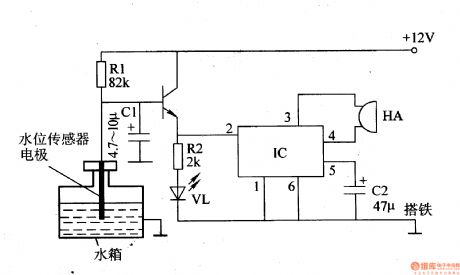
The circuit consists of water level sensor, the transistor V, resistors Rl, R2, water indication light pole tube VL, capacitors Cl, C2, integrated circuit IC and piezoelectric buzzer HA. (It is showed in picture 7-105.)
When the water level is higher than the low setting water level, VL is off and HA is noiseless
When the water level is lower than the low setting water level, the electrode of water level sensor is above water , then V is saturated and on, the high level voltage output by the emitter pole trigger VL on and also make IC at work ,then HA send out alarm.
In case of waving of the water level while driving that cause false alarm, a time delay capacitor C1 is added to the circuit . While the waving water level cause the electrode above the water instantaneously , +12 V voltage will charge C1 through R1. And because the voltage of C1 cann’t change suddenly, V cann’t be on in a sudden and there will be no false alarm. (View)
View full Circuit Diagram | Comments | Reading(1557)
Anti-theft Alarm Of Motorcycle One
Published:2011/7/29 4:44:00 Author:Felicity | Keyword: Anti-theft Alarm, Motorcycle
Work of the circuit
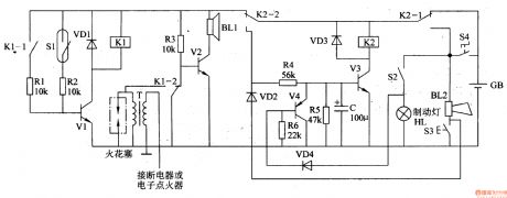
The circuit consists of trigger circuit, alarm control circuit and the reset the alarm circuit. (It is showed in picture 7-84.)
Trigger circuit consists of Mercury switches Sl, resistor cell, transistors Vl and relay Kl.
Alarm control circuit consists of the relay contacts Kl Kl-l, Kl-2, transistor V2, resistors R3 and Rl and alarm speaker BLl.
The reset the alarm circuit consists of transistors V3 and V4, the diode VD2-VD4 and relay K2.
Usually, the mercury switch S1 is off and the circuit stands by.
As soon as the theft upright the motor, the mercury switch S1 turns on to make V1 and K1 on. On one hand the normally open contact of K1-1 closes to ensure that V1 is on, on the other hand the normally close contact of K1-2 releases, and the normally open contact closes to make V2 on and BL sends out alarm, and the non-grounding terminal of the high voltage ignition coil T is connected to ground through the normally open contact of K1-2 and the motorcycle cannot start.
When the motorcycle key is plugged in and step on the brake for a while, V3 will in the on-state and the alarm will be discharged. (View)
View full Circuit Diagram | Comments | Reading(1550)
LOW_VOLTAGE_ALARM
Published:2009/7/14 21:33:00 Author:May
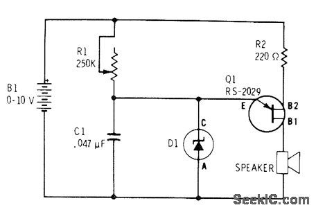
UJT relaxation oscillator produces audio tone from loudspeaker when battery voltage drops below breakdown voltage of zener. For 9-V battery, zener can be 6-V unit (Radio Shack 276-561), When input voltage drops below zener breakdown, zener stops conducting and C1 begins charging, as required for oscillation. When battery is replaced, zener breaks down and prevents C1 from charging.-F. M. Mims, Semiconductor Projects, Vol. 2, Radio Shack, Fort Worth, TX, 1976, p 43-49.
(View)
View full Circuit Diagram | Comments | Reading(0)
MULTICHANNEL_ALARM
Published:2009/7/14 21:25:00 Author:May

Half of CD4013AE flip-flop serves as latching AND gate in each channel being monitored for vervoltage, overtemperature, or any other out-of-tolerance condition that can be represented by logic 1 level applied to terminal that connects to clock inputs of all flip-flops. Any number of additional channels can be paralleled to Gammon terminals. Each channel has own transistor driver and either LED or audio alarm. Alarm condition is held until operator resets system by applying voltage to common set terminal. Article shows how to obtain additional flexibility by adding NAND and AND gates to each select input and to common alarm input.-J. C. Nichols, CM0S D Flop Makes Latching AND Gate, EDN Magazine, April20, 1974, p 89 and 91. (View)
View full Circuit Diagram | Comments | Reading(1162)
OVERVOLTAGE_ALARM
Published:2009/7/14 21:24:00 Author:May
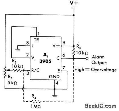
Connection shown for 3905 timer makes output go high for energizing suitable alarm when supply voltage rises above predetermined level. Timer is connected as noninverting comparator that compares its fixed voltage-comparison threshold of 2 V with fraction of supply voltage determined by setting of R1. Optional resistor R4 can be added if some hysteresis is desirable to prevent tripping of alarm by momentary fluctuations of supply.-W. G. Jung, IC Timer Cookbook, Howard W, Sams, Indianapolis, IN, 1977, p 230-231. (View)
View full Circuit Diagram | Comments | Reading(980)
POWER_FAILURE_ALARM
Published:2009/7/14 21:23:00 Author:May
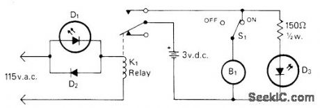
POWER-FAILURE ALARM-Buzzer sounds and red LED D3 comes on when AC power fails, as reminder that clocks will need resetting. Green LED D1 indicates that alarm is plugged in, D2 is Radio Shack 276-1103 or equivalent silicon diode. B1 is 1.5-6 VDC Radio Shack 273-004 or equivalent buzzer, and K1 is Radio Shack 275-211 or equivalent 117-VAC SPDT relay.-C. R. Graf, The Powerlarm, CQ, Feb. 1977, p 47 and 73. (View)
View full Circuit Diagram | Comments | Reading(0)
UNDERVOLTAGE_ALARM
Published:2009/7/14 20:56:00 Author:May
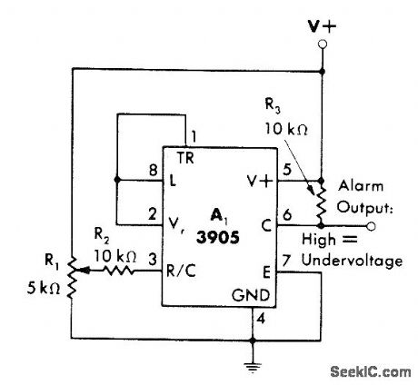
3905 timer output goes high when power supply drops below predetermined voltage level. Timer is connected as inverting comparator that compares fraction of supply voltage (as set by R1) with fixed voltage-comparison threshold of 2 V for timer. Output can be used to drive suitable alarm indicator.-W. G. Jung, IC Timer Cookbook, Howard W. Sams, Indianapolis, IN, 1977, p 230-231. (View)
View full Circuit Diagram | Comments | Reading(1281)
VOLUME_UNIT_DISPLAY_AND_ALARM
Published:2009/7/13 4:09:00 Author:May

This circuit uses two audio amplifiers, one for a microphone and one for a stereo input, to drive an LED bar-graph display, rather than a meter. When the input exceeds a certain level, an LED (#8 in this circuit) will light and also cause an alarm buzzer or some other signal to actuate. A switch is provided for source selection. (View)
View full Circuit Diagram | Comments | Reading(1353)
RAIN_ALARM
Published:2009/7/12 22:45:00 Author:May
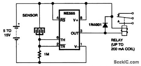
This rain-detector circuit closes the relay when water bridges the gap between the metal elecLrodes. (View)
View full Circuit Diagram | Comments | Reading(0)
TAMPER_ALARM
Published:2009/7/12 22:44:00 Author:May
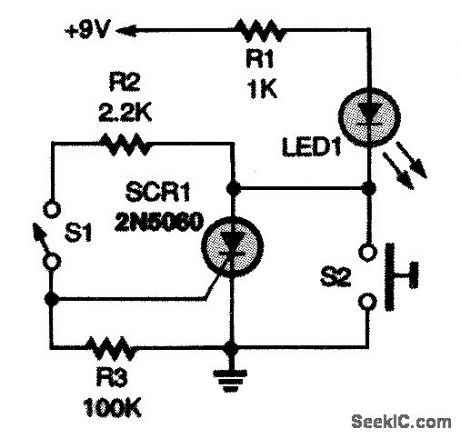
The silicon-controlled rectifier (SCR1) operates as a memory device to indicate a security breach in a room, desk drawer. safe. etc. Switch S1 can be a mechanical or magnetic switch. Position S1 in an object that you want to keep protected, making sure that the switch will close when the object is tampered with. When S1 closes, SCR1 turns on, lighting LED1. Pressing S2 resets the circuit. (View)
View full Circuit Diagram | Comments | Reading(1122)
PROPERTT_ALARM_CIRCUIT
Published:2009/7/12 22:43:00 Author:May
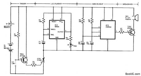
The circuit is designed to protect by means of a wire loop or mercury switch. TR1 and associated components form a switch that is biased off by the normally closed (N.C.) link. When the link is broken, TR1 conducts and triggers the thyristor (CSR1) into conduction. Consequently, the LED flasher centered around the 555 astable of IC1 causes D1 to blink. Additionally, IC2 is a monostable timer that triggers through R5/C2 and drives an audible warning device via TR2 for a period of approximately 2 min before resetting. When the audio alarm has timed out, the LED will continue to flash, and this can be cancelled by opening S1, which resets the thyristor. The quiescent current of the circuit is very low because of the high value of resistor R1. A mercury switch can be used in place of the wire link to act as an antitamper alarm, in which case care must be taken to avoid accidental contact with the mercury bead itself because it is highly toxic.
(View)
View full Circuit Diagram | Comments | Reading(1214)
CUT_PHONE_LINE_ALARM_1
Published:2009/7/12 22:31:00 Author:May
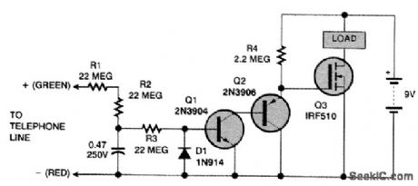
Detecting a cut phone line can be an important function of an electronic security system. UnforLunately, detecting a cut phone line isn't easy because the voltages on a normal phone line vary so rnuch. The voltage is typically 48 Vdc when the telephone is on the hook, 2 to 15 Vdc during a conversation, 90 Vac during ringing, and 200 Vdc when the telephone company is testing the line. Brief moments of 0 V are common; what you really want to detect is a voltage that goes to zero and stays there. A second restriction is that the cut phone line detector cannot draw any appreciable current. Its impedance has to be higher than 50 MΩ or the telephone company will think it's a leaky cable, Components R1, R2, R3, and C1 smooth out momentary variations in voltage so that the alarm doesn't trigger every time the telephone rings. If the voltage stays at zero for 30 s or more, the alarm should trigger. The load can be a piezo buzzer, an optocoupler, or a small relay.Because of the tiny currents it rnust detect, this circuit should be powered by its own 9-V battery, with no direct connection to the rest of the burglar alarm. Otherwise, a slight difference in ground potentials might cause the circuit to perform somewhat erratically. (View)
View full Circuit Diagram | Comments | Reading(1126)
BURGLAR_ALARM
Published:2009/7/12 22:28:00 Author:May

This burglar alarm uses either normally closed (S5 to S8) or normally open (S9 to S11) switches or a combination thereof. Activation sets latches IC1-b and IC1-c. S1 is used to disarm the circuit. IC1-d and related components drive switch Q1, which triggers timer IC2. IC2 generates a pulse, determined by R3 and C5, that energizes alarm relay RY1. S2 allows for a continuous alarm and S12 is a panic switch to sound the alarm immediately. Either a built-in buzzer (BZ1) or an external siren can be used as an annunciator. (View)
View full Circuit Diagram | Comments | Reading(0)
INTRUDER_ALARM
Published:2009/7/12 22:21:00 Author:May
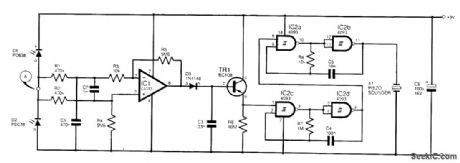
The circuit triggers a pulsed-tone alarm when anyone passes by, and several of these units can be scattered around the premises to give burglars the impression that they are being monitored! It is guaranteed to drive any burglar bananas. Two photodiodes, D1 and D2, are used as shown to ensure sensitivity over a very wide range of lightning conditions, though the circuit will be less effective in diffuse light. IC1 is connected as a differential amplifier. As thevoltage at pointA swings high, the response at pin 2 of IC1 is slowed by capacitor C1, and the voltage swings high at the output (pin 6). Capacitor C3 charges up and transistor TR1 level-shifts the signal to enable the oscillator section formed from IC2, a quad NAND Schmitt. The piezo disk X1 will pulse accordingly. C3 determines the duration of the pulsed tone and resistor R8 determines the pitch. Photodiodes D1 and D2 should be mounted a small distance apart for best effect. The circuit draws a mere 0.5 mA.
(View)
View full Circuit Diagram | Comments | Reading(0)
CUT_PHONE_LINE_ALARM
Published:2009/7/12 22:16:00 Author:May

The figure shows the schematic diagram of the phone line monitor. Note that 12-Vdc power is connected to the unit via solder pads C (positive) and G(ground) on the PC board. This power should be supplied from your home security system, since it will have battery backup, and this will be as reliable as your base security system. The input from the telephone line is fed to pads A and B. Polarity is not important to the monitor because the input is rectified by the full-wave bridge rectifer formed by diodes D3 to D6. Connecting the phone line to the phone line monitor in no way diminishes phone senrtce', and its presence on the line will be unnoticed by you and those who call you. The rectified or polarized voltage from the bridge rectifier is fed to a long-time-constant filter formed by R2 and C1. This filter includes a zener diode (D2) that limits the voltage maximum charge on C1 to 12 V during normal operation. Resistor R3 provides a high-resistance shorting path to drain the charge from C1 when there is no input voltage. This resistor sets the time delay for activating the alarm. The trigger voltage for comparator IC1-a is generated by R1 and D1. Diode Dl is a 5.1-V zener whose output is fed to the inverting input (pin 4) of IC1-a. With the inverting input at 5.1 V, any voltage above 5.1 Y on the noninverting input (pin 5) will cause the output of the comparator to go high. Since the output of IC1 is tied to the relay coil of RY1 and the other end of the relay is tied to +12 Vdc, the relay coil is not energized. When the voltage from the input filter drops below 5.1 V, the out-put of IC1-a goes low and energizes the relay. The contacts of RY1 (either the normally open set or the normally closed set) could also be used to trigger the home's security system.
(View)
View full Circuit Diagram | Comments | Reading(1349)
AUTOPILOT_COMPARATOR_ALARM
Published:2009/7/11 4:39:00 Author:May

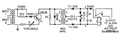
Actives alarm or disengages autopilot when signals from dual accelerometers differ apperciably.indicating malfunction.-C. W. McWilliams, Designing Safety Into Automotic Pilot Sys-tems, Electronics, 31:45, p69-71. (View)
View full Circuit Diagram | Comments | Reading(754)
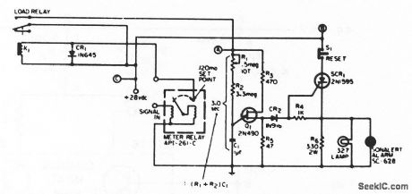
RESISTANCE_TRIGG_FRED_ALARM
Published:2009/7/10 1:26:00 Author:May

Silicon controlled switch is triggered when temperature-, light-, or radication-sensifive resistor Rs up to meter drops below vadue of preset potentiometer.Interchanging Rs and potentiometer will trigger alarm on increase in sensing resistor.- Transi stor Manual, Seventh Edition, General Electric Co., 1964, p 425. (View)
View full Circuit Diagram | Comments | Reading(1064)
LAMP_BURNOUT_ALARM
Published:2009/7/9 23:49:00 Author:May
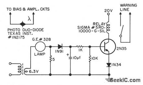
Used when photocells and lamps are employed to detect end of magnetic tape, lood point, or bad spot.Failure of lamp can cause serious trouble in magnetic tape handler. With circuit showm, when lamp burns out, transistor can no longer energize relay, and relay contact doses to actuate alarm at computer console.-J. E. Kienle and R. W. Wooldridge, Photocell Lamp Burnout Warning Circuit, EEE, 10:8, p 27-28. (View)
View full Circuit Diagram | Comments | Reading(922)
MULTIPLE_INPUT_ALARM
Published:2009/7/9 23:44:00 Author:May
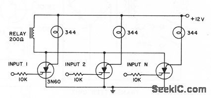
Any of several inputs will pull in common alarm relay, with corresponding lamp giving visual indication of triggered circuit. For higher-current laps, use 3N81 silicon controlled swilches.- Iransistor Manual, Seventh Edition, General Electric Co., 1964, p 425.
(View)
View full Circuit Diagram | Comments | Reading(1053)
GYRO_FAULT_ALARM
Published:2009/7/9 23:40:00 Author:May
Circuit sounds alarm if gyro wheel is locked up, as indicated by input signed remaining at high current or voltage level for longer than preset interval.Circuit can also be used as pulse-level discrimincttor.-R. L. Sazpansky, Pulse-Level Discriminator and Fault Indicator, EEE, 13:8, p 68. (View)
View full Circuit Diagram | Comments | Reading(983)
| Pages:6/18 123456789101112131415161718 |
Circuit Categories
power supply circuit
Amplifier Circuit
Basic Circuit
LED and Light Circuit
Sensor Circuit
Signal Processing
Electrical Equipment Circuit
Control Circuit
Remote Control Circuit
A/D-D/A Converter Circuit
Audio Circuit
Measuring and Test Circuit
Communication Circuit
Computer-Related Circuit
555 Circuit
Automotive Circuit
Repairing Circuit