
Alarm Control
Index 8
BACK_UP_ALARM
Published:2009/7/9 4:40:00 Author:May
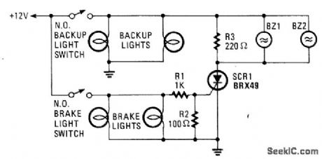
The brake lights of the automobile trigger this circuit on and off. This saves the annoyance of the alarm when it is not needed. (View)
View full Circuit Diagram | Comments | Reading(1210)
LOW_CURRENT_SIMPLE_CMOS_ALARM
Published:2009/7/9 4:39:00 Author:May
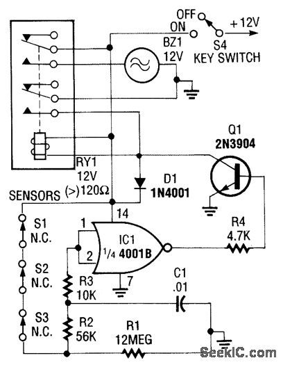
This CMOS-aided alarm draws only 1μA standby current. An open sensor allows IC1 to bias Q1 on, activating RY1. (View)
View full Circuit Diagram | Comments | Reading(639)
SINGLE_IC_ALARM
Published:2009/7/9 4:36:00 Author:May

With a single IC, you can build a simple, reliable auto burglar alarm or a similar alarm. See (a) for the timing information for the alarm circuit in (b).
When you leave your vehicle, flip the arming switch and close the door,behind you to arm the device.Subsequent opening of an entrance triggers both timers. After the expiration of the entry delay timer, the alarm sounds for a time that is determined by the second timer.
The value of R should be less than 1 kΩ. If you use an incandescent lamp instead of a resistor, you get an extra function-an open-entrance indicator. By keeping the resistance low, you avoid false tripping should water collect under the hood.
If your door switch connects the courtesy light to 12 V rather than to ground, use a single transistor as an inverter at the input. Although this circuit's simplicity has its drawbacks, you can add more features, such as no-entry delays for the hood and trunk, and retripping when doors remain open. (View)
View full Circuit Diagram | Comments | Reading(835)
AUTOMATIC_ARMING_AUTO_ALARM
Published:2009/7/9 4:20:00 Author:May

The circuit automatically turns on when the car is turned off. It gives you a variable time to get out and lock up, and also provides a variable time delay to get in and start the car.
The 555 oscillator/timers are always powered down when the car is on. That keeps the alarm from going off while you're driving. As soon as the car is turned off, Q2 switches off and shunts power to U1. When that happens, U1 immediately sends its output high, keeping Q3 on, and thereby prevents power from returning to U2.
Transistor Q2 also sends power to Q3's collector to be used only when U1 has completed its timing cycle. When U1 has finished, it turns Q3 off, which in turn activates Q4, and sends power to the balance of the circuit. That timing period was the time needed to get out of the car. LED1 indicates that the system is disarmed and LED2 indicates that the system is armed.
At this point, U2 whits for a trigger pulse from the car's door switches or dome light. A positive impulse at the 4011's input sends a negative trigger pulse to the first stages of U2, which is connected as a cascading timer. The first stage's output becomes high for a time to allow the car to be turned on.
If that does not happen, the first stage's output lowers, which sends a low trigger pulse to the second stage. The second stage then sends its output high, turning on Q5, which sounds the alarm for a given time. Once that time has elapsed, the alarm is shut off by a low output to Q5 and the system is reset. If the car door is closed or a second door opened while the alarm is sounding, the first stage retriggers and pre-pares to extend the ON-time of the alarm.
The cascading or counting action continues until the car is left alone. You can add a switch on the positive supply rail at J3 to override and silence the alarm, if (for example) you plan to work on the car.Switch S1 is a normally closed type that is built into the case of the alarm; S1 is pushed to the open posi-tion when the case is mounted flush with a surface. Any attempt to remove the alarm will sound the alarm. (View)
View full Circuit Diagram | Comments | Reading(890)
WATER_LEAK_ALARM
Published:2009/7/9 3:12:00 Author:May
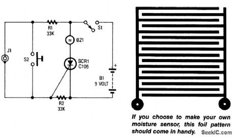
A sensor connected to J1 causes SCR1 to conduct, which sounds buzzer BZ1. The sensor is a PC-board foil pattern grid. Several sensors can be wired in parallel for increased coverage or to monitor sev-eral places simultaneously. (View)
View full Circuit Diagram | Comments | Reading(963)
RAIN_ALARM
Published:2009/7/9 3:00:00 Author:May
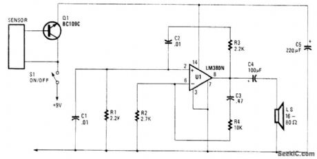
This rain sensor causes Q1 to conduct when conductive liquid (rainwater, etc.) applies bias to its base.This bias triggers LM380N oscillator and causes LS to emit a tone. (View)
View full Circuit Diagram | Comments | Reading(0)
FLOOD_ALARM
Published:2009/7/9 2:57:00 Author:May


Using a few bipolar transistors, this circuit acts as a flood alarm. When liquid touches the probes,leakage current biases Q1, Q2, and Q3 (a dc-cou pled amplifier) into conduction, which activates the relay. The contacts can be hooked into the alarm system. (View)
View full Circuit Diagram | Comments | Reading(0)
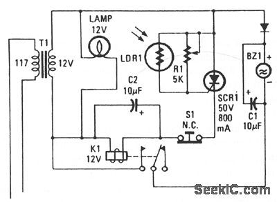
STROBE_ALARM
Published:2009/7/9 1:55:00 Author:May

This strobe gives a visual indication of a sensor input. The input signal causes U1, a light dependent resistor, to charge C1 and C3 through R4. When NE1 fires, C3 discharges into SCR1, which triggers it and causes C2 to discharge through trigger transformer T1, which triggers Flashlamp FL1. The 330-V supply should have about 50 to 100 μF output capacitance. L1 supplies about 25-mH inductance to prolong the flash and the life of FL1. (View)
View full Circuit Diagram | Comments | Reading(1384)
Storehouse temperature measurement alarm circuit diagram
Published:2011/8/3 2:41:00 Author:Rebekka | Keyword: Storehouse temperature measurement alarm

View full Circuit Diagram | Comments | Reading(669)
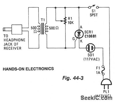
RECEIVER_SIGNAL_ALARM
Published:2009/7/7 8:06:00 Author:May
View full Circuit Diagram | Comments | Reading(758)
SECURITY_DOOR_AJAR_ALARM
Published:2009/7/7 7:27:00 Author:May
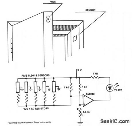
In operation, the TL3019 device will activate, or become low, when a south pole of a magnet comes near the chip face of the device. The example shows five doors. Each door has a magnet embedded in its edge with the south pole facing the outer surface. At the point where the magnet is positioned with the door closed, a TL3019 sensor is placed in the door jamb. With the door closed, the Hall devices will be in a logic low state. This design has five doors and uses five TL3019 devices. Each TL3019 has a 4-KΩ resistor in series and all door sensor and resistor sets are in parallel and connected to the inverting input of an LM393 comparator. With all doors closed, the effective resistance will be about 800 0 and produce 2.2 V at the inverting input. The noninverting input goes to a voltage divider network which sets the reference voltage. The 1.5-KΩ potentiometer is adjusted so the indicator goes out with all doors closed. This will cause 2.35 V to appear at the noninverting input of the comparator. When a door opens, the voltage at the inverting input will go to 2.5 V which is greater than VREF, and the LED will light. A large number of doors and windows can be monitored with this type of circuit. Also, it could be expanded to add an audible alarm in addition to the visual LED. (View)
View full Circuit Diagram | Comments | Reading(1083)
SCR_SMOKE_ALARM
Published:2009/7/7 7:15:00 Author:May
View full Circuit Diagram | Comments | Reading(715)
TIMER_WITH_ALARM_
Published:2009/7/7 3:58:00 Author:May
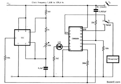
The circuit has two ranges: secs to 5 mins and 1 min to 80 mins.It can be powered by a 9-V battery.With the LED connected as shown a reasonable frequency of flashing occurs throughout the range of operation.This circuit is reset when S2 is closed. (View)
View full Circuit Diagram | Comments | Reading(885)
ADJUSTABLE_THRESHOLD_TEMPERATURE_ALARN
Published:2009/7/7 2:35:00 Author:May

When R1 increases as temp decreases, the output of IC1 goes positive, turning on Q1. Q1 conducts and causes Q2 to conduct, turning on the audible alarm. The threshold is set with potentiometer R2. (View)
View full Circuit Diagram | Comments | Reading(1177)
TEMPERATURE_ALARM
Published:2009/7/7 2:34:00 Author:May

The mute pin of this dual audio amplifter is so used as the trigger for a one chip high-temperature alarm. One-half of the IC is connected as an oscillator and the other boosts the audio alarm outputs to 10W. (View)
View full Circuit Diagram | Comments | Reading(982)
FLOOD_ALARM_OR_TEMPERATURE_MONITOR
Published:2009/7/6 9:17:00 Author:May

Filtered 15 Vdc is applied to a series circuit consisting of thermistor R2 and parallel combination of resistors R1 and R3. Transistor Q1 acts as a switch whose state is determined by the setting of potentiometer R3, which is first set so just enough current flows into the base to switch on when the thermistor is in contact with air. When the resistance of the thermistor decreases, the voltage at the base of Q1 rises. When the base current reaches the preset level, the transistor conducts and passes current through the reed relay coil, closing the reed relay contacts. Current at the base of transistor Q1 is determined by the environment into which the termistor is inserted. (View)
View full Circuit Diagram | Comments | Reading(773)
MISSING_PULSE_ALARM
Published:2009/7/6 6:15:00 Author:May
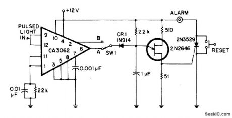
Developed for sensing missing light pulses or detecting absence of object on moving conveyor belt. CA3062 com bination light sensor and amplifier detects light pulses synchronized to 60-Hz line. With SW1 at A, each pulse resets 20-ms timing network of 2N2646 UJT at 16.7-ms intervals, preventing UJT from firing. If light beam is interrupted by object, UJT is allowed to fire and trigger 2N3529 SCR that turns on alarm. With SW1 at B, circuit detects interruptions in steady light beam and sounds alarm only when interruption does not occur.-J. F. Kingsbury, Double Duty Photo Alarm, EDN|EEE Magazine, May 15, 1971, p 51. (View)
View full Circuit Diagram | Comments | Reading(1668)
VARYING_FREQUENCY_WARNING_ALARM
Published:2009/7/6 5:50:00 Author:May

The output frequency changes continuously. Low frequency oscillator (Q1) modulates high frequency oscillator Q2 and its associated timing capacitor.
(View)
View full Circuit Diagram | Comments | Reading(699)
WARBLE_TONE_ALARM
Published:2009/7/6 5:30:00 Author:May

The circuit generates a warble-tone alarm signal that simulates the sound of a British police siren. IC1 is wired as an alarm generator and IC2 is wired as a 1 Hz astable multivibrator. The output of IC2 is used to frequency modulate IC1 via R5. The action is such that the output frequency of IC1 alternates symmetrically between 500 Hz and 440 Hz, taking one sound to complete each alternating cycle. (View)
View full Circuit Diagram | Comments | Reading(1894)
WAILING_ALARM
Published:2009/7/6 5:28:00 Author:May


This circuit simulates the sound of an American police siren. IC2 is wired as a low frequency astable that has a cycling period of about 6 seconds. The slowly varying ramp waveform on C1 is fed to pnp emitter follower Q1, and is then used to frequency modulate alarm generator IC1 via R6. IC1 has a natural center frequency of about 800Hz. Circuit action is such that the alarm output signal starts at a low frequengy, rises for 3 seconds to a high frequency, then falls over 3 seconds to a low frequency again, and so on ad infinitum.
(View)
View full Circuit Diagram | Comments | Reading(1566)
| Pages:8/18 123456789101112131415161718 |
Circuit Categories
power supply circuit
Amplifier Circuit
Basic Circuit
LED and Light Circuit
Sensor Circuit
Signal Processing
Electrical Equipment Circuit
Control Circuit
Remote Control Circuit
A/D-D/A Converter Circuit
Audio Circuit
Measuring and Test Circuit
Communication Circuit
Computer-Related Circuit
555 Circuit
Automotive Circuit
Repairing Circuit