
Alarm Control
Index 17
Frost Alarm Circuit (2)
Published:2011/5/12 2:19:00 Author:Robert | Keyword: Frost, Alarm
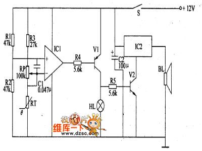
The forst alarm circuit introduced in this example can give the sound and light signal immediately when the frost coming to remind the workers to prepare for anti-frost in time. This device can be widely used in the areas such as agriculture and mining and so on.The circuit's working principle is shown below.This frost alarm circuit is made up by the frost detecting circuit and sound-lignt alarm circuit which is shown in the picture below. The frost detecting circuit is made up by the thermistor RT, resistance R1~R3, potentiometer RP, capacitor C and operational amplifier integrated circuit IC1.The sound-light alarm circuit is made up by resistance R4, R5, transistor V1, V2, alarm alarm indicator lamp HL, sound effect integrated circuit IC2 and speaker BL.When there is no frost, the atmospheric temperature is relatively higher. RT is in low-resistance mode, IC in-phase input port's voltage is higher than the out-phase input port's, and it outputs high voltage level to make V1 and V2 disconnected. So HL does not light and IC2 does not work, BL has no sound.In case of the frost coming, the atmospheric temperature is low and the RT's resistance would rise to make the IC's out-phase input port voltage higer than the in-phase input port's voltage and make its output port's voltage be low voltage level. So V1 and V2 is connected and HL would light, IC2 is electrified to work and BL would have the alarm sound.
(View)
View full Circuit Diagram | Comments | Reading(939)
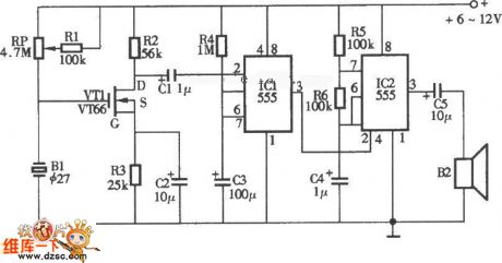
lOW sound and light siren circuit diagram
Published:2011/5/6 4:24:00 Author:Ecco | Keyword: lOW, sound , light s, iren

lOW sound and light siren circuit diagram is shown as the chart. The circuit can produce high-intensity alarm which can be used as anti-theft alarm. When the power is switched on the alarm system, VD1 is flashing, while it outputs the pulse square wave on R1 resistor, after gets triangular wave by passing R2, VD2, C1 network, IC is a 555 time base circuit, and it forms voltage-controlled oscillator. R3, R4 and C3 are the timing components. The output variable tone signal is amplified by the VT under the control of the triangular wave to promote the speaker, the output power closes to l0W. Adjusting R1 can change the triangle wave amplitude of C1, changing W1 can adjust the volume. Figure (b) is printed installation diagram.
(View)
View full Circuit Diagram | Comments | Reading(1571)
Frost Alarm Circuit
Published:2011/5/8 6:45:00 Author:Robert | Keyword: Frost, Alarm
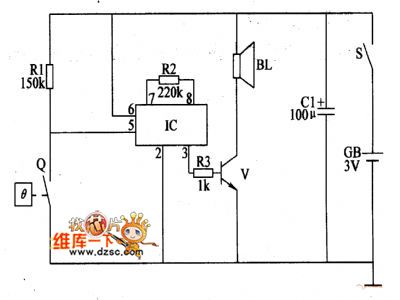
In the natural disasters, the frost's damage to crops is very serious which can have a direct impact to crop yield.The frost alarm circuit introduced in this picture, can have the alarm sounds when the environmental temperature is lower than 1℃ to remind the farmers to prepare for anti-forst in time.The circuit's working principle is shown below.This frost alarm circuit is made up by power circuit, temperature monitoring control circuit and alarm circuit which is shown in the picture below. The power circuit is made up be battery GB, power switch S and electron-contact thermometers Q.The alarm circuit is made up by the sound effect integrated circuit IC, resistance R2, R3, transistor V and speaker BL.When the power switch S is connected, the alarm circuit is in alert mode. When the environmental temperature is higher than 1℃, the Q's electrical thermal control contactor is disconnected and the alarm circuit is not working and BL has no sound. When the environmental temperature decrease to 1℃ or less, the Q's electrical thermal contactor is connected to trigger the IC to work. The sound effect electrical signal from the IC's 3 foot is amplified by V to drive the BL to play the alarm sound.V uses 59013 or CW9561 type sound effect integrated circuit.
(View)
View full Circuit Diagram | Comments | Reading(905)
Smoke detection alarm circuit diagram
Published:2011/5/5 20:32:00 Author:Ecco | Keyword: Smoke , detection , alarm circuit
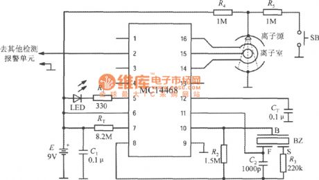
The smoke detection alarm circuit composed of MC14468 Ionic smoke detection alarm integrated circuit is shown as the chart. The device uses 9V laminated battery. RT and CT are respectively oscillation resistor and oscillation capacitor. LED is Light-emitting diode, R1 is the current limit resistor. BZ is the piezoelectric ceramic buzzer, which consists of three electrodes, namely B pole, F pole and S pole. Ion source is americium 241 (Am241), the radioactive intensity is as low as 0.8Ci (or 0.8 micro-Curie), and it will not cause harm to humans and pollute the environment. Ion source is installed at the top of the ion chamber. R4 and R5 are the partial pressure resistors. SB is self-test button. The source connects to +9 V voltage under normal state, when it is connected to SB, the voltage is +4.5 V, then it can simulate the case of detecting smoke. MC14468 can be connected to other test unit circuits through pin 2. (View)
View full Circuit Diagram | Comments | Reading(1527)
Door And Window Infrared Monitoring Anti-Theft Alarm Circuit
Published:2011/5/5 9:30:00 Author:Robert | Keyword: Door, Window, Infrared, Monitoring, Anti-Theft, Alarm
Door And Window Infrared Monitoring Anti-Theft Alarm Circuit is shown below:
(View)
View full Circuit Diagram | Comments | Reading(1811)
Open circuit, short circuit anti-theft alarm circuit diagram
Published:2011/5/2 22:55:00 Author:Ecco | Keyword: Open circuit, short circuit , anti-theft , alarm circuit
AC driving light-emitting diodes can make higher output optical power, the driving circuit form is shown as the chart. The two LEDs are connected reversely in parallel, so that the positive and negative half-cycle of power have a light-emitting diode to display. (View)
View full Circuit Diagram | Comments | Reading(1154)
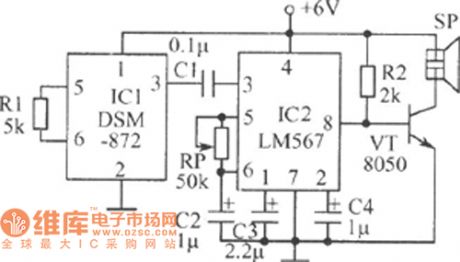
Control and alarm circuit diagram composed of SGZ07 sound and light alarm IC
Published:2011/4/28 22:59:00 Author:Ecco | Keyword: Control , alarm , sound , light, alarm IC
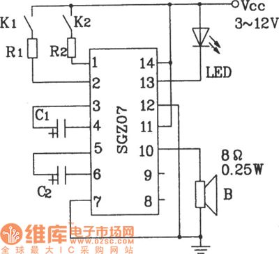
Control and alarm circuit diagram composed of SGZ07 sound and light alarm IC.
In the figure, the circuit can work in dual-band sound, light alarm circuit by controlling the K1, K2. If the R1, R2 in the circuit are changed in the corresponding thermal resistor (measured value), it can achieve temperature control and alarm circuit.
(View)
View full Circuit Diagram | Comments | Reading(925)
Mashgas, coal gas detection and alarm circuit
Published:2011/4/28 22:56:00 Author:Ecco | Keyword: Mashgas, coal gas, detection , alarm , monolithic, integrated circuit

Mashgas, coal gas detection and alarm circuit composed of CH217 monolithic gas detection alarm integrated circuit.
R1 in the figure is the gas sensing probe, the resistance reduces linearly with gas concentration arbitrarily increasing, RP3 is used to adjust the amplifier output, R6, R7 extract both forecasting and risk reference signal voltage.
(View)
View full Circuit Diagram | Comments | Reading(956)
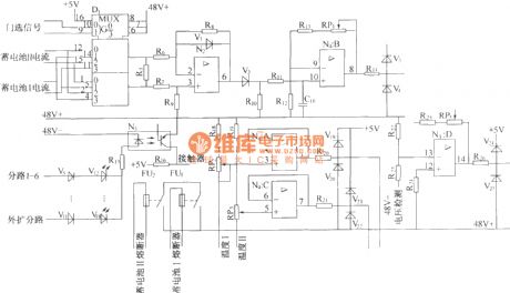
ZKB8711 controlled alarm IC for constant temperature automatic control alarm circuit diagram
Published:2011/4/28 20:29:00 Author:Ecco | Keyword: controlled , alarm , IC , constant temperature , automatic control , alarm
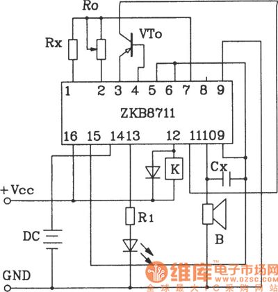
ZKB8711 controlled alarm IC for constant temperature automatic control alarm circuit.
ZKB8711 can be used for temperature control, light control, humidity control, rain and harmful gas detection and alarm control and so on, it has the advantages of several functions, few external components, easy making and so on.
(View)
View full Circuit Diagram | Comments | Reading(1410)
Smoke alarm circuit composed of MC145010 photoelectric smoke detection alarm integrated circuit
Published:2011/4/28 2:21:00 Author:Ecco | Keyword: Smoke alarm circuit, photoelectric, smoke detection , alarm , integrated circuit

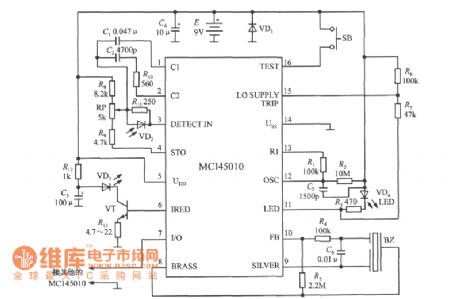
Smoke alarm circuit composed of MC145010 photoelectric smoke detection alarm integrated circuit is shown as the chart. It uses 9V laminated battery. R2, C3 are respectively oscillation resistor and capacitor oscillator, the clock cycle is determined by the follow formula:
(View)
View full Circuit Diagram | Comments | Reading(1809)
Infrared burglar alarm circuit controlled by SCM
Published:2011/4/6 5:32:00 Author:may | Keyword: Infrared burglar alarm, SCW
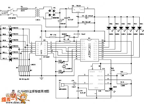
diagram: Infrared burglar alarm circuit controlled by SCM (View)
View full Circuit Diagram | Comments | Reading(1905)
Sound Control Alarm Circuit
Published:2011/4/23 3:27:00 Author:Robert | Keyword: Sound Control, Alarm
Sound Control Alarm Circuit is shown above. (View)
View full Circuit Diagram | Comments | Reading(667)
Power failure alarm circuit
Published:2011/4/18 20:33:00 Author:Ecco | Keyword: Power failure , alarm circuit
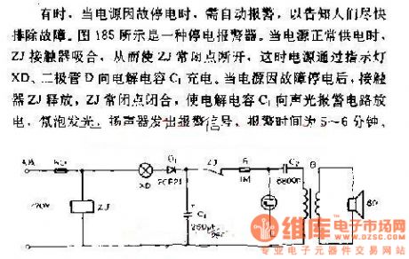
Sometimes, when the power is black out for some reasons, it needs to alarm automatically to inform people overcoming the breakdown as soon as possible. Figure 185 shows a power failure alarm. When power supply works normally, ZJ contactors pull in, so that the ZJ normal closed contact cuts off, then power is charging by the electrolytic capacitor C1 between the lights XD and diode D. When the power is black out for some reasons, ZJ contactors release, so that electrolytic capacitor C1 discharges to the sound and light alarm circuit, neon light bulbs turn on, speakers emit alarm signals, the alarm time is 5 to 6 minutes.
(View)
View full Circuit Diagram | Comments | Reading(758)
Simple combustible gas alarm circuit
Published:2011/4/11 23:54:00 Author:Jessie | Keyword: Simple, combustible gas, alarm
View full Circuit Diagram | Comments | Reading(629)
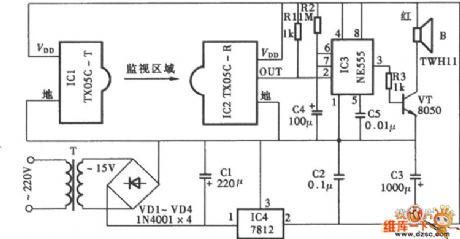
NE555 alarm circuit diagram
Published:2011/4/17 20:36:00 Author:Ecco | Keyword: alarm circuit
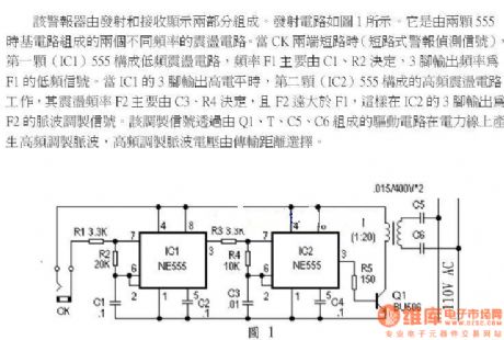
The alarm is composed of two parts of the transmitting and receiving. Transmitting circuit is shown in Figure 1. It consists of two vibration temperature circuits with different frequencies and they are composed of two 555 time-base circuits. When the two ends of CK are in short circuit, the first(IC1) 555 constitutes a low-frequency shock temperature circuit, the frequency F1 is mainly decided by C1, R2, the output frequency of pin 3 is the low-frequency signal of F1. When the output of pin 3 is in high level, the second (IC2) 555 constitutes a high-frequency shock temperature circuit, the frequency F2 is mainly decided by C3, R4, and F2 much higher than F1, so the output of pin 3 is the pulse modulated signal of F2. The modulation signal throughs the driving circuit composing of Q1, T1, C5, C6 and produces high frequency modulation pulse on the power line, the voltage of high frequency modulation pulse is decided by transmission distance.
(View)
View full Circuit Diagram | Comments | Reading(1308)
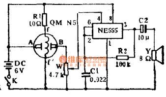
The alarm circuit diagram of miner light
Published:2011/4/14 21:13:00 Author:Ecco | Keyword: alarm circuit , miner light
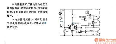
In the circuit, the batteries of miner's lamp is used as power supply and installed in the mine cap. When the gas is over the limit, the light bulb will automatically flash with the alarm. This circuit uses few components, it has no impact on the miner's work, it has the advantages of low cost, adjustable alarm points, easy to carry. (View)
View full Circuit Diagram | Comments | Reading(656)
The alarm circuit diagram for safety box and other metal objects
Published:2011/4/14 21:25:00 Author:Ecco | Keyword: alarm circuit , safety box , metal objects
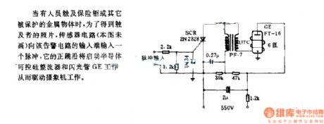
When someone touches the safety box or other protected metal objects, in order to get the photo of the toucher, the sensor circuit inputs a pulse to the alarm circuit, and its positive edge will start the semiconductor and thyristor flash GE, then driving the camera work.
(View)
View full Circuit Diagram | Comments | Reading(1097)
Loss pulse alarm circuit
Published:2011/4/13 21:25:00 Author:Nicole | Keyword: Loss pulse, alarm
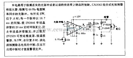
This circuit is used to test missing light pulse or the shortages of goods in sport transport tape. CA3062 combined photodetector and amplifier, it can test the light pulse which is synchronous with 60Hz power supply frequency. When switch SW1 is in A, each pulse is as 16.7ms interval to reset the 20ms timing network of 2N2646 unijunction transistor, to prevent unijunction transistor from triggering, and to trigger 2N2529 SCR turn on alertor. When SW1 is in B, this circuit interrupts detection steady light beam, the alertor alarms only in the case of without interruption. (View)
View full Circuit Diagram | Comments | Reading(802)
ZP200400II monitor alarm interface circuit
Published:2011/3/29 20:19:00 Author:may | Keyword: monitor alarm interface
View full Circuit Diagram | Comments | Reading(580)
The alarm circuit controlling by intensity of usable light
Published:2011/4/8 2:33:00 Author:Ecco | Keyword: alarm circuit , controlling , intensity , usable light
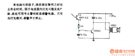
The circuit is available for hunters, fishermen when working at dawn, because the light from flashlights or inside can trigger circuit, it is also used as a fire and burglar alarm circuit. Only the lights are off, the alarm can stop.
(View)
View full Circuit Diagram | Comments | Reading(603)
| Pages:17/18 123456789101112131415161718 |
Circuit Categories
power supply circuit
Amplifier Circuit
Basic Circuit
LED and Light Circuit
Sensor Circuit
Signal Processing
Electrical Equipment Circuit
Control Circuit
Remote Control Circuit
A/D-D/A Converter Circuit
Audio Circuit
Measuring and Test Circuit
Communication Circuit
Computer-Related Circuit
555 Circuit
Automotive Circuit
Repairing Circuit