About SeekIC | Services | Payment | Advertisements service | Contact Us | Links
© 2008-2012 SeekIC.com Corp.All Rights Reserved.

Published:2009/6/23 4:41:00 Author:Jessie
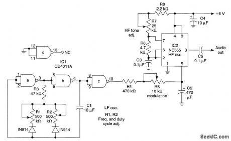
IC1 is an LF oscillator that is variable in attack and decay time with RI and R2. The LF output modulates HI' oscillator IC2. R5 varies the modulation depth. By proper control adjustment, sirens of various types can be simulated. (View)
View full Circuit Diagram | Comments | Reading(1)
Published:2009/6/23 4:39:00 Author:Jessie
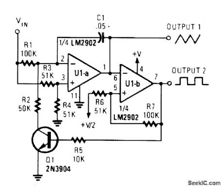
This circuit gtves both triangle-and scluarewave outputs,The frequency range IS determined by C1 (View)
View full Circuit Diagram | Comments | Reading(3675)
Published:2009/6/23 4:38:00 Author:Jessie
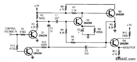
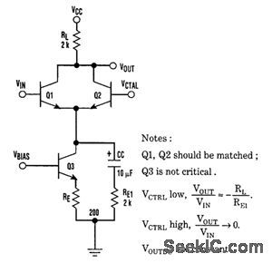
A dc control voltage varies the effective network C4/C3/C1 and R12/R3. Q2/Q3 are the oscillator transistors. (View)
View full Circuit Diagram | Comments | Reading(852)
Published:2009/6/23 3:59:00 Author:May
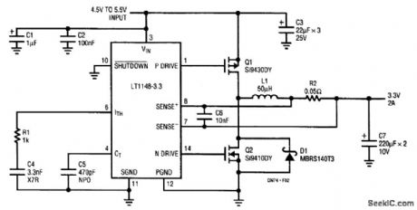


For the LT1129-3.3, dissipation amounts to a little under 1.5 W at full output current. The 5-lead surface-mount DD package handles this without the aid of a heatsink, provided that the device is mounted over at least 2500 mm2 of ground or power-supply plane. Efficiency is around 62%; dissi-pation in linear regulators becomes prohibitive at higher current levels, where they are supplanted by high-efficiency switching regulators. The synchronous buck converter is implemented with an LTC1148-3.3 converter. The LTC1148 uses both Burst ModeTM operation and continuous, constant off-time control to regulate the output voltage, and maintain high efficiency across a wide range of output loading conditions. (View)
View full Circuit Diagram | Comments | Reading(0)
Published:2009/6/23 3:56:00 Author:May
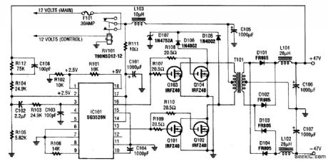
This circuit protects an IC regulator against various fault conditions. (View)
View full Circuit Diagram | Comments | Reading(0)
Published:2009/6/23 3:55:00 Author:May
This circuit protects an IC regulator against various fault conditions. (View)
View full Circuit Diagram | Comments | Reading(0)
Published:2009/6/23 3:43:00 Author:May
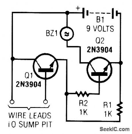
A common collector amplifier drives a 2N3904 switch to sound alarm BZ1. The wire leads to wa-ter sensor or surnp pit, level switch, etc. and used to allow the alarm to operate and be mounted in a dry place. (View)
View full Circuit Diagram | Comments | Reading(0)
Published:2009/6/23 3:42:00 Author:May
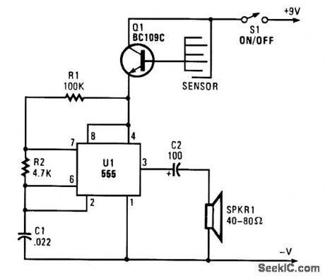
When sensor gets wet, it conducts, forward-biases Q1, and activates audio oscillator U1. A tone is heard from the speaker. (View)
View full Circuit Diagram | Comments | Reading(0)
Published:2009/6/23 4:32:00 Author:Jessie
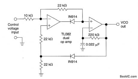
This circuit uses a dual operational amplifier (TL082) to form a voltage-controlled oscillator (VCO). With the component values shown, the output-frequency range is 100 Hz to 10 kHz when the input control voltage is between 0.05 and 10 V. (View)
View full Circuit Diagram | Comments | Reading(8044)
Published:2009/6/23 3:38:00 Author:May
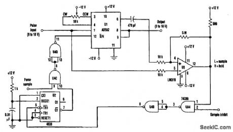
The input pulse is fed into the sample-and-hold amplifier (an inexpensive AD582), as well as the comparator U3. The SHA's output also is fed into the comparator. If the input pulse is higher in am-plitude than the SHA's output, the comparator output goes low and the 4538 one-shot produces a l0-ps pulse that is fed back to cause the SHA to sample and then hold the voltage. Subsequent input voltages that are less than the held value won't cause the one-shot to fire again.Gates U4A and U4B are used to inhibit the sampling when necessary. Gates U4C and U4D, at the one-shot's output, can force the AD 582 into the sample mode. This feature is useful to reset the output to zero by forcing a sample when the input to the AD582 is zero. The polarity of the peak-hold circuit can be easily changed from positive-to-negative peak hold by reversing the inputs of the comparator. (View)
View full Circuit Diagram | Comments | Reading(0)
Published:2009/6/23 3:23:00 Author:May
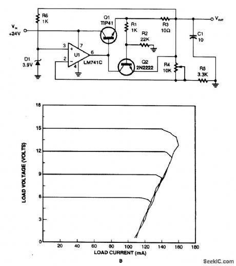
This regulator uses the drop across R3 to sense current draw, turning on Q2, removing drive from Q1, and lowering the output voltage. Limiting occurs when Q2 has 0.65 V across the base-emitter junction. This circuit has foldback characteristics as seen from the figure. (View)
View full Circuit Diagram | Comments | Reading(1)
Published:2009/6/23 3:19:00 Author:May
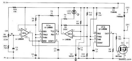
The circuit has a duty-cycle generator that will produce an output varytng from fully off to fully on and pulses of any duty cycle in between the two extremes.This method of operation is called PWM (pulse zuidth moduhtion) The circuit can be fed fromany dc supply source of between 10 to 15 V Half of an LM556 dual oscillator/timer and U2 a(1/4 of an LM339 quad comparator) combine to form a voltage to-pulse-width converter The first half of thedual os dilator/timer(U1-a) is configured as an astable oscillator,generating a continuously oscillating ramp voltage Op amp U2-a compares the voltage at its noninverting input (pin 5)—which is connected to pins 2 and 6 of U1-a—to the voltage at its inverting input(pin 4) The op amp will producea low output f R1’s wiper voltage lb higher than the instantaneous voltage that is present at pins 2 and 6 of U1-a,The output of U2-a at pin 2 will have an on/off ratio that is proportional to the voltageat R1's wiper.The output of U2-a is fed to U1-b,which is used to buffer the signal,The low-impedance,pulsedoutput of U1-b at pin 9 is fed to the gate of MOSFET Q1,driving it on or off The circuit also has apower-input detector,built around U2-band and LED1. If the input power is OK,LED1 will shut off.Diode D1 is used to Suppress the reverse voltage spikes that are generated by inductive loads during turn off;without that diode,the MOSFET might be destroyed.If the circuit will not be usedto drive inductive loads(motors),D1 can be eliminated. (View)
View full Circuit Diagram | Comments | Reading(2190)
Published:2009/6/23 3:43:00 Author:Jessie
A common collector amplifier drives a 2N3904 switch to sound alarm BZ1. The wire leads to wa-ter sensor or surnp pit, level switch, etc. and used to allow the alarm to operate and be mounted in a dry place. (View)
View full Circuit Diagram | Comments | Reading(1631)
Published:2009/6/23 3:04:00 Author:May
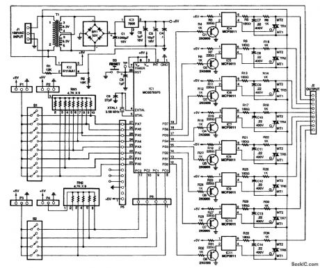
This circuit is used to vary the power delivered to a 120-Vac load under software control. A 68705 micro controller can control eight discrete power triacs, each of which delivers power in 82 smoothly graduated steps, ranging from 0 to 97% of full power. The value delivered to one channel is independent of the value delivered to any other channel. Loads can include light displays, universal motors, heaters, and other appliances.The power level is set by software, not a potentiometer. The software includes a basic set of routines for processing interrupts and setting the power level. The software also includes five test and demonqtration routines for putting the circuit through its paces. Moreover, there's plenty of room to add your own routines to the 68705's built-in EPROM.The basic circuit is simple, yet versatile enough to accept inputs from on-board DIP switches; al-ternatively, the inputs can be driven from a microcomputer bus or parallel port, or a stand-alone device with TTL-compatible outputs. There are 12 input bits to set modes and specify values. (View)
View full Circuit Diagram | Comments | Reading(0)
Published:2009/6/23 3:42:00 Author:Jessie
When sensor gets wet, it conducts, forward-biases Q1, and activates audio oscillator U1. A tone is heard from the speaker. (View)
View full Circuit Diagram | Comments | Reading(1950)
Published:2009/6/23 3:35:00 Author:Jessie
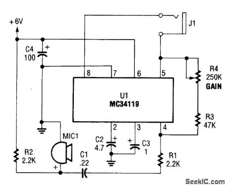
The first amplifier circuit is a bird phone. In this circuit, the electret mike (MIC1) is mounted in the neck of a large plastic funnel. The amplifier, built around an MC34119 (which is available from D.C. Electronics, P.O. Box 3203, Scottsdale, AZ 85271-3203; Tel. 800-467-7736, and elsewhere), is then placed outside of the funnel with the pick-up facing a nearby bird feeder. The output of the amplifier is then connected to a 16-Ω speaker.
The amplifier's voltage gain is determined by the values of the input resistor (R1) and the feed-back resistor (R3 and R4, respectively). The differential gain of the amplifier is given by: R3 + R4/R1 × 2. With the component values shown, the maximum voltage gain is about 270. This permits listening to the activity at the bird feeder. (View)
View full Circuit Diagram | Comments | Reading(2881)
Published:2009/6/23 2:46:00 Author:May
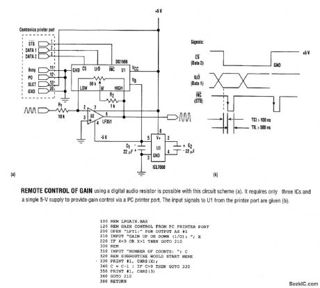
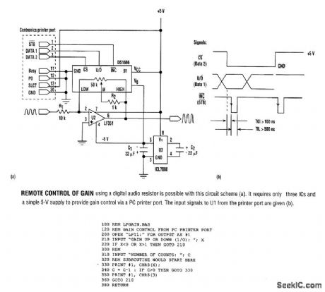
The listing is a test program that demonstrates circuit operation using an IBM-compatible PC. To form a subroutine for a main program, use lines 330 to 380, deleting line 360. The calling program then would pass values for X(wiper direction)and C(number of increments). (View)
View full Circuit Diagram | Comments | Reading(589)
Published:2009/6/23 3:10:00 Author:Jessie
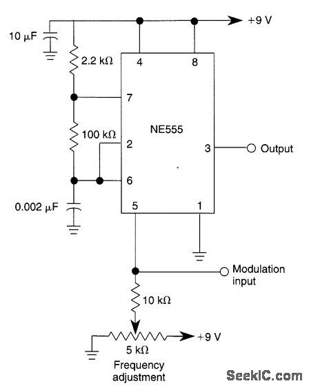
This circuit shows how to frequency-modutate the oscillator using a 555. Oscillator frequency is set with the 5-kΩ potentiometer and the modulation signal is dc-coupled. (View)
View full Circuit Diagram | Comments | Reading(1677)
Published:2011/7/28 2:14:00 Author:Ecco | Keyword: flashing switch , light intensity, 1.5KHZ
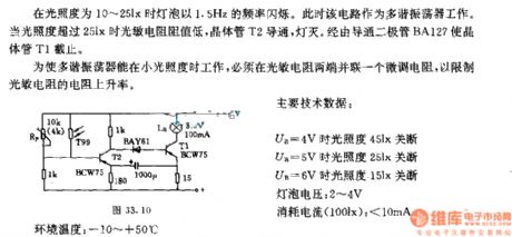
In the light degree of 13 ~ 25lx, the lamp flashes in the frequency of 1.5Hz. The circuits work as a multivibrator. When the light intensity is over 25lx, the value of photosensitive resistor is low, transistor T2 turns on, lights off. The diode BA127stops the transistor T1.
In order to make the multivibrator work in low illumination, it needs to connect a spinner resistor to thephotosensitive resistor in parallel to limit the increasingrate of theresistance of photosensitive.
The main technical data:
UB=4V, the light intensity is 45lx, it turns off;
UB=5V, the light intensity is 25lx, it turns off;
UB=6V, the light intensity is 15lx, it turns off;
The voltage of the lamp: 2~4V
The current consumption(100lx): <10mA
The environment temperature: -10~+50℃ (View)
View full Circuit Diagram | Comments | Reading(633)
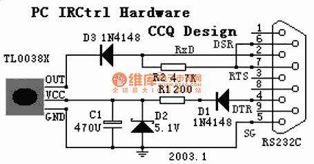
Published:2011/7/25 3:02:00 Author:Ecco | Keyword: PC , remote control
View full Circuit Diagram | Comments | Reading(729)
| Pages:174/312 At 20161162163164165166167168169170171172173174175176177178179180Under 20 |
Response in 12 hours
© 2008-2012 SeekIC.com Corp.All Rights Reserved.