
Index 179
Automatic dry hands circuit
Published:2011/5/5 23:04:00 Author:Jessie | Keyword: dry hands
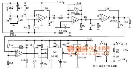
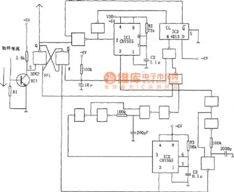
This circuit is consists of transimitting and infrared receiving control parts. Infrared transmit partproduces 5kHzfrequency by using 555 time-based circuit, drive infrared tubestransmit infrared light.When hand is under the dryer, because of infrared reflection action, PH302 will receive infrared and change it into electrical signals, by frequency selective amplifier which composed by IC1, IC2,IC3, it's output signal becomes DC signal into IC4 comparator after enlargement, plastic andfiltering. When the input level of IC4 isover 7V, its output changes into low level, trigger IC5 timer starts timing, pin 3 becomes high-level, 3DG130 connected, relay contacts suck close, connect resistance wire and fan.
(View)
View full Circuit Diagram | Comments | Reading(558)
Op amp common-mode voltage breakdown input stage and its protection measure circuit diagram
Published:2011/5/17 2:45:00 Author:Rebekka | Keyword: Op amp , common-mode voltage, breakdown input stage, protection measure
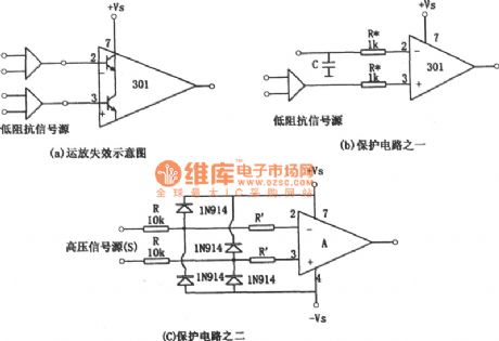
There is a current of the transistor collector junction flow from basal pole to collecting anode. If the source of resistance passes from feet 2 or feet ③ is low, then the collector junction current will be very large, and the input stage transistors will be damaged. In this case, remove the power supply voltage, and the signal source is not removed. The common-mode input will damage the ntegrated operational amplifier. Another case that makes the integrated operational amplifier common mode input failure is that the signal source has capacitive elements. The capacitance is charged to the high level of the signal source, remove the supply voltage and signal at the same time. Because the existance of charging voltage of the signal source capacitance, it is equivalent to the existance of signal source voltage. If the capacitor is greater than 0.1μF. The discharge current of the capacitor can burn the transistor. (View)
View full Circuit Diagram | Comments | Reading(975)
SINGLE_TONE_INFRARED_CONTROL_TRANSMITTER
Published:2009/6/19 4:07:00 Author:May
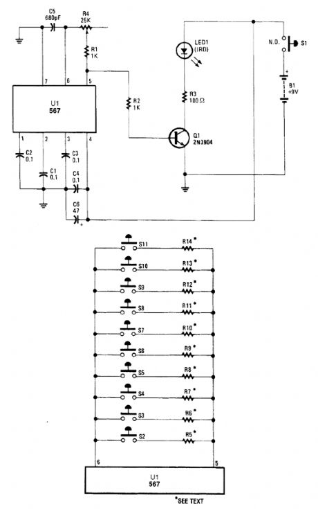
A modulated beam of IR light is produced by this transmitter. This circuit can be used for on/off controls or tone (CW) communications. The pot can be replaced by several pushbuttons and resis-tors, as shown for multitone applications. (View)
View full Circuit Diagram | Comments | Reading(516)
TV_REMOTE_CONTROL_RELAY
Published:2009/6/19 4:06:00 Author:May
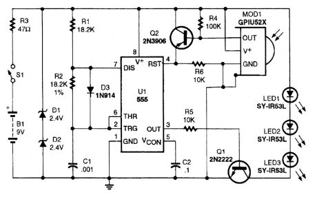
This circuit functions as an IR repeater to extend the range of your TV remote control. MOD1 is a P/N GP1U52X IR detector and the receiver is available as Radio Shack P/N 276-137. (View)
View full Circuit Diagram | Comments | Reading(2417)
Self-initiated control overcurrent protection circuit diagram
Published:2011/6/24 1:43:00 Author:Rebekka | Keyword: Self-initiated control , overcurrent protection
If the RS flip-flop reset still in the over-current condition, the level of FF1's Q-side is always high. It continues to cut off the device power supply. IC1 has been in the set state. The R side of FF1 does not work. The control circuit of the overcurrent devices can not only cut off the power and when it returns to be normal, it can start automatically. Thus the power interruption error which is generated by the phenomenon can be removed. (View)
View full Circuit Diagram | Comments | Reading(461)
Multi-purpose household protection circuit composed of the C036
Published:2011/6/24 3:23:00 Author:Rebekka | Keyword: Multi-purpose household protection
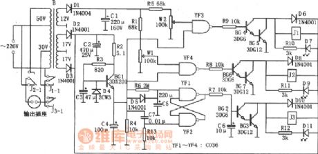
Delayed protection circuit is mainly composed of the charge and discharge loop (R6, C5), YF1 and the RS flip-flop, relay J3, driver circuit (BG2, BG3) composed of YF2. When it is connected with the power supply, because the voltage on C5 is not mutation, YF1 outputs low. It makes BG2, BG3 conducted, the relay J3 will be pulled in. The load starts to work because the J3-1 is connected to the power supply. (View)
View full Circuit Diagram | Comments | Reading(583)
SOLDERING_IRON_CONTROL
Published:2009/6/19 3:28:00 Author:May
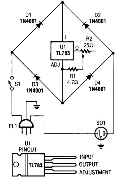
A current control to temperature regulate a soldering iron uses a high-voltage integrated reg-ulator, TL783 (U1). Wlth the component values specified, the circuit should be used with a sol-dering iron of 25 W or less. (View)
View full Circuit Diagram | Comments | Reading(2508)
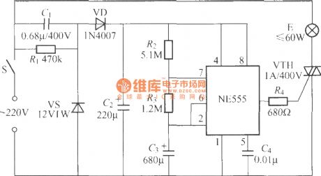
Breeze ceiling fan temperature controller circuit composed of the NE555
Published:2011/6/28 3:16:00 Author:Rebekka | Keyword: Breeze ceiling fan, temperature controller
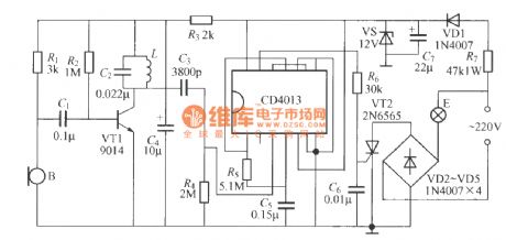
When environment temperature increases, the resistance of the corresponding R7 R6 become smaller and make the IC (2) feet down to less than a third potential VDD and it is reset, 3 feet output high level. So the controlled silicon AC zero-voltage switching composed of D2~D5、SCR、BG1、BG2 will be turned on. Fan D operates when supply power is open; When the environment temperature falls, resistance of the corresponding R7, R6 changes, 555 is reset because the feet (2) is larger than a third potential VDD, (3) feet outputs low level, so that the controlled silicon AC zero-voltage switching is closed. The electric fan D stops because the power supply is closed. (View)
View full Circuit Diagram | Comments | Reading(947)
BACKUP_BATTERY_MONITOR_CHARGER_ALARM
Published:2009/6/19 2:59:00 Author:May


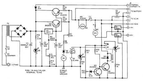
Battery Condition Meter Calibratio Lead-Acid Battery Lead Calcium RatteryColor Voltage Color VoltageRed 11.6 and below Red 11.6 and belowYellow 11.6 to 12.0 Yellow 11.6 to 12.0Green 12.0 to 13.8 Green 12.0 to 13.5Red 13.5 and higher Red 13.5 and higher
Charging voltage is constant at the normal full-charge level, so the charging current drops as full oharge is approached, and full charge is maintained with a trickle current. The charging voltage can be adjusted between approximately 10 and 15 Vdc to accommodate lead-acid (13.8 V) or lead-cal-ciurn (13.2V, 13.5V maximum) deep-cycle storage batteries.A separate connection is provided so that an extemal charger can be used when greater than 3 A is needed to charge a pa'rtially discharged battery. Intemal circuitry will maintain the charging volt-age to the battery at the nominal full-charge voltage level, regardless of the voltage supplied by the external charger, which will be 2V or more greater than that applied by the regulator to the storage battery. Warning: do not fast-charge deep-cycle storage batteries!A pair of meters calibrated to indicate 20 Vdc and 20 Adc full-scale monitor voltage and current when battery power is used.A separate, suppressed zero, expanded-scale meter calibrated over the range of about 10 to 15 Vdc allows immediate and constant indication of the state of charge of the station's backup battery.This meter scale is calibrated in bands of red, yellow, and green, as explained in the table. The nar-row yellow segment is based on the assurnption that solid-state transceivers might not operate prop-erly below +12 Vdc. The intemal power supply is used to calibrate this meter. A DMM should be used for greatest accuracy.An alarm circuit is included to indicate when the battery has been discharged by 60 percent tothe 11.6-Vdc level When battery voltage IS above 11.6 V, the green LED will be illuminated;when voltage falls to 11.6V, the green LED goes out and the red LED lights A piezo audible alarm soundsat this low voltage level unless silenced by the toggle switch controlling it.A pair offixed three-terminal regulators are included to provide+9 and+6 Vdc (View)
View full Circuit Diagram | Comments | Reading(1643)
BATTERY_CHARGER_CONTROLLER
Published:2009/6/19 2:47:00 Author:May
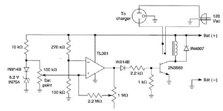
When the battery voltage is low, the TL081 comparator produces a high output, tuming on the 2N3569 relay driver. As the battery voltage approaches the set point, the relay driver is cut off, open-ing the 120-Vac supply. (View)
View full Circuit Diagram | Comments | Reading(2020)
The subsonic remote control lamp switch circuit (2)
Published:2011/7/5 1:28:00 Author:zj | Keyword: The subsonic, remote control, lamp switch circuit
As shown in the figure ultrasonic remote control lamp switch circuit uses digital integrated circuit, which is composed of acoustic wave transducer, amplifier and general digital integrated circuit. In the graph, L is a 2.2mH inductance; 18kHz subsonic generator adopts a rubber ball puffer type ultrasonic horn. The acoustic transducer B can use CRZ2-113F ordinary electret capacitor microphone. (View)
View full Circuit Diagram | Comments | Reading(1070)
The subsonic remote control lamp switch circuit (1)
Published:2011/7/5 1:49:00 Author:zj | Keyword: The subsonic, remote control, lamp switch circuit
As shown, the remote control light uses 18kHz acoustic wave as remote control signal. The auditory range is from 20Hz to 20kHz. Ear inaudible ultrasonic is more than 20kHz. Although 18kHz wave is in audible sound wave range, it is in the audible sound wave end edge and is close to the lowest frequency. And human ear will not be sensitive. You can only hear the sound Ci Ci . So we call it The ultrasonic. (View)
View full Circuit Diagram | Comments | Reading(449)
Delay light pull switch circuit (3)
Published:2011/7/5 1:52:00 Author:zj | Keyword: Delay light, pull switch circuit
View full Circuit Diagram | Comments | Reading(429)
Cycle timing lamp circuit
Published:2011/7/5 3:39:00 Author:zj | Keyword: Cycle timing, lamp circuit
As the diagram shows it is a cycle timing lamp circuit. When the switch S is closed, the lamp will automatically light up for 50min and go out for 10min,and this process will go round and begin again and again. It can be used as reading and writing desktop lamp. It can force the student to relax for 10min after working for 50min. It is good for students' health. (View)
View full Circuit Diagram | Comments | Reading(513)
Four path lights with bird control circuit using BH9201
Published:2011/7/5 22:46:00 Author:zj | Keyword: Four path lights, bird twitter control circuit
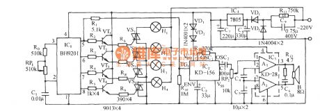
The circuit is shown above. It is composed of a lamp control circuit of SCR trigger control circuit, a sounding circuit, audio power amplifier circuit of birdsong and AC voltage reducing rectifier circuit. It can in the four path lights string strobe at the same time, a beautiful melodious birds toot cries. BH9201 is a special lantern control integrated circuit, it has four control signal output regulator connected in an external pins 2, 3 of RP1, can make the four path lights show jumping, running water, the light, the three state. R0, RP1, C1 inside the BH9201 oscillation circuit of an external resistor and capacitor. (View)
View full Circuit Diagram | Comments | Reading(633)
DUAL_CONTROL_HEXFET_SWITCH
Published:2009/6/19 2:33:00 Author:May
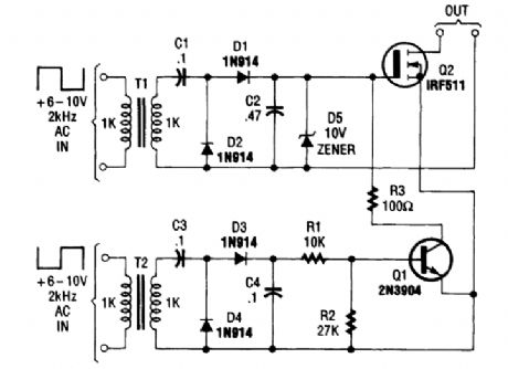
This dual-control switch uses two 6 to 10-Vac sources to trigger the circuit on and off; one source for each function. (View)
View full Circuit Diagram | Comments | Reading(546)
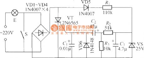
Small non-contact refrigerator time delay protector circuit diagram
Published:2011/5/15 6:03:00 Author:Rebekka | Keyword: Small non-contact refrigerator, time delay protector
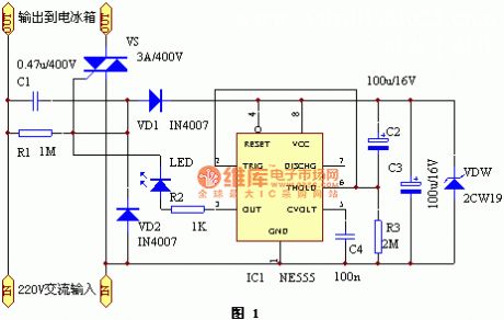
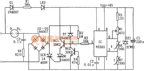
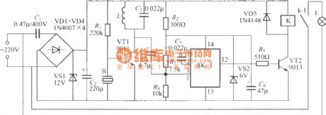
The protector circuit is shown in the figure 1. 220V AC power passes the capacitor C1 buck, VD1 half-wave rectifier to the regulated VDW the time base circuit 555 as a working power supply. When it connects to power supply for about 5 minutes, the time base circuit ③ foot outputs from low to a high level. The two-way thyristor VS will be conducted to work and provides power supply for the refrigerator. At this time the light-emitting diode LED is lit. It indicates the power supply is normal. (View)
View full Circuit Diagram | Comments | Reading(2453)
REMOTE_TWO_WAY_ac_SWITCH_HOOkUP
Published:2009/6/19 2:28:00 Author:May
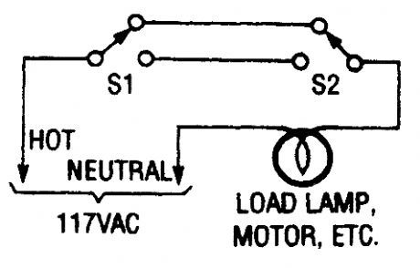
This switching arrangement is the type of arrangement used in both domestic and industrial environments to allow a light or other ac-operated device to be controlled from more than one location (View)
View full Circuit Diagram | Comments | Reading(518)
dc_CONTROLLED_FET_SWITCH
Published:2009/6/19 2:28:00 Author:May
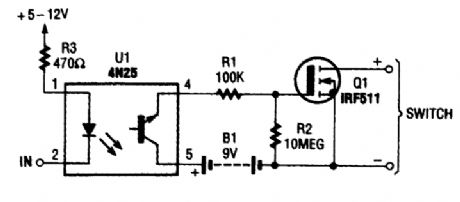
This dc-controlled switch uses an optoisolator/coupler, U1, to electrically isolate the input signal from the output-control device. (View)
View full Circuit Diagram | Comments | Reading(1394)
HEXFET_SWITCH
Published:2009/6/19 2:27:00 Author:May
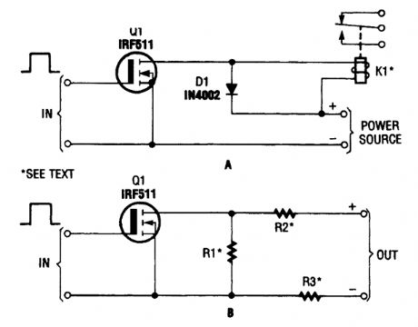
The hexFET can switch dc power to relays (as shown in A), motors, lamps, and numerous other devices. That arrangement can even be used to switch resistors in and out of a circuit, as shown in B. R1, R2, and R3 represent resistive loads that can be switched in and out of the circuit. (View)
View full Circuit Diagram | Comments | Reading(976)
| Pages:179/312 At 20161162163164165166167168169170171172173174175176177178179180Under 20 |
Circuit Categories
power supply circuit
Amplifier Circuit
Basic Circuit
LED and Light Circuit
Sensor Circuit
Signal Processing
Electrical Equipment Circuit
Control Circuit
Remote Control Circuit
A/D-D/A Converter Circuit
Audio Circuit
Measuring and Test Circuit
Communication Circuit
Computer-Related Circuit
555 Circuit
Automotive Circuit
Repairing Circuit