
Control Circuit
Index 21
Touch Alarm System
Published:2013/3/25 4:25:00 Author:Ecco | Keyword: Touch Alarm System
Touch Alarm circuit is widely used for security, which is installed on the door. The advantages of this alarm is because the cost is cheap and difficult to detect by burglars / intruders.
(View)
View full Circuit Diagram | Comments | Reading(1798)
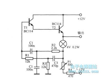
Easy Build Motorcycle Alarm
Published:2013/3/25 4:16:00 Author:Ecco | Keyword: Easy Build Motorcycle, Alarm
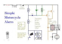
The following circuit is a simple, cheap and easy build motorcycle alarm. The circuit just required 2 transistors to drive the relay the the relay act as a switch to activate the buzzer. Any number of normally-open switches may possibly be applied.
(View)
View full Circuit Diagram | Comments | Reading(1466)
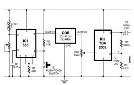
Electronic Siren based NE555
Published:2013/3/25 4:04:00 Author:Ecco | Keyword: Electronic Siren
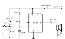
Here the circuit diagram of electronic siren based NE555. This circuit produces a sound like factory siren. It applies a 555 timer IC which is utilized as an astable multivibrator of a center frequency of about 300Hz. The frequency is controlled by the pin 5 of the IC.
(View)
View full Circuit Diagram | Comments | Reading(1552)
Adjustable Analog Timer
Published:2013/3/25 4:02:00 Author:Ecco | Keyword: Adjustable Analog Timer
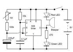
This is a very simple adjustable analog timer circuit diagram. You can build this circuit just for fun, for newbie project or may be…, this circuit could be used to set a time limit when playing games or as an egg-timer in the kitchen.
(View)
View full Circuit Diagram | Comments | Reading(2409)
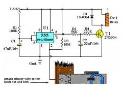
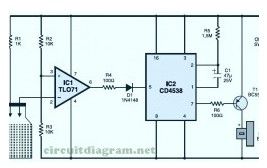
Pyroelectric Fire Alarm System
Published:2013/3/25 4:02:00 Author:Ecco | Keyword: Pyroelectric , Fire Alarm System

This is definitely an ultra-sensitive fire sensor that exploits the direct piezoelectric property of an ordinary piezo component to recognize the fire. The lead zirconate titanate crystals within the piezo component have the property to deform and produce an electrical potential when heated, thus converting the piezo component into a heat sensor.
(View)
View full Circuit Diagram | Comments | Reading(1287)
Multitone Siren Alarm
Published:2013/3/25 4:01:00 Author:Ecco | Keyword: Multitone Siren Alarm
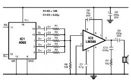
Here the simple schematic of multitone siren alarm circuit. This multitone siren is effective for reverse horns, burlgar alarms, and many others. It generates five various audio tones and is much more earcatching than a single-tone siren.
(View)
View full Circuit Diagram | Comments | Reading(1539)
Fire Alarm with LDR Sensor
Published:2013/3/25 3:48:00 Author:Ecco | Keyword: Fire Alarm , LDR Sensor
This is the fire alarm circuit which use LDR to sense the smoke from the fire, so it can be used to detect any dark smoke. With the onset of summer season, possibilities of fire accidents go up. These fire accidents could be prevented if timely alarms are available. The circuit given right here alerts the user against these fire accidents.
(View)
View full Circuit Diagram | Comments | Reading(1482)
Cheap Motorcycle Alarm
Published:2013/3/25 3:47:00 Author:Ecco | Keyword: Cheap Motorcycle Alarm

This is simple to build and cheap motorcycle alarm circuit which could be fitted in motorcycles to take care of them from getting stolen. The tiny circuit may be hidden anyplace, without having any difficult wiring. Practically, it fits all motorcycles as long as they’ve a electric battery.
(View)
View full Circuit Diagram | Comments | Reading(1331)
Power Supply Failure Alarm
Published:2013/3/25 3:44:00 Author:Ecco | Keyword: Power Supply, Failure Alarm

This is the ‘special’ circuit design of power supply failure alarm. The vast majority of the power supply failure alarm / indicator circuits require a independent power supply for themselves. However the alarm circuit introduced right here requires no extra supply power source.
(View)
View full Circuit Diagram | Comments | Reading(1193)
Notebook Anti Theft Protector
Published:2013/3/25 3:43:00 Author:Ecco | Keyword: Notebook, Anti Theft Protector
Here the notebook anti theft protector circuit to secure your important netbook / notebook from stealing. Basically, this is a mini security alarm generator. Fixed inside the notebook case, it will definitely sound a noisy alarm when a person attempts to grab the notebook. This very sensitive circuit utilizes a homemade tilt switch to turn on the alarm system through tilting of the laptop computer case.
(View)
View full Circuit Diagram | Comments | Reading(1146)
Logic overvoltage protection
Published:2013/3/20 1:56:00 Author:Ecco | Keyword: Logic overvoltage protection

Zener diode ZD1 senses the power supply voltage, and if the supply voltage rise above 6 V, Q1 will-turn on. Therefore, Q2 conducts short the rail. Next events depend on the source supply. It will either shut down, go into current-limit or blow its supply fuse. None of these will damage the TTL chips. The rating of Q2 depends on the source supply, and whether it will be required to operate continuously in the event of failure. Its current rating has to be in excess of the source supply.
(View)
View full Circuit Diagram | Comments | Reading(1431)
RC control circuit
Published:2013/3/12 3:30:00 Author:Ecco | Keyword: RC control
RC control circuit is shown as figure.
(View)
View full Circuit Diagram | Comments | Reading(1055)
PWM Motor/Light Controller
Published:2013/3/10 22:26:00 Author:Ecco | Keyword: PWM Motor, Light Controller
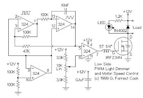
These two schematics are variations on another PWM circuit that I designed. The diagrams are for 12V operation only and there are high side (common ground) and low side (common +12V) versions. The low side version of the circuit uses an N Channel FET, the high side version of the circuit uses a P Channel FET. N Channel devices tend to handle more current than P Channel devices, they are also less expensive. The high side version of the circuit is useful when one side of the load has to be grounded.
This circuit can switch a fairly high amount of current, an IRFZ34N MOSFET can handle over 35 Amps if connected to a proper heat sink. Higher power FETs, such as the IRFZ48N or IRF1010Z can be substituted if even larger currents are required. It is also possible to connect multiple FETs in parallel for even more current capacity. Always use thermally conductive grease between the FET and the heat sink, and remember that the heat sink is electrically live.
Inductive loads (motors) may require special care since they can generate large voltage spikes that can damage the MOSFET. Replacing the 1N4002 with a fast recovery diode may help absorb the reverse voltage kick when driving an inductive load such as a motor. If you use these circuits for experiments with electric vehicles, be sure to install a circuit breaker in series with the battery, the circuit breaker should be easy to reach by the driver. This is especially important due to the fact that when MOSFETs fail, they often short out, leaving the motor on at full speed.
Note that the pwm control has an opposite effect on these two circuits, the low side version is on with a high pin 7 output voltage and the high side version is on with a low output.
The inductor on the gate side of the power MOSFET transistor can be a ferrite bead or a few turns of wire wrapped around a 10 ohm, 1/4W resistor. The purpose of this part is to prevent RF oscillations from occurring in the MOSFET circuitry.
(View)
View full Circuit Diagram | Comments | Reading(1699)
PWM Motor Speed Controller / DC Light Dimmer
Published:2013/3/10 22:25:00 Author:Ecco | Keyword: PWM Motor, Speed Controller , DC Light Dimmer
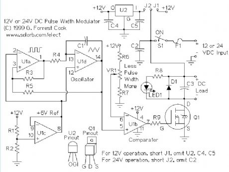
A pulse width modulator (PWM) is a device that may be used as an efficient light dimmer or DC motor speed controller. The circuit described here is for a general purpose device that can control DC devices which draw up to a few amps of current. The circuit may be used in either 12 or 24 Volt systems with only a few minor wiring changes. This device has been used to control the brightness of an automotive tail lamp and as a motor speed control for small DC fans of the type used in computer power supplies.
A PWM circuit works by making a square wave with a variable on-to-off ratio, the average on time may be varied from 0 to 100 percent. In this manner, a variable amount of power is transferred to the load. The main advantage of a PWM circuit over a resistive power controller is the efficiency, at a 50% level, the PWM will use about 50% of full power, almost all of which is transferred to the load, a resistive controller at 50% load power would consume about 71% of full power, 50% of the power goes to the load and the other 21% is wasted heating the series resistor. Load efficiency is almost always a critical factor in solar powered and other alternative energy systems.
One additional advantage of pulse width modulation is that the pulses reach the full supply voltage and will produce more torque in a motor by being able to overcome the internal motor resistances more easily. Finally, in a PWM circuit, common small potentiometers may be used to control a wide variety of loads whereas large and expensive high power variable resistors are needed for resistive controllers.
The main Disadvantages of PWM circuits are the added complexity and the possibility of generating radio frequency interference (RFI). RFI may be minimized by locating the controller near the load, using short leads, and in some cases, using additional filtering on the power supply leads. This circuit has some RFI bypassing and produced minimal interference with an AM radio that was located under a foot away. If additional filtering is needed, a car radio line choke may be placed in series with the DC power input, be sure not to exceed the current rating of the choke. The majority of the RFI will come from the high current path involving the power source, the load, and the switching FET, Q1.
(View)
View full Circuit Diagram | Comments | Reading(4448)
PWM DC Motor Speed Control
Published:2013/3/10 22:23:00 Author:Ecco | Keyword: PWM, DC Motor , Speed Control
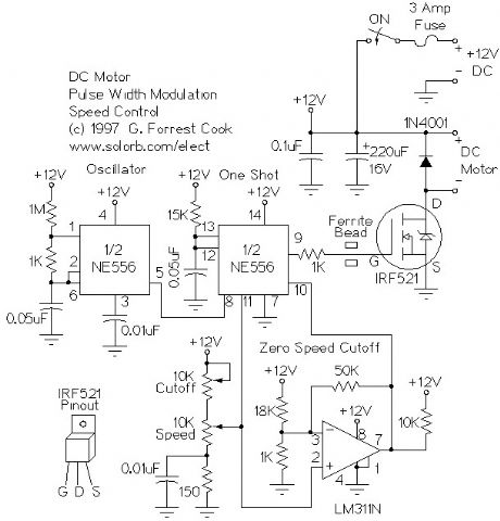
The left half of the 556 dual timer IC is used as a fixed frequency square wave oscillator. The oscillator signal is fed into the right half of the 556 which is configured as a variable pulse width one-shot monostable multivibrator (pulse stretcher). The output of the one-shot is a variable width square wave pulse, the pulse width is set with the speed control pot on the control voltage input. The variable width output pulse switches the IRF521 MOSFET transistor on and off. The MOSFET amplifies the current of this signal so that it is powerful enough to control a small DC motor. The 311 comparator is used to cut off the one-shot via the reset pin when the control voltage is below a certain threshold, the 311 is also controlled by the speed control pot. The cut off circuit is necessary because the 556 one-shot circuit will always put out a small pulse, even when the control voltage is at zero.
(View)
View full Circuit Diagram | Comments | Reading(2722)
All-Ears QSK Timing Generator
Published:2013/3/7 3:10:00 Author:Ecco | Keyword: All-Ears, QSK, Timing Generator

In the world of amateur (ham) radio morse code communications, QSK refers to a method of operation where the transmitter and receiver are alternately active when the key is down or up. QSK is also known as break-in keying. QSK operation allows the operator to hear what is happening on their frequency in the brief times between transmitting morse code dits and dahs. The conversation can be quickly interrupted by the other station, or by a third station. The sender also knows immediately if their signal is being interfered with.
The design of a QSK-capable radio station is somewhat tricky. A QSK system has to quickly switch the antenna between the transmitter and receiver, key the transmitter, mute the receiver during transmission and disable the transmitter's oscillator during receiving. It is also desirable to change the receiver's AGC response time from fast to slow when not transmitting. By adding small delays at the beginning and ending of the dots and dashes, it is possible to generate signals with slightly longer and shorter lengths compared the original morse code. These modified signals sequence the entire system in order to eliminate transmitted chirps, T/R relay arcing and receiver clicking.
Here's a typical sequence for sending one morse code dit , items in parentheses happen simultaneously: (key down, T/R relay to transmit, transmitter oscillator on, receiver mute), delay, transmitter output on for duration of dit, (key up, transmitter output off), delay, (T/R relay to receive, transmitter oscillator off, receiver unmute) Additionally, the receiver AGC slow/fast signal needs to go to fast at the beginning the the first key down event, and should switch to fast a few seconds after the last key up event.
This circuit takes a TTL-level keying signal and produces three TTL-level output signals, and inverted versions of the three signals. This combination of outputs is useful for driving a variety of control circuits that can interface to the transmitter and receiver. The timing generator also generates the necessary signals for automatic non-QSK transmit/receive switching.
(View)
View full Circuit Diagram | Comments | Reading(1835)
Solar Panel Charge Controller / Low Voltage Disconnect Circuit (SPC1)
Published:2013/3/6 3:14:00 Author:Ecco | Keyword: Solar Panel, Charge Controller , Low Voltage Disconnect

This Solar Power Center design appeared as a pair of articles in Home Power Magazine.
The charge controller is used to connect a solar panel to a 12 volt lead acid battery, it regulates the charging of the battery and allows the battery to be charged up to a preset voltage. This prevents the battery from over-charging and boiling off electrolyte.
The low voltage disconnect is used to connect a load to the same 12 volt lead acid battery, the LVD acts as a smart switch, it auto disconnects the load if the battery voltage falls below a set point.
When used together, these circuits keep the battery operating within normal voltage limits which greatly extends the life of the battery. The circuit board was designed to be split into two independent circuits, that is why there are two connections to the battery.
(View)
View full Circuit Diagram | Comments | Reading(6152)
SCC2 10 Amp Solar Charge Controller
Published:2013/3/6 3:13:00 Author:Ecco | Keyword: 10 Amp , Solar Charge Controller
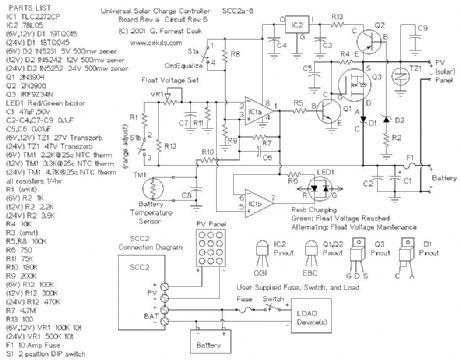
The SCC2 is a solar charge controller, its function is to regulate the power flowing from a photovoltaic panel into a rechargeable battery. It features easy setup with one potentiometer for the float voltage adjustment, an equalize function for periodic overcharging, and automatic temperature compensation for better charging over a range of temperatures.
The goal of the circuit design was to make a charge controller with analog simplicity, high efficiency, and reliability. A medium power solar system can be built with a 12V solar panel up to 10 amps, the SCC2, and a rechargeable battery. The SCC2 works with lead acid, NiCD and NiMH batteries with ratings from less than one to several hundred amp-hours. With the appropriate parts selection, the SCC2 can be operated at 6V, 12V, 24V or other voltages.
(View)
View full Circuit Diagram | Comments | Reading(4505)
Analog Shunt-mode 12V 500mA Solar Charge Controller
Published:2013/3/6 3:11:00 Author:Ecco | Keyword: Analog, Shunt-mode , 12V, 500mA, Solar Charge Controller
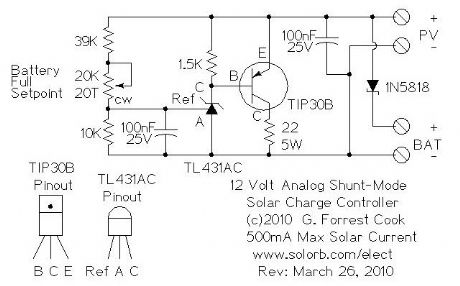
This circuit is an analog alternative to the switching Shunt-mode Solar/Wind Charge Controller. It is one of the simplest ways to regulate the solar charging of a rechargeable battery, using about a dozen parts. Despite its simplicity, the circuit is relatively efficient. Unlike the all-or-nothing switching shunt-mode controller, this circuit gradually diverts solar power from the battery to the dump load resistor as the battery reaches the preset battery float voltage. As shown, the circuit is limited to 500mA of solar charging current. Higher power systems will be better served with a series switching charge controller.
The circuit shown is set up to charge a 12V battery, it can be modified to support both lower and higher voltage battery systems by changing the value of the 39K resistor.
(View)
View full Circuit Diagram | Comments | Reading(4149)
Shunt-mode Solar/Wind Charge Controller
Published:2013/3/6 3:10:00 Author:Ecco | Keyword: Shunt-mode , Solar, Wind , Charge Controller
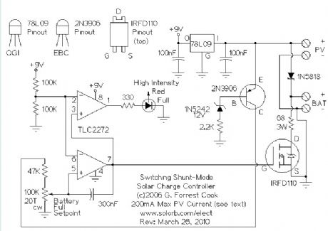
When connecting a solar panel to a rechargeable battery, it is important to use a charge controller circuit to prevent the battery from overcharging. Charge control can be performed with a number of different circuit types. Low-power solar systems can use a series analog charge controller (voltage regulator), an example is shown as the upper part of this circuit. Higher power systems can use a series switching charge controller, such as my SCC3 design. Very large systems, such as grid-tied installations, often use a maximum power-point (MPPT) charge controller. This shunt-mode circuit is best suited for low-power systems, it is more efficient than charge controllers based on series-mode voltage regulators.
Series regulators (both analog and switching) control battery charging by interrupting the flow of current from the solar panel to the battery when the battery reaches a preset full voltage. MPPT controllers use controllable switching regulator circuits to convert PV power to high voltage and back down to lower voltages, they are complicated and require a bit of power to operate, but offer excellent efficiency on high power systems.
This circuit is for a switching shunt-mode charge controller. In a shunt-mode circuit, the solar panel is connected directly to the battery via a series diode. The diode prevents battery current from flowing back through the PV panel at night. When the solar panel charges the battery up to the desired full voltage, the shunt circuit connects a resistive load across the battery in order to absorb the excess PV charging current. An alternate but similar approach to this switching shunt-mode PV regulator is the Analog Shunt-Mode circuit.
(View)
View full Circuit Diagram | Comments | Reading(7709)
| Pages:21/312 At 202122232425262728293031323334353637383940Under 20 |
Circuit Categories
power supply circuit
Amplifier Circuit
Basic Circuit
LED and Light Circuit
Sensor Circuit
Signal Processing
Electrical Equipment Circuit
Control Circuit
Remote Control Circuit
A/D-D/A Converter Circuit
Audio Circuit
Measuring and Test Circuit
Communication Circuit
Computer-Related Circuit
555 Circuit
Automotive Circuit
Repairing Circuit