
Control Circuit
Index 22
60 Amp Modification for the SCC3 12 Volt Solar Charge Controller
Published:2013/3/6 3:08:00 Author:Ecco | Keyword: 60 Amp, Modification , 12 Volt, Solar Charge Controller
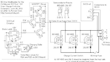
This article describes modifications that can be made to the 12V, 20 Amp SCC3 solar charge controller to allow operation at up to 60 Amps. Similar modifications can be performed to achieve a maximum operating current of 40 Amps (2 sets of IRF4905 MOSFETs and 20L15T diodes) or 80 Amps (4 sets of IRF4905 MOSFETs and 20L15T diodes). This article describes the modification for 60 Amps.
(View)
View full Circuit Diagram | Comments | Reading(6115)
BVM1 - 12 Volt Battery Voltage Monitor
Published:2013/3/6 2:56:00 Author:Ecco | Keyword: 12 Volt, Battery Voltage Monitor
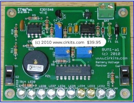
The BVM1 is an ultra low power ten LED battery voltmeter circuit that is optimized for monitoring solar-charged 12V battery systems. The circuit features an expanded meter scale that displays ten color-coded voltage steps from 10.5V to 15.0V. Power is conserved by only turning on the appropriate LED for a short but bright flash once every 1.25 seconds. The LED display can be turned on continuously (no blinking) by turning the Calibrate switch on, more battery power is consumed in this mode.
The BVM1 also includes a battery low voltage beeper that warns when the battery voltage drops below a preset voltage. The beeper can be turned on and off with the L.V. Beep Activate switch.
The BVM1 is protected against reverse voltage connection and is fused for safety. (View)
View full Circuit Diagram | Comments | Reading(1997)
SPC3 9 Amp in / 10 Amp out Solar Power Center
Published:2013/3/6 2:49:00 Author:Ecco | Keyword: 9 Amp , 10 Amp, out, Solar Power Center
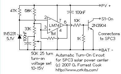
The SPC3 is a solar power center, it can handle all of the power functions for a solar charged 12 Volt DC system. The SPC3 contains a 9 amp photovoltaic charge controller, a 10 amp low voltage load disconnect circuit and a pair of built-in white LEDs for area illumination. The low voltage disconnect circuit has a load on-off switch, and a battery low voltage indicator. By using the SPC3 as the center of a solar powered device, long battery life is assured. The SPC3 can be used for a self-contained solar lighting system, it can be used for making solar powered audio and radio devices and much more.
(View)
View full Circuit Diagram | Comments | Reading(1918)
SCC3 - 12 Volt 20 Amp Solar Charge Controller
Published:2013/3/6 2:47:00 Author:Ecco | Keyword: 12 Volt , 20 Amp, Solar Charge Controller
The SCC3 is a solar charge controller, its function is to regulate the power flowing from a photovoltaic panel into a rechargeable battery. It features easy setup with one potentiometer for the float voltage adjustment and an equalize function for periodic overcharging. Automatic temperature compensation optimizes battery charging over a wide range of temperatures. The SCC3 is able to handle reverse polarity connection of both the battery and photovoltaic panel.
The design goals of this circuit were efficiency, simplicity, reliability and the use of field replaceable parts. The circuit has been designed to be radio-quiet, which makes it suitable for ham radio applications. A medium power solar system can be built with the SCC3, a 12V (nominal) solar panel that is rated up to 20 amps, and a lead acid or other rechargeable battery that is rated from 500 milliamp hours to 400 amp hours of capacity.
(View)
View full Circuit Diagram | Comments | Reading(1495)
TV REMOTE CONTROL JAMMER Circuit
Published:2013/3/5 21:00:00 Author:Ecco | Keyword: TV , REMOTE CONTROL , JAMMER
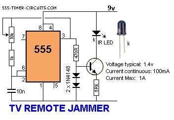
This circuit confuses the infra-red receiver in a TV. It produces a constant signal that interferes with the signal from a remote control and prevents the TV detecting a channel-change or any other command. This allows you to watch your own program without anyone changing the channel !! The circuit is adjusted to produce a 38kHz signal. The IR diode is called an Infra-red transmitting Diode or IR emitter diode to distinguish it from a receiving diode, called an IR receiver or IR receiving diode. (A Photo diode is a receiving diode). There are so many IR emitters that we cannot put a generic number on the circuit to represent the type of diode. Some types include: CY85G, LD271, CQY37N (45?, INF3850, INF3880, INF3940 (30?. The current through the IR LED is limited to 100mA by the inclusion of the two 1N4148 diodes, as these form a constant-current arrangement when combined with the transistor and 5R6 resistor.
(View)
View full Circuit Diagram | Comments | Reading(1363)
STEPPER MOTOR CONTROLLER TE555-1 Circuit
Published:2013/3/5 20:50:00 Author:Ecco | Keyword: STEPPER MOTOR , CONTROLLER
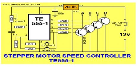

The direction of rotation is determined by the FORWARD and REVERSE switches and the motor does not take any current when a switch is not pressed.
(View)
View full Circuit Diagram | Comments | Reading(5815)
SERVO TESTER Circuit
Published:2013/3/5 20:45:00 Author:Ecco | Keyword: SERVO TESTER
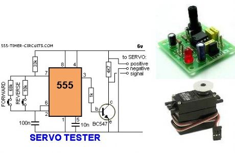
This circuit can be used to manually turn a servo clockwise and anti-clockwise. By pushing the forward or reverse button for a short period of time you can control the rotation of the servo. It will also test a servo. Here is a photo of a kit from Cana Kit for $10.00 plus postage (it is a slightly different circuit) and a motor and gearbox, commonly called a servo. The output shaft has a disk or wheel containing holes. A linkage or push-rod is fitted to a hole and when the disk rotates, the shaft is pushed and pulled. The shaft only rotates about 180?to actuate flaps or ailerons etc.
(View)
View full Circuit Diagram | Comments | Reading(6719)
RAIN ALARM Circuit
Published:2013/3/5 20:39:00 Author:Ecco | Keyword: RAIN ALARM
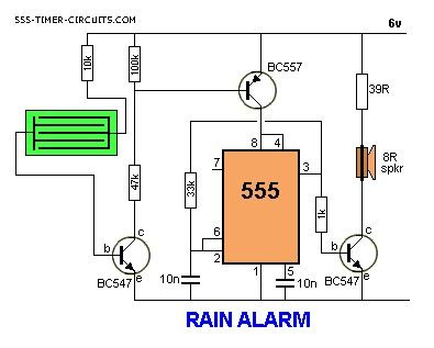
This circuit consumes no current until moisture is detected on the rain plate.
(View)
View full Circuit Diagram | Comments | Reading(2222)
DUMMY ALARM Circuit
Published:2013/3/4 21:48:00 Author:Ecco | Keyword: DUMMY ALARM
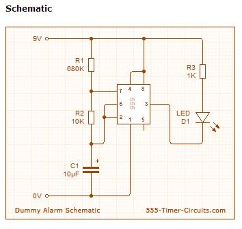
This Dummy Alarm project makes an LED flash briefly once every 5 seconds to imitate the indicator light of a real alarm. Overview The circuit is designed to use very little current to prolong battery life so that it can be left on permanently. An on/off switch is not included, but could be added if you wish. The 7555 timer IC used is a low power version of the standard 555 timer. A 憇uperbright?red LED is used because this provides a bright flash with a low current. The LED is off for most of the time so the average total current for the circuit is less than 0.2mA. With this very low current a set of 3 alkaline AA cells should last for several months, maybe as long as a year.
(View)
View full Circuit Diagram | Comments | Reading(1412)
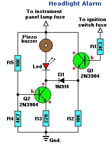
Headlight Alarm
Published:2013/2/27 20:59:00 Author:muriel | Keyword: Headlight Alarm
View full Circuit Diagram | Comments | Reading(2212)
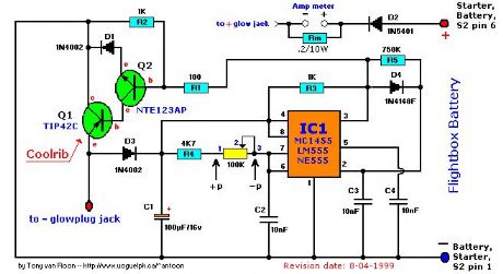
Glowplug Driver (a)
Published:2013/2/27 20:57:00 Author:muriel | Keyword: Glowplug Driver (a)
View full Circuit Diagram | Comments | Reading(957)
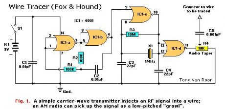
Fox & Hound, wire tracer
Published:2013/2/27 20:56:00 Author:muriel | Keyword: Fox & Hound, wire tracer
View full Circuit Diagram | Comments | Reading(2548)
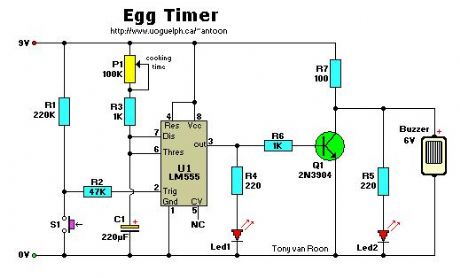
Egg Timer
Published:2013/2/27 20:53:00 Author:muriel | Keyword: Egg Timer
View full Circuit Diagram | Comments | Reading(1290)
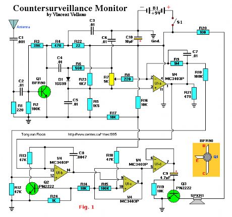
Countersurveillance Monitor
Published:2013/2/27 20:44:00 Author:muriel | Keyword: Countersurveillance Monitor
View full Circuit Diagram | Comments | Reading(817)
Car Back-up Alarm
Published:2013/2/27 20:37:00 Author:muriel | Keyword: Car Back-up Alarm

View full Circuit Diagram | Comments | Reading(784)
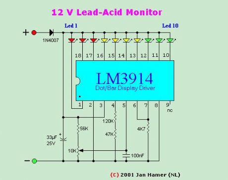
Battery Monitor for 12V Lead-Acid
Published:2013/2/27 20:27:00 Author:muriel | Keyword: Battery Monitor , 12V Lead-Acid
View full Circuit Diagram | Comments | Reading(2003)
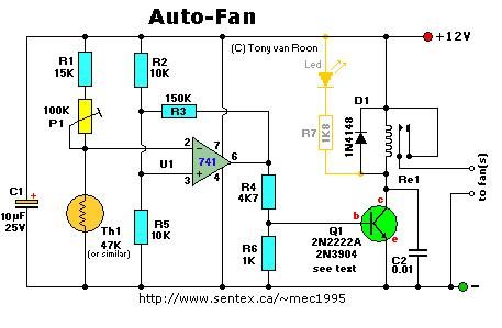
Auto-Fan, temperature control
Published:2013/2/27 20:23:00 Author:muriel | Keyword: Auto-Fan, temperature control
View full Circuit Diagram | Comments | Reading(1207)
Alternating On-Off Switch, #2
Published:2013/2/27 20:17:00 Author:muriel | Keyword: Alternating On-Off Switch
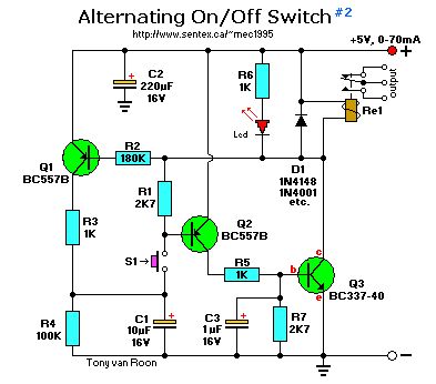
View full Circuit Diagram | Comments | Reading(2005)
Alternating On-Off Switch, #1
Published:2013/2/27 20:16:00 Author:muriel | Keyword: Alternating On-Off Switch
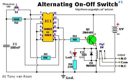
View full Circuit Diagram | Comments | Reading(1259)
A Simple Field Strength Indicator
Published:2013/2/25 20:19:00 Author:muriel | Keyword: Field Strength Indicator
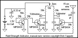
View full Circuit Diagram | Comments | Reading(874)
| Pages:22/312 At 202122232425262728293031323334353637383940Under 20 |
Circuit Categories
power supply circuit
Amplifier Circuit
Basic Circuit
LED and Light Circuit
Sensor Circuit
Signal Processing
Electrical Equipment Circuit
Control Circuit
Remote Control Circuit
A/D-D/A Converter Circuit
Audio Circuit
Measuring and Test Circuit
Communication Circuit
Computer-Related Circuit
555 Circuit
Automotive Circuit
Repairing Circuit