
Control Circuit
Index 23
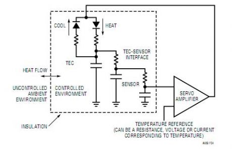
TEC Control Loop Model
Published:2013/2/25 20:17:00 Author:muriel | Keyword: TEC Control Loop Model
View full Circuit Diagram | Comments | Reading(875)
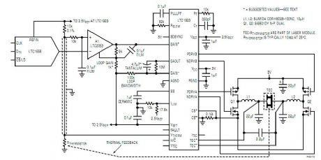
TEC Temperature Controller
Published:2013/2/25 20:15:00 Author:muriel | Keyword: TEC Temperature Controller
View full Circuit Diagram | Comments | Reading(997)
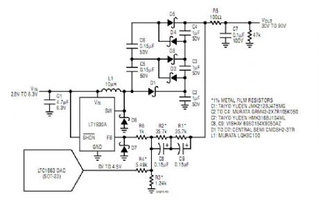
Based Boost Regulator
Published:2013/2/25 20:12:00 Author:muriel | Keyword: Based Boost Regulator
View full Circuit Diagram | Comments | Reading(843)
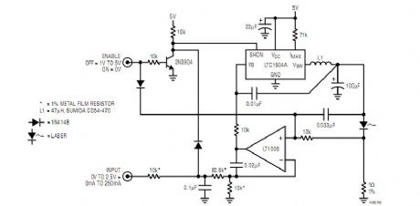
Switching Regulator
Published:2013/2/25 19:54:00 Author:muriel | Keyword: Switching Regulator
View full Circuit Diagram | Comments | Reading(746)
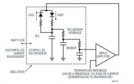
Simplified TEC Control Loop Model Showing Thermal Terms
Published:2013/2/25 19:48:00 Author:muriel | Keyword: Simplified , TEC Control , Loop Model, Thermal Terms
View full Circuit Diagram | Comments | Reading(861)
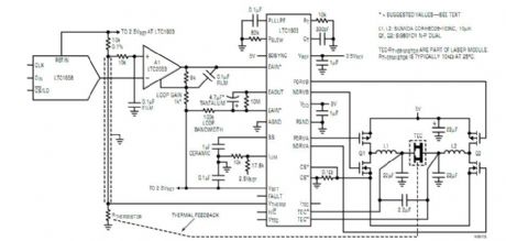
Detailed Schematic of TEC Temperature Controller
Published:2013/2/25 19:45:00 Author:muriel | Keyword: TEC Temperature Controller
View full Circuit Diagram | Comments | Reading(2970)
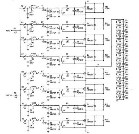
TESLA COIL DRIVER 2
Published:2013/2/24 21:20:00 Author:muriel | Keyword: TESLA COIL , DRIVER
View full Circuit Diagram | Comments | Reading(2555)
Proximity Switch
Published:2013/2/24 21:01:00 Author:muriel | Keyword: Proximity Switch
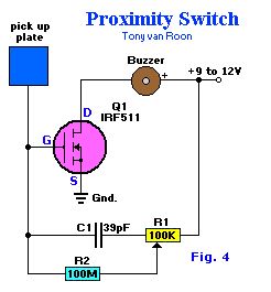
Proximity Switch. This design takes advantage of the ultra-high input impedance and power-handling capabilities of the IRF511 to make a simple, but sensitive, proximity sensor and alarm driver circuit.A 3x3-inch piece of circuit board (or similar size metal object), which functions as the pick-up sensor, is connected to the gate of Q1. A 100 MegaOhm resistor, R2, isolates Q1's gate from R1, allowing the input impedance to remain very high. If a 100-MegaOhm resistor cannot be located, just tie 5 22-MegaOhm resistors in series and use that combination for R2. In fact, R2 can be made even higher in value for added sensitivity.Potentiometer R1 is adjusted to a point where the piezo buzzer just begins to sound off and then carefully backed off to the point where the sound ceases. Experimenting with the setting of R1 will help in obtainin the best sensitivity adjustment for the circuit. Potentiometer R1 may be set to a point where the pick-up must be contacted to set of the alarm sounder. A relay or other current-hungry component can take the place of the piezo sounder to control almost any external circuit
(View)
View full Circuit Diagram | Comments | Reading(0)
Relay-Controller
Published:2013/2/24 21:00:00 Author:muriel | Keyword: Relay-Controller
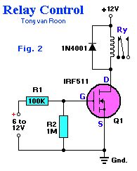
Relay-Controller. With zero-gate bias applied, Q1 acts lilke an open switch, but when a DC voltage greater than 5 volts is applied to the input of the circuit, Q1 turns on, completing the relay circuits and therby activating the relay coil.The input bias current required to turn on Q1 and operate the relay is less than 10 uA (microAmps), which is about 1/1,000,000 of the current required to bias the popular 2N3055 power transistor to operate the same relay.R1 protects whatever's driving the MOSFET and filters against very short transients--together with (mainly) the gatet capacitance. The MOSFET doesn't need protection (as long as it never sees more than 12V), as its gate is insulated. For faster switching, use 100 ohm rather than 100K.R2 is only needed if the circuit driving it doesn't return to ground - to make sure it turns off. For fast OFF times, use as low an impedance as the driving circuit can safely handle.If driven from a (weak) CMOS gate from the 4K series (e.g. a 4093) as a Vdd of 12V, you could use 1K (or even lower) for R1 - and leave out R2 as the gates output goes to ground anyway. (View)
View full Circuit Diagram | Comments | Reading(1792)
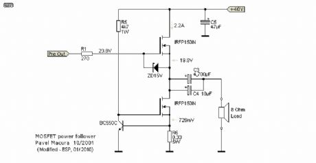
Pavel's Latest Version Direct Coupled Power Follower
Published:2013/2/24 20:53:00 Author:muriel | Keyword: Latest Version , Direct Coupled, Power Follower
View full Circuit Diagram | Comments | Reading(0)
Direct Coupled Power Follower Using MOSFET Current Source
Published:2013/2/24 20:53:00 Author:muriel | Keyword: Direct Coupled, Power Follower, MOSFET, Current Source
View full Circuit Diagram | Comments | Reading(2212)
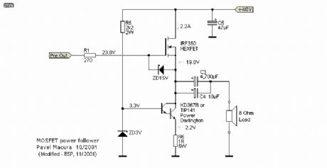
Power Follower Modified for Direct Coupling
Published:2013/2/24 20:52:00 Author:muriel | Keyword: Power Follower , Direct Coupling
View full Circuit Diagram | Comments | Reading(818)
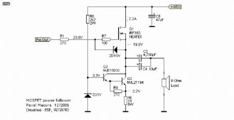
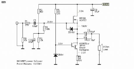
MOSFET POWER FOLLOWER
Published:2013/2/24 20:51:00 Author:muriel | Keyword: MOSFET POWER FOLLOWER
View full Circuit Diagram | Comments | Reading(1409)
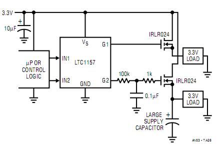
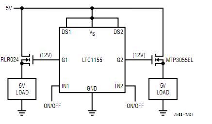
Dual High Side 3.3V Switch
Published:2013/2/24 20:44:00 Author:muriel | Keyword: Dual , High Side , 3.3V , Switch
View full Circuit Diagram | Comments | Reading(855)
Quad High Side Switch for Laptop Computer Power Load Management
Published:2013/2/24 20:43:00 Author:muriel | Keyword: Quad , High Side, Switch , Laptop Computer, Power Load Management

View full Circuit Diagram | Comments | Reading(814)
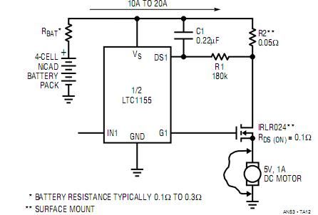
Surface Mount MOSFET Switch
Published:2013/2/24 20:37:00 Author:muriel | Keyword: Surface Mount , MOSFET Switch
View full Circuit Diagram | Comments | Reading(1001)
Bidirectional Switch Using Two “Back-to-Back” MOSFETs
Published:2013/2/24 20:35:00 Author:muriel | Keyword: Bidirectional Switch, “Back-to-Back” MOSFETs
View full Circuit Diagram | Comments | Reading(4571)
Adding 12V VGS Clamps when VS > 9V
Published:2013/2/24 20:33:00 Author:muriel | Keyword: 12V VGS Clamps , VS > 9V
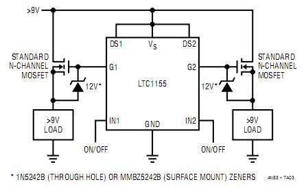
9V src= /uploadfile/ic-circuit/2013224203119446.jpg border=0> (View)
View full Circuit Diagram | Comments | Reading(923)
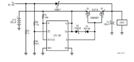
High Efficiency Dual High Side Switch
Published:2013/2/24 20:30:00 Author:muriel | Keyword: High Efficiency , Dual High Side, Switch
View full Circuit Diagram | Comments | Reading(733)
Matching MOSFET Drivers to MOSFETs
Published:2013/2/24 20:29:00 Author:muriel | Keyword: Matching MOSFET Drivers, MOSFETs
View full Circuit Diagram | Comments | Reading(1493)
| Pages:23/312 At 202122232425262728293031323334353637383940Under 20 |
Circuit Categories
power supply circuit
Amplifier Circuit
Basic Circuit
LED and Light Circuit
Sensor Circuit
Signal Processing
Electrical Equipment Circuit
Control Circuit
Remote Control Circuit
A/D-D/A Converter Circuit
Audio Circuit
Measuring and Test Circuit
Communication Circuit
Computer-Related Circuit
555 Circuit
Automotive Circuit
Repairing Circuit