
Control Circuit
Index 20
Voltage Controlled Panner
Published:2013/4/18 2:02:00 Author:muriel | Keyword: Voltage Controlled , Panner
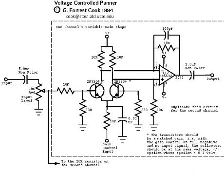
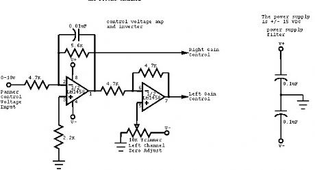
This circuit is used to convert a mono audio signal into a stereo signal that can be panned between the left and right channel by a 0-10V control signal, it is intended for analog synthesizer systems.
(View)
View full Circuit Diagram | Comments | Reading(2594)
Doorknob Proximity Alarm for wooden door
Published:2013/4/18 1:57:00 Author:muriel | Keyword: Doorknob Proximity Alarm, wooden door
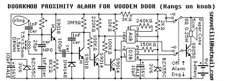
Reverse engineered circuit diagram of a popular retail doorknob alarm. It contains a small transmitter and the doorknob acts as an antenna so it will not work on a metal door. When a person comes close to the doorknob this loads down the oscillator and the alarm sounds. The proximity sensor circuitry is perfectly capable of driving 74HCT series CMOS logic in place of of the sound effect IC's shown in the circuit diagram.
(View)
View full Circuit Diagram | Comments | Reading(1458)
Electronic combination lock with PIC Microcontroller
Published:2013/4/18 1:56:00 Author:muriel | Keyword: Electronic combination lock, PIC Microcontroller

This is my electronic combination lock to use with an outdoor gate. The functionality is implemented in software. It turns on a relay (usually to open a door) for a few seconds if someone enters the valid code. Alternatively, it works as an ON/OFF switch, which toggles the relay each time the code is entered. This relay can operate a power-to-open type electric strike with a shorting contact or a power-to-hold type electromagnetic lock with a breaking contact (we need the relay because these locks usually work with AC, not DC). The code can be changed any time after entering the current code.
Current consumption of the circuit is low, because the PIC sleeps most of the time, and wakes up only for processing key presses. If you don't have a crystal, you can use the RC oscillator of the PIC16F84 as well, just check the PIC datasheets for details on oscillator configurations. The 16F628 already contains an internal RC oscillator, so no crystal is needed.
(View)
View full Circuit Diagram | Comments | Reading(2036)
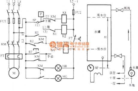
Electrical contacts level electronic control circuit
Published:2013/4/6 22:30:00 Author:Ecco | Keyword: Electrical contacts, level , electronic control

Electrical contacts level electronic control circuit is shown as figure.
(View)
View full Circuit Diagram | Comments | Reading(1986)
Electrical contacts controlled pump circuit 2
Published:2013/4/6 22:31:00 Author:Ecco | Keyword: Electrical contacts controlled pump
Electrical contacts controlled pump circuit 2 is shown as figure.
(View)
View full Circuit Diagram | Comments | Reading(1395)
The motor protection circuit with leakage relay
Published:2013/4/3 3:56:00 Author:Ecco | Keyword: motor protection
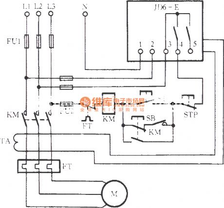
The motor protection circuit with leakage relay is shown as figure.
(View)
View full Circuit Diagram | Comments | Reading(1327)
Digital Volume Control electronic circuit diagram
Published:2013/4/1 3:11:00 Author:Ecco | Keyword: Digital Volume Control
This digital volume control has no pot to wear out and introduces almost no noise in the circuit. Instead, the volume is controlled by pressing UP and DOWN buttons. This simple circuit would be a great touch to any home audio project.
(View)
View full Circuit Diagram | Comments | Reading(1612)
Audio Perimeter Monitor electronic circuit
Published:2013/4/1 3:05:00 Author:Ecco | Keyword: Audio Perimeter Monitor
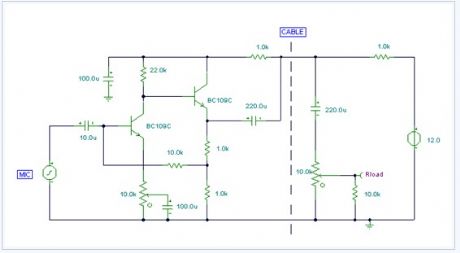
Using a single cable such as speaker wire or doorbell cable, this circuit can be remotely positioned, for example, at the bottom of a garden or garage, and used to detect all sound in that area. The cable can be buried in a hosepipe or duct and is concealed out of sight. The mic is an ordinary dynamic mic insert and should be housed in a waterproof enclosure with the rest of the circuit. The mic output is amplified by the two transistors, the output is fed down the cable via the 220u capacitor. Here, it has a dual purpose of preventing the DC supply from upsetting the bias of the circuit, and also allowing the smaller ac audio output to pass down the line. At the power supply, the audio is recovered by the 10k preset and 220u capacitor. It is used to feed a small audio amplifier (such as the 2watt design) shown earlier on this site.
(View)
View full Circuit Diagram | Comments | Reading(1062)
Automatic Loudness Control electronic circuit
Published:2013/4/1 3:03:00 Author:Ecco | Keyword: Automatic Loudness Control
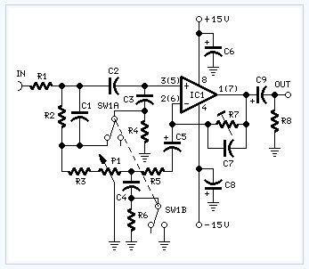
In order to obtain a good audio reproduction at different listening levels, a different tone-controls setting should be necessary to suit the well known behaviour of the human ear. In fact, the human ear sensitivity varies in a non-linear manner through the entire audible frequency band, as shown by Fletcher-Munson curves.A simple approach to this problem can be done inserting a circuit in the preamplifier stage, capable of varying automatically the frequency response of the entire audio chain in respect to the position of the control knob, in order to keep ideal listening conditions under different listening levels.Fortunately, the human ear is not too critical, so a rather simple circuit can provide a satisfactory performance through a 40dB range.The circuit is shown with SW1 in the Control-flat position, i.e. without the Automatic Loudness Control. In this position the circuit acts as a linear preamplifier stage, with the voltage gain set by means of Trimmer R7.Switching SW1 in the other position the circuit becomes an Automatic Loudness Control and its frequency response varies in respect to the position of the control knob by the amount shown in the table below.C1 boosts the low frequencies and C4 boosts the higher ones. Maximum boost at low frequencies is limited by R2; R5 do the same at high frequencies.
(View)
View full Circuit Diagram | Comments | Reading(1794)
Bass-treble Tone Control Circuit electronic circuit diagram
Published:2013/4/1 3:02:00 Author:Ecco | Keyword: Bass-treble Tone Control
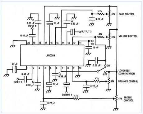
The LM1036 is a DC controlled tone (bass/treble), volume and balance circuit for stereo applications in car radio, TV and audio systems. An additional control input allows loudness compensation to be simply effected. Four control inputs provide control of the bass, treble, balance and volume functions through application of DC voltages from a remote control system or, alternatively, from four potentiometers which may be biased from a zener regulated supply provided on the circuit. Each tone response is defined by a single capacitor chosen to give the desired characteristic.
(View)
View full Circuit Diagram | Comments | Reading(3175)
Mixer or Sewing Machine Motor Speed Control circuit
Published:2013/3/29 4:39:00 Author:Ecco | Keyword: Mixer or Sewing Machine, Motor Speed Control
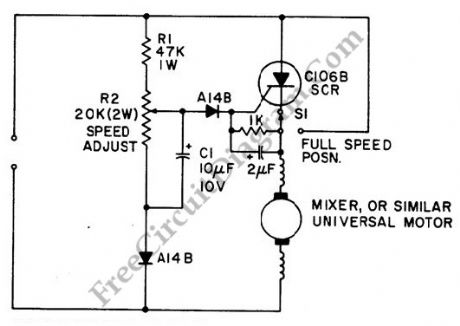
It will be effective to use simple half wave motor speed control with small universal ac/dc motors. Two amps RMS is the maximum current capability. The control gives excellent torque characteristics to the motor because speed dependent feedback is provided, even at low rotation speeds. By closing switch S1, thus bypassing the SCR, we can achieve normal operation at maximum speed.
(View)
View full Circuit Diagram | Comments | Reading(3855)
General Purpose Alarm Circuit for Resistive Sensor circuit
Published:2013/3/29 4:35:00 Author:Ecco | Keyword: General Purpose Alarm , Resistive Sensor
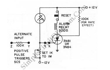
When the resistance value of a temperature, light, pressure, or any other resistive sensors Rs drops below a certain point (adjusted by a preset potentiometer), the SCR (silicon controlled switch) will be triggered. The sensor (Rs) and the potentiometer placement can be interchanged to get opposite action, where the SCR need to be triggered at the increase of sensing resistor (Rs). Here is the schematic diagram of the circuit:
(View)
View full Circuit Diagram | Comments | Reading(1354)
Series-Wound Direction And Speed Motor Control circuit
Published:2013/3/29 4:30:00 Author:Ecco | Keyword: Series-Wound Direction , Speed Motor Control
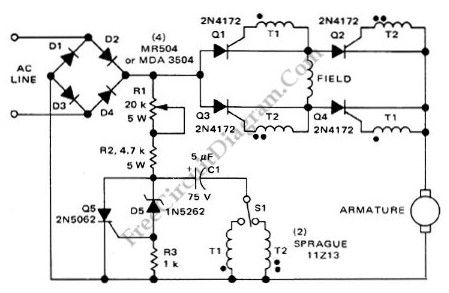
This is a motor controller circuit that control the speed and direction of series-wound Motors. This circuit employs silicon controlled rectifiers (SCR) Q1-Q4, that are triggered in diagonal pairs. The switch St is used to control which pair is turned on because either coupling transformer T2 or coupling transformer T1 is connected to a pulsing circuit by this switch. Here is the schematic diagram of the circuit:
(View)
View full Circuit Diagram | Comments | Reading(1338)
Series-Wound Direction And Speed Motor Control
Published:2013/3/29 4:29:00 Author:Ecco | Keyword: Series-Wound Direction , Speed Motor Control

This is a motor controller circuit that control the speed and direction of series-wound Motors. This circuit employs silicon controlled rectifiers (SCR) Q1-Q4, that are triggered in diagonal pairs. The switch St is used to control which pair is turned on because either coupling transformer T2 or coupling transformer T1 is connected to a pulsing circuit by this switch. Here is the schematic diagram of the circuit:
(View)
View full Circuit Diagram | Comments | Reading(1045)
Logic Power Control circuit diagram for 78xx Regulator
Published:2013/3/28 4:12:00 Author:Ecco | Keyword: Logic Power Control , 78xx Regulator
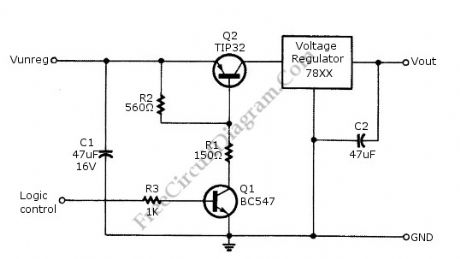
Logic power control of analog regulator can be useful in application where a digital circuit/controller need to control power source, such as in EEPROM programmer or other power controls. This is a circuit provide ON-OFF control for 78xx regulator using digital (TTL or CMOS) signal level. This circuit uses transistors in series with the 78XX regulator, which it’s base is controlled by logic level input. Here is the schematic diagram of the circuit:
(View)
View full Circuit Diagram | Comments | Reading(2390)
PCB Drill Speed Controller with 555
Published:2013/3/27 4:24:00 Author:Ecco | Keyword: PCB Drill Speed, Controller
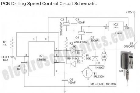
Described here is a simple, inexpensive and useful circuit for electronics hobbyists. The circuit is nothing but a PCB drill speed controller, which can be used to control the speed of any 12VDC small pcb drilling units. Such portable units are now widely available, and even a hobbyist can make it without too much difficulty.
(View)
View full Circuit Diagram | Comments | Reading(1848)
Arduino Panic Alarm
Published:2013/3/27 4:16:00 Author:Ecco | Keyword: Arduino Panic Alarm
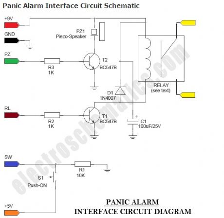
Panic Alarm circuit consists of two equally important parts. The first part is the ready-made Arduino Microcontroller board, and the second part is an interface circuit which can be wired on a piece of prototyping board. You can use any standard 9V battery to power the whole circuit, and the Push-ON (push ‘n’ hold) switch (S1) to activate the alarm function. An additional Electro-Magnetic Relay (EMR) is also attached to the interface circuit.
(View)
View full Circuit Diagram | Comments | Reading(1424)
12V Stereo Tone Control
Published:2013/3/27 3:54:00 Author:Ecco | Keyword: 12V , Stereo Tone Control
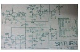
The following diagram is the circuit diagram of 12V stereo tone control which also available in kit, you may find the kit at electronic part store around your place. The circuit build based on ordinary tone control circuit, using 2 transistors FCS9014 in each channel, so there are will be 4 transistors in this 12v stereo tone control.
(View)
View full Circuit Diagram | Comments | Reading(1543)
ACTOR : Active Tone Control
Published:2013/3/27 3:52:00 Author:Ecco | Keyword: ACTOR, Active Tone Control
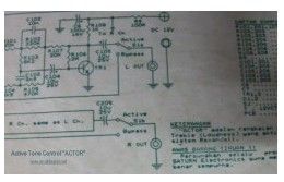
The following diagram is the schematic diagram of Active Tone Control circuit, or we often call thic circuit as “ACTOR” Active Tone Control or ACTOR is a electronic audio circuit that serves to increase the Loudness (Bass and Treble audio signal) is active because it uses the Baxandall system.
(View)
View full Circuit Diagram | Comments | Reading(1151)
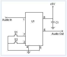
Stereo Digital Volume Control
Published:2013/3/25 4:26:00 Author:Ecco | Keyword: Stereo Digital, Volume Control
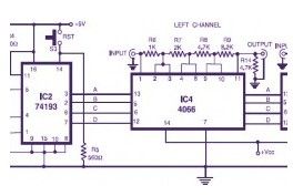
Here is the circuit diagram of stereo digital volume control. This circuit could possibly be applied for upgrading your manual volume management within a stereo amplifier circuit. In this particular circuit, push-to-on switch S1 controls the forward (volume enhance) operation of the two channels while a identical switch S2 controls reverse (volume reduce) operation of the two channels.
(View)
View full Circuit Diagram | Comments | Reading(4163)
| Pages:20/312 1234567891011121314151617181920Under 20 |
Circuit Categories
power supply circuit
Amplifier Circuit
Basic Circuit
LED and Light Circuit
Sensor Circuit
Signal Processing
Electrical Equipment Circuit
Control Circuit
Remote Control Circuit
A/D-D/A Converter Circuit
Audio Circuit
Measuring and Test Circuit
Communication Circuit
Computer-Related Circuit
555 Circuit
Automotive Circuit
Repairing Circuit