
Control Circuit
Index 8
TILT SWITCH
Published:2013/8/1 22:27:00 Author:lynne | Keyword: TILT SWITCH
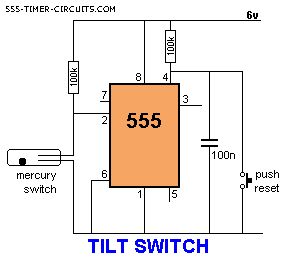
The output is LOW at start-up due to the capacitor on pin 4. When the mercury switch closes, the output goes HIGH and remains HIGH until the reset button is pressed. This circuit is called a LATCH. (View)
View full Circuit Diagram | Comments | Reading(1282)
TOUCH SWITCH and TOUCH ON-OFF
Published:2013/8/1 22:25:00 Author:lynne | Keyword: TOUCH SWITCH and TOUCH ON-OFF
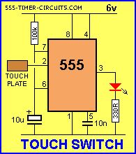
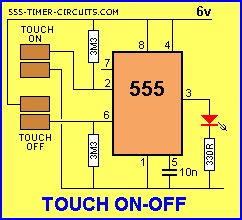
The Touch Switch circuit will detect stray voltages produced by mains voltages and electrostatic build-up in a room. In the first circuit, pin 2 must see a LOW for the circuit to activate. If sufficient static voltage is detected by the plate, the chip will change state. If not, you will need to touch the plate and the 0v rail. In the second circuit, two touch plates are provided and the resistance of your finger changes the voltage on pin 2 or 6 to toggle the 555.
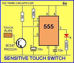
The circuit can be made 100 times more sensitive by adding a transistor to the front-end as shown in the diagram below:
(View)
View full Circuit Diagram | Comments | Reading(3139)
TRAFFIC LIGHTS
Published:2013/8/1 4:47:00 Author:lynne | Keyword: TRAFFIC LIGHTS
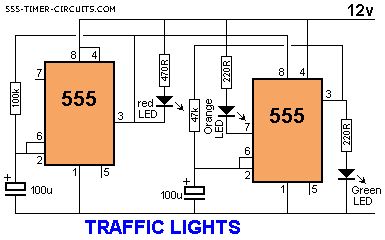
Here's a clever circuit using two 555's to produce a set of traffic lights for a model layout. The animation shows the lighting sequence and this follows the Australian-standard. The red LED has an equal on-off period and when it is off, the first 555 delivers power to the second 555. This illuminates the Green LED and then the second 555 changes state to turn off the Green LED and turn on the Orange LED for a short period of time before the first 555 changes state to turn off the second 555 and turn on the red LED. A supply voltage of 9v to 12v is needed because the second 555 receives a supply of about 2v less than rail. This circuit also shows how to connect LEDs high and low to a 555 and also turn off the 555 by controlling the supply to pin 8. Connecting the LEDs high and low to pin 3 will not work and since pin 7 is in phase with pin 3, it can be used to advantage in this design. (View)
View full Circuit Diagram | Comments | Reading(1701)
Photo Timer Circuit
Published:2013/7/30 20:46:00 Author:muriel | Keyword: Photo Timer Circuit
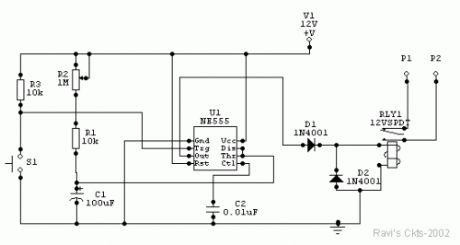
Time is set by potentiometer R2 which provides a range or 1 sec. To 100 seconds with timing capacitor C1 of 100uF. The output at pin 3 is normally low and the relay is held off. A momentary push on switch S1 energies the relay which is held closed for a time 1.1 X (R1+R2). C1 and then released. The exact length of the timing interval will depend on the actual capacitance of C1. Most electrolytic capacitors are rated on the basis of minimum guaranteed value and the actual value may be higher. The circuit should be calibrated for various positions of the control knob of R2 after the timing capacitor has had a chance to age. Once the capacitor has reached its stable value, the timings provided should be well within the photographic requirements.
PartsC1 - 100uF, 25V electrolyticC2 - 0.01uF, disc ceramicD1, D2 - DR50 or 1N4001R!,R2 - 10K ohms, ¼ wattsR3 - 1 M ohms, potentiometerRLY1 - 12V, DC relay, operating current less than 200mAS1 - Push-to-on switchU1 - NE555 timer ICP1 & P2 are for exposure lamp ckt. (View)
View full Circuit Diagram | Comments | Reading(1087)
Amplifier Timers
Published:2013/7/30 20:45:00 Author:muriel | Keyword: Amplifier Timers
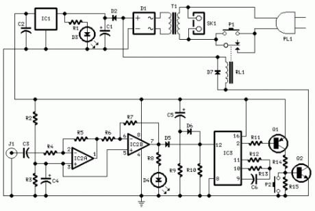
Parts:R1,R8 1K 1/4W ResistorsR2,R3 4K7 1/4W ResistorsR4 22K 1/4W ResistorR5 4M7 1/4W ResistorR6,R9 10K 1/4W ResistorsR7 1M5 1/4W ResistorR10 100K 1/4W ResistorR11 15K 1/4W ResistorR12 10M 1/4W ResistorR13 1M 1/4W ResistorR14 8K2 1/4W ResistorR15 1K8 1/4W ResistorC1 470µF 25V Electrolytic CapacitorC2,C3,C6 100nF 63V Polyester CapacitorsC4,C5 10µF 25V Electrolytic CapacitorsD1 Diode bridge 100V 1A D2,D7 1N4002 100V 1A DiodesD3 Red LED 5mm.D4 Yellow LED 5mm.D5,D6 1N4148 75V 150mA DiodesIC1 78L12 12V 100mA Voltage regulator ICIC2 LM358 Low Power Dual Op-ampIC3 4060 14 stage ripple counter and oscillator ICQ1 BC557 45V 100mA PNP TransistorQ2 BC337 45V 800mA NPN TransistorJ1 RCA audio input socketP1 SPST Mains suited PushbuttonP2 SPST PushbuttonT1 220V Primary, 12V Secondary 3VA Mains transformerRL1 10.5V 270 Ohm Relay with SPST 5A 220V switchPL1 Male Mains plugSK1 Female Mains socket
Circuit operation:This circuit turns-off an amplifier or any other device when a low level audio signal fed to its input is absent for 15 minutes at least.Pushing P1 the device is switched-on feeding any appliance connected to SK1. Input audio signal is boosted and squared by IC2 A & B and monitored by LED D4. When D4 illuminates, albeit for a very short peak, IC3 is reset and restarts its counting. Pin 2 of IC3 remains at the low state, the two transistors are on and the relay operates. When, after a 15 minutes delay, no signal appeared at the input, IC3 ends its counting and pin 2 goes high. Q1 & Q2 stop conducting and the relay switches-off. The device is thus completely off as also are the appliances connected to SK1. C5 & R9 reset IC3 at power-on. P2 allows switch-off at any moment.
Notes:Simply connect left or right channel tape output of your amplifier to J1.You can employ two RCA input sockets wired in parallel to allow pick-up audio signals from both stereo channels.The delay time can be varied changing R13 and/or C6 values.Needing to operate a device not supplied by power mains, use a double pole relay switch, connecting the second pole switch in series with the device's supply. (View)
View full Circuit Diagram | Comments | Reading(961)
Timed Beepers
Published:2013/7/30 20:44:00 Author:muriel | Keyword: Timed Beepers
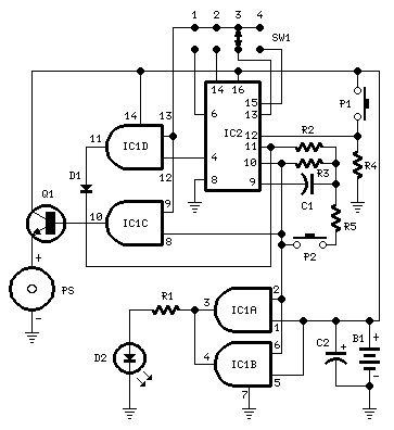
Beeps 7.5 seconds after a preset timeAdjustable time settings: 15 sec. 30 sec. 1 min. 2 min. & others
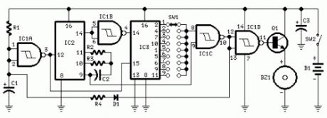
Parts:R1 220R 1/4W ResistorR2 10M 1/4W ResistorR3 1M 1/4W ResistorR4 10K 1/4W ResistorR5 47K 1/4W ResistorC1 100nF 63V Polyester CapacitorC2 22µF 25V Electrolytic CapacitorD1 1N4148 75V 150mA DiodeD2 3mm. Red LEDIC1 4081 Quad 2 input AND Gate ICIC2 4060 14 stage ripple counter and oscillator ICQ1 BC337 45V 800mA NPN TransistorP1 SPST Pushbutton (Start)P2 SPST Pushbutton (Reset)SW1 4 ways Switch (See notes)PS Piezo sounder (incorporating 3KHz oscillator)B1 3V Battery (2 AA 1.5V Cells in series)
Device purpose:This circuit is intended for alerting purposes after a certain time is elapsed. It is suitable for table games requiring a fixed time to answer a question, or to move a piece etc. In this view it's a modern substitute for the old sandglass. Useful also for time control when children are brushing teeth (at least two minutes!), or in the kitchen, and so on.
Circuit operation:Pushing P1 resets IC2 that start oscillating at a frequency fixed by R3 & C1. With values shown, this frequency is approx. 4Hz. The LED D2, driven by IC1A & B, flashing at the same oscillator frequency, signals proper circuit operation. SW1 selects the appropriate pin of IC2 thus adjusting timing duration:Position 1 = 15 secondsPosition 2 = 30 secondsPosition 3 = 1 minutePosition 4 = 2 minutes When the selected pin of IC2 goes high, IC1C drives Q1 and the piezo sounder beeps intermittently at the same frequency of the LED. After approx. 7.5 seconds pin 4 of IC2 goes high and IC1D stops the oscillator through D1. If you want to stop counting in advance, push P2.
Notes:SW1 can be any type of switch with the desired number of ways. If you want a single fixed timing duration, omit the switch and connect pins 9 & 13 of IC1 to the suitable pin of IC2.The circuit's reset is not immediate. Pushing P2 forces IC2 to oscillate very fast, but it takes some seconds to terminate the counting, especially if higher timer's duration is chosen and the pushbutton is operated when the circuit has just started. In order to speed the reset, try lowering the value of R5, but pay attention: too low a value can stop oscillation.Frequency operation varies with different brand names for IC2. E.g. Motorola's ICs run faster, therefore changing of C1 and/or R3 values may be necessary.You can also use pins 1, 2, 3 of IC2 to obtain timings of 8, 16 and 32 minutes respectively.An on-off switch is not provided because in the off state the circuit draws no significant current. (View)
View full Circuit Diagram | Comments | Reading(1294)
Tan Timers
Published:2013/7/30 20:43:00 Author:muriel | Keyword: Tan Timers
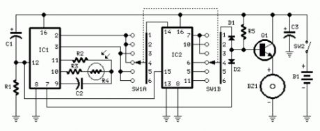
Parts:R1 47K 1/4W ResistorR2 1M 1/4W ResistorR3,R5 120K 1/4W ResistorsR4 Photo resistor (any type)C1,C3 10µF 25V Electrolytic CapacitorsC2 220nF 63V Polyester CapacitorD1,D2 1N4148 75V 150mA DiodesIC1 4060 14 stage ripple counter and oscillator ICIC2 4017 Decade counter with 10 decoded outputs ICQ1 BC337 45V 800mA NPN TransistorSW1 2 poles 6 ways Rotary Switch (see notes)SW2 SPST Slider SwitchBZ1 Piezo sounder (incorporating 3KHz oscillator)B1 3V Battery (two 1.5V AA or AAA cells in series etc.)
Device purpose:This timer was deliberately designed for people wanting to get tanned but at the same time wishing to avoid an excessive exposure to sunlight.A Rotary Switch sets the timer according to six classified Photo-types (see table).A Photo resistor extends the preset time value according to sunlight brightness (see table).When preset time ends, the beeper emits an intermittent signal and, to stop it, a complete switch-off of the circuit via SW2 is necessary.Photo-type, Features and Exposure timeI & children Light-eyed, red-haired, light complexion, freckly 20 to 33 minutesII Light-eyed, fair-haired, light complexion 28 to 47 minutesIII Light or brown-eyed, fair or brown-haired, light or slightly dark complexion 40 to 67 minutesIV Dark-eyed, brown-haired, dark complexion 52 to 87 minutesV Dark-eyed, dark-haired, olive complexion 88 to 147 minutesVI The darkest of all 136 to 227 minutes[color=green]Note that pregnant women belong to Photo-type I[/color]
Notes:Needing only one time set suitable for your own skin type, the rotary switch can be replaced by hard-wired links.A DIP-Switch can be used in place of the rotary type. Pay attention to use only a switch at a time when the device is off, or the ICs could be damaged. (View)
View full Circuit Diagram | Comments | Reading(963)
Periodic Timers
Published:2013/7/30 20:43:00 Author:muriel | Keyword: Periodic Timers
A switched timer with equal make and equal space periods timing adjustable from over 6 minutes to 38 minutes.
Notes:This timer circuit is similar to the 5 to 30 minute timer except that when switch S1 is closed, the on/off action of the circuit will continue indefinately until S1 is opened again. A 7555 time and low leakage type capacitor for C1 must be used. The 6 way rotary switch S3 adds extra resistance in series to the timing chain with each rotation, minimum resistance point a maximum point f . The 7555 is wired as an equal mark/space ratio oscillator, the timing resistor chain R1 to R6, being connected back to the output of the timer at pin 3.The output pulse duration is defined as:-
T = 1.4 R1 C1
This gives on and off times of about 379 seconds for postion a of S3 (just over 6 minutes), to about 38 minutes at point f . The times may of coourse be varied by altering R1 to R6 or C1. (View)
View full Circuit Diagram | Comments | Reading(1150)
5 to 30 Minute Timers
Published:2013/7/30 20:36:00 Author:muriel | Keyword: 5 to 30 Minute , Timers

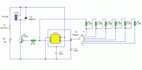
Notes:Simple to build, simple to make, nothing too complicated here. However you must use the CMOS type 555 timer designated the 7555, a normal 555 timer will not work here due to the resistor values. Also a low leakage type capacitor must be used for C1, and I would strongly suggest a Tantalum Bead type. Switch 3 adds an extra resistor in series to the timing chain with each rotation, the timing period us defined as :-
Timing = 1.1 C1 x R1
Note that R1 has a value of 8.2M with S3 at position a and 49.2M at position f . This equates to just short of 300 seconds for each position of S3. C1 and R1 through R6 may be changed for different timing periods. The output current from Pin 3 of the timer, is amplified by Q1 and used to drive a relay.
Parts Relay 9 volt coil with c/o contact (1)S1 On/Off (1)S2 Start (1)S3 Range (1)IC1 7555 (1)B1 9V (1)C1 33uF CAP (1)Q1 BC109C NPN (1)D1 1N4004 DIODE (1)C2 100n CAP (1)R6,R5,R4,R3,R2,R1 8.2M RESISTOR (6)R8 100k RESISTOR (1)R7 4.7k RESISTOR (1) (View)
View full Circuit Diagram | Comments | Reading(965)
Jogging Timers
Published:2013/7/30 20:31:00 Author:muriel | Keyword: Jogging Timers
Parts:R1 47K 1/4W ResistorR2 10M 1/4W ResistorR3 1M 1/4W ResistorR4 12K 1/4W Resistor (see notes)C1,C3 10µF 25V Electrolytic CapacitorsC2 100nF 63V Polyester CapacitorD1 1N4148 75V 150mA DiodeIC1 4093 Quad 2 input Schmitt NAND Gate ICIC2 4060 14 stage ripple counter and oscillator ICIC3 4017 Decade counter with 10 decoded outputs ICQ1 BC337 45V 800mA NPN TransistorSW1 1 pole 9 ways Rotary Switch (see notes)SW2 SPST Slider SwitchBZ1 Piezo sounder (incorporating 3KHz oscillator)B1 3V Battery (two 1.5V AA or AAA cells in series etc.)
Device purpose:This circuit was developed since a number of visitors of this website requested a timer capable of emitting a beep after one, two, three minutes and so on, for jogging purposes.As shown in the Circuit diagram, SW1 is a 1 pole 9 ways Rotary Switch. Setting the switch in position 1, the Piezo sounder emits three short beeps every minute. In position 2 the same thing happens after 2 minutes, and so on, reaching a maximum interval of 9 minutes in position 9.
Notes:Needing only one time set, rotary switch can be replaced by an hard-wired link.A DIP-Switch can be used in place of the rotary type. Pay attention to use only a switch at a time, or the device could be damaged.Varying R4 from 10K to 15K you can obtain more or less than three short beeps after the preset time delay.To obtain a one-second beep only, after the preset time delay, disconnect pin 9 of IC1C from pin 9 of IC2 and connect it to pin 8 of IC1C. (View)
View full Circuit Diagram | Comments | Reading(1032)
Repeating Interval Timers
Published:2013/7/30 20:30:00 Author:muriel | Keyword: Repeating Interval Timers
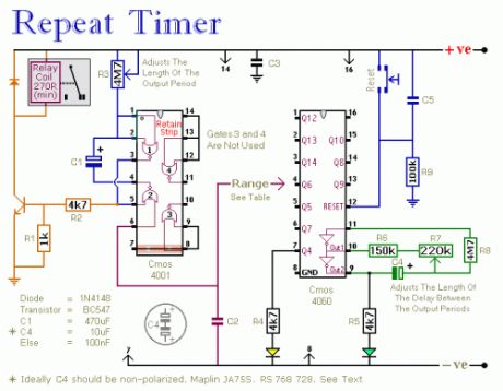
This circuit has an adjustable output timer that will re-trigger at regular intervals. The output period can be anything from a fraction of a second to half-an-hour or more - and it can be made to recur at regular intervals of anything from seconds to days and beyond.
The Output Section:The output section is a simple Monostable Circuit. When Pin 6 of the Cmos 4001 is taken high - the monostable triggers - and the relay energizes. It will remain energized for a period of time set by C1 & R3.With the values shown - R3 will provide output periods of up to about 30-minutes. However, you can choose component values to suit your requirements. For example, if you reduce R3 to 1meg - and C1 to 4.7uF - the maximum output period is between 3 and 5 seconds. Owing to manufacturing tolerances - the precise length of the time period available depend on the characteristics of the actual components you've used.
The Cmos 4060:The Cmos 4060 is a 14-bit binary counter with a built-in oscillator. The oscillator consists of the two inverters connected to Pins 9, 10 & 11 - and its frequency is controlled by R7. The output from the oscillator is connected internally to the binary counter. While the oscillator is running - the IC counts the number of oscillations - and the state of the count is reflected in the output pins.By adjusting R7 - you can set the length of time it takes for any given output pin to go high. Connect that output to Pin 6 of the Cmos 4001 and - every time it goes high - it'll trigger the monostable.Ideally C4 should be non-polarized - but a regular electrolytic will work - provided it doesn't leak too badly in the reverse direction. Alternatively - you can simulate a non-polarized 10uF capacitor by connecting two 22uF capacitors back to back - as shown. (View)
View full Circuit Diagram | Comments | Reading(1274)
Simple optical switch
Published:2013/7/29 20:23:00 Author:muriel | Keyword: Simple optical switch
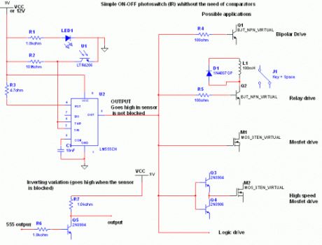
IntroductionThe 555 is proved to be the most versatile and ubiquitous IC all over the world.This is a possible use: simple inverting schmitt trigger.
Circuit explanationWhen the phototransistor is stroken by IR light it conducts and the voltage between the 1Mohm resistor(arbitrary) and the phototrans drops from VCC to lower values. When the voltage drops lower than VCC/3 the 555 is triggered and goes high (from 0 TO VCC). The amount of light that strike the phototrans necessary to bring his collector to VCC/3 is determined by the resistor (Vdrop = Icollector * R , so , if Vdrop= 2*VCC/3, the resistance needed to set the threshold on current is R=2*VCC/(Icollector*3)). High sensibility phototrans would need a smaller resistor, and weaker phototransistors higher value resistor, you can also use a trimmer to set the on threshold level with precision. The time of phototransistor isn't critical. The 555 has high current capability and can drive various devices, such as Bipolars, relays, bipolars+relays, mosfets, mosfets + totem pole , or give a logic output (see pic).In case you need to trigger something when the gate is blocked (for example a burglar alarm, or a multistage coilgun) you need to invert the output, which is accomplished using a small bipolar transistor wired in an inverting setup (see pic) or swapping the positions of phototransistor with the resistor, so the voltage will drop under VCC/3 when blocked: The formula to determine the resistance to turn off at Icollector is R=VCC/(Icollector*3). (View)
View full Circuit Diagram | Comments | Reading(1091)
DC Motor Reversing Circuit
Published:2013/7/29 20:23:00 Author:muriel | Keyword: DC Motor Reversing Circuit
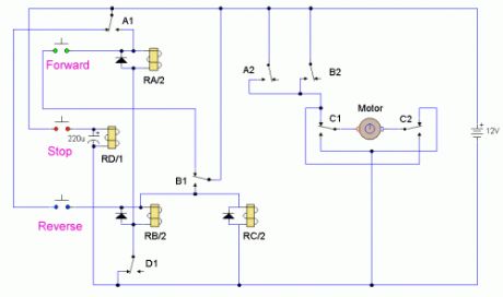
A DC motor reversing circuit using non latching push button switches. Relays control forward, stop and reverse action, and the motor cannot be switched from forward to reverse unless the stop switch is pressed first.
Notes:At first glance this may look over-complicated, but this is simply because three non-latching push button switches are used. When the forward button is pressed and released the motor will run continuously in one direction. The Stop button must be used before pressing the reverse button. The reverse button will cause the motor to run continuously in the opposite direction, or until the stop button is used. Putting a motor straight into reverse would be quite dangerous, because when running a motor develops a back emf voltage which would add to current flow in the opposite direction and probably cause arcing of the relay contacts. This circuit has a built-in safeguard against that condition.
Circuit Operation:Assume that the motor is not running and that all relays are unenergized. When the forward button is pressed, a positive battery is applied via the NC contacts of B1 to the coil of relay RA/2. This will operate as the return path is via the NC contacts of D1. Relay RA/2 will operate. Contacts A1 maintain power to the relay even though the forward button is released. Contacts A2 apply power to the motor which will now run continuously in one direction. If now the reverse button is pressed, nothing happens because the positive supply for the switch is fed via the NC contact A1, which is now open because Relay RA/2 is energized. To Stop the motor the Stop switch is pressed, Relay D operates and its contact D1 breaks the power to relays A and B, (only Relay A is operated at the moment). If the reverse switch is now pressed and released. Relay B operates via NC contact A1 and NC contact D1. Contact B1 closes and maintains power so that the relay is now latched, even when the reverse switch is opened. Relay RC/2 will also be energized and latched. Contact B2 applies power to the motor but as contacts C1 and C2 have changed position, the motor will now run continuously in the opposite direction. Pressing the forward button has no effect as power to this switch is broken via the now open NC contact B1. If the stop button is now pressed. Relay D energizes, its contact D1 breaks power to relay B, which in turn breaks power to relay C via the NO contact of B1 and of course the motor will stop. All very easy. The capacitor across relay D is there to make sure that relay D will operate at least longer than the time relays A,B and C take to release. (View)
View full Circuit Diagram | Comments | Reading(1606)
Infra Red Switches
Published:2013/7/29 20:22:00 Author:muriel | Keyword: Infra Red Switches

This is a single channel (on / off) universal switch that may be used with any Infra Red remote control that uses wavelengths between 850-950nm.
Notes:Any button of any remote control may be used to work this universal switch. The button must be pressed for two seconds (determined by R3 and C2) before the relay will operate. Once operated the circuit will remain in this state (latched) until reset. To reset, any button is pressed and held for the delay.For example, if you were watching TV, and your set was tuned to Channel 3, you could press and hold the TV remote controls channel 3 button for two seconds. That way the TV viewing would not be affected and the relay would activate. You can connect anything to the relay, for example a lamp, but make sure that the relay contacts can handle the rated voltage and current.
Circuit Operation:IC1 is an Infra Red module. IR modulated pulses are received and buffered by this IC. It has a standard TTL output, the output with no signal is logic 1. One gate of a CMOS inverter and drives Red LED1 as a visible switching aid. Another gate buffers the signal and applies it to the time constant circuit, comprising R3,C2,R4 and D1. C2 charges via R3, and discharges via R4, D1 prevents quick discharge via the low output impedance of the CMOS buffer.
The pulses are further buffered and contain jaggered edges as shown above. These edges are produced by the modulated IR data, which has to be removed. This is achieved using IC3, a 555 timer wired as a monostable, pulse duration R5, C4. These cleanly reconstructs a single clean pulse to activate the bistable latch. A D type flip flop, IC4 is configured as a bistable. The input is applied to the clock pin, the inverted output fed back to the data input and clear and preset lines are tied to ground. For every pulse the relay will operate and latch, the next pulse will turn off the relay and so on. Note that quick turn on and off of the relay is not possible. The output pulse is set at about 1.5 seconds and input delay by R3, C2 set at two seconds.
PartsR1 3k3R2 1kR3 22kR4 220kR5 1MR6 3k3B1 12 VD1 1N4148D2 1N4003Q1 B109LED1 CQX35AIC1 IR1 available from Harrison ElectronicsIC2 4049IC3 CA555IC4 SN74HCT74IC5 LM7805Relay 12 Volt coil with changeover contactC1 100uC2 22uC3 100nC4 2u2 (View)
View full Circuit Diagram | Comments | Reading(1189)
Door Alarm circuit
Published:2013/7/29 20:21:00 Author:muriel | Keyword: Door Alarm circuit
Parts:R1 1M 1/4W ResistorR2 3K3 1 or 2W Resistor (See Notes)R3 10K 1/2W Trimmer Cermet (See Notes)R4 33K 1/4W ResistorR5 150K 1/4W ResistorR6 2K2 1/4W ResistorR7 22K 1/4W ResistorR8 4K7 1/4W ResistorC1,C2 10nF 63V Ceramic or Polyester CapacitorsC3 10pF 63V Ceramic CapacitorC4,C6 100nF 63V Ceramic or Polyester CapacitorsC5 2µ2 25V Electrolytic CapacitorC7 100µF 25V Electrolytic CapacitorD1,D2,D4 1N4148 75V 150mA DiodesD3 5 or 3mm. Red LEDQ1,Q2,Q3,Q5 BC547 45V 100mA NPN TransistorsQ4 BC557 45V 100mA PNP TransistorL1 (See Notes)L2 10mH miniature InductorHook (See Notes)BZ1 Piezo sounder (incorporating 3KHz oscillator)SW1,SW2 SPST miniature Slider SwitchesB1 9V PP3 BatteryClip for PP3 Battery
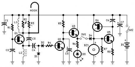
Device purpose:This circuit emits a beep and/or illuminates a LED when someone touches the door-handle from outside. The alarm will sound until the circuit will be switched-off.The entire circuit is enclosed in a small plastic or wooden box and should be hanged-up to the door-handle by means of a thick wire hook protruding from the top of the case.A wide-range sensitivity control allows the use of the Door Alarm over a wide variety of door types, handles and locks. The device had proven reliable even when part of the lock comes in contact with the wall (bricks, stones, reinforced concrete), but doesn't work with all-metal doors.The LED is very helpful at setup.
Circuit operation:Q1 forms a free-running oscillator: its output bursts drive Q2 into saturation, so Q3 and the LED are off. When part of a human body comes in contact with a metal handle electrically connected to the wire hook, the body capacitance damps Q1 oscillations, Q2 biasing falls off and the transistor becomes non conducting. Therefore, current can flow into Q3 base and D3 illuminates. If SW1 is closed, a self-latching circuit formed by Q4 & Q5 is triggered and the beeper BZ1 is activated.When the human body part leaves the handle, the LED switches-off but the beeper continues to sound, due to the self-latching behavior of Q4 & Q5. To stop the beeper action, the entire circuit must be switched-off opening SW2.R3 is the sensitivity control, allowing to cope with a wide variety of door types, handles and locks.
Notes:L1 is formed winding 20 to 30 turns of 0.4mm. diameter enameled copper wire on R2 body and soldering the coil ends to the resistor leads. You should fill R2 body completely with coil winding: the final turn's number can vary slightly, depending on different 1 or 2W resistor types actual length (mean dimensions for these components are 13-18mm. length and 5-6mm. diameter).The hook is made from non-insulated wire 1 - 2mm. diameter (brass is well suited). Its length can vary from about 5 to 10cm. (not critical).If the device is moved frequently to different doors, Trimmer R3 can be substituted by a common linear potentiometer fitted with outer knob for easy setup.To setup the device hang-up the hook to the door-handle (with the door closed), open SW1 and switch-on the circuit. Adjust R3 until the LED illuminates, then turn slowly backwards the screwdriver (or the knob) until the LED is completely off. At this point, touching the door-handle with your hand the LED should illuminate, going off when the hand is withdrawn. Finally, close SW1 and the beeper will sound when the door-handle will be touched again, but won't stop until SW2 is opened.In regular use, it is advisable to hang-up and power-on the device with SW1 open: when all is well settled, SW1 can be closed. This precautionary measure is necessary to avoid unwanted triggering of the beeper. (View)
View full Circuit Diagram | Comments | Reading(1191)
73 MHz Hallogene Lamp Radio-Controlled
Published:2013/7/29 20:18:00 Author:muriel | Keyword: 73 MHz, Hallogene Lamp, Radio-Controlled
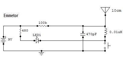
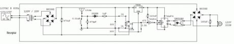
This circuit is a 73 MHz Hallogene Lamp Radio-Controlled. The purpose of it is to control the power state of a hallogene lamp by a remote control. When we press the push botton of the remonte control, the power state of the lamp will be changed, so, if the lamp was turned on, it will turned off and if it was turned on, it will turned off. If we press to the button another time, the same action will be occured. When the button is pressed, a LED indicator lights on the remote control.The system is consisted by two separate circuit. One is the remote control, or the emmetor. The other is the receptor, or the hallogene lamp controller. We plug the input of the lamp controller circuit to the 120VAC source of the sector to supply it. The lamp must be pluged to the output of the circuit to be supplied and controlled.The controller circuit has also an antenna to receive the signal of the remote control. The remote control has also an antenna to transmit the signal to the controller circuit and have to be powered by a 9V battery. Two things important for my circuit are not mentioned in the schematic. There are about the two logic component.The first one is the Schmitt trigger NOT gate (74LS14). Its Vcc pin must be connected to the output of the +5V regulator (7805). And its GND pin must be connected to the ground of the circuit. The second one is the JK Flip-Flop (74LS76). Its Vcc pin must be connected to the output of the +5V regulator (7805). And its GND pin must be connected to the ground of the circuit. (View)
View full Circuit Diagram | Comments | Reading(1031)
Unipolar Stepper Motor Controller
Published:2013/7/29 20:17:00 Author:muriel | Keyword: Unipolar Stepper , Motor Controller
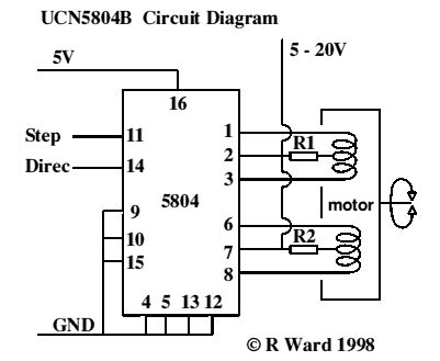
This is a very good integrated circuit. There is no need for any external glue logic to drive the circuit, there is only 2 pins to drive the motor, one for controlling the direction and the other to trigger the stepping pulses. It provides a very compact design that drives 5 or 6 or 8 wire stepper motors. The 5 or 8 wire stepper motors are treated as a variation on the 6 wire motor. That is, the 5 has the two common wires from the coils center taps joined inside the motor (saves joining them outside the motor), however some confusion may occur with the ends of the other coils as to which joins with which, however trial and error to determine this will not hurt anything. In the 8 wire motor case the joined center taps will have to worked out by you. You will know which coil is joined to which coil, however experimentation may be required to determine polarity.
The resistors R1 & R2 are only necessary if the supply voltage to the motors is above 10 volts or so, and are really only necessary near max voltages and tuning the response times of the motor for high speeds. See data sheets for details.There should be very little problem getting hold of six wire motors that make the connections obvious. These motors are by far the most common where any degree of power is required, e.g. in printers. Non-working dot matrix printers are fairly common now-a-days and the motors in them are excellent starting points for experimentation. You will also get belts, pulleys and gears thrown in (may be even a power supply if your are adventurous).
A very simple Printed Circuit Board Design
Features of the chip:1.5A Maximum Output Current35 V Output Sustaining voltageWave-Drive, Two-Phase, and Half Step FormatsInternal Clamp DiodesOutput enable controlPower on resetInternal Thermal ShutdownSequence ConnectionsTwo-Phase Drive Sequence Pin 9 GND Pin 10 GND (Simplest choice)Wave Drive Sequence Pin 9 5v Pin 10 GNDHalf Step Drive Sequence Pin 9 GND Pin 10 5VThis driver will allow you to scale up your project considerably as the power will be much greater with the bigger motors and higher voltages and currents. The draw back is that the engineering that goes along with them will also have to be more substantial. The larger stepper motors are very heavy for desktop models but will be very versatile for the larger experiment.
Commercial Kit and Data SheetsAn excellent, high quality kit (Nos:109) to experiment with this driver can be purchased fromWiltronics Research PTY LTD5-7 Ripon St (North)Ballarat 3350AUSTRALIAPhone (03)5331 1947It provides a 5 volt regulated supply, indicator LEDs, 555 oscillator for pulses and miniature switches to control direction and stepping modes. Single step or free funning can be chosen as well full data sheets provided. They also provide data sheets with the circuit. Contact them for prices. While not the cheapest way to go it is the best seen so far. (View)
View full Circuit Diagram | Comments | Reading(2080)
Fancontrol
Published:2013/7/29 20:16:00 Author:muriel | Keyword: Fancontrol
This is a simple circuit that will do what you want I believe.
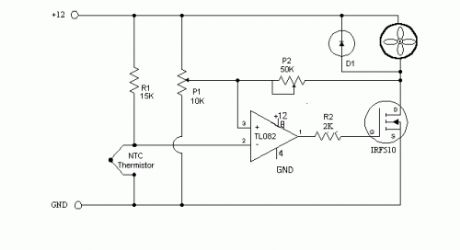
R1 15k ohm resistorNTC Thermistor- 10k ohm, sold at Radio Shack in the states.P1 10k ohm potentiometer - sets the low speed(voltage) of the fans at the cool temperature. P2 50K ohm potentiometer - sets the gain of the circuit - how fast the voltage will rise to full output when the temp is higher. TL082 a op-amp that I had handy, most any single voltage op-amp should work. The TL082 is a dual op-amp if you want more then one controller on a board. note that the power and ground connections for the op-amp are not shown on the schematic. R2 - The TL082 is a fast op-amp, needed R2 to reduce oscillation. IRF-510 A 4 amp mos-fet in a TO-220 case. Bascially as the voltage on the gate rises the mos-fet will conduct more current. note 1 there are also IRF-520 and 530 versions that will handle more current. note 2 Even at 5 watts the mos-fet will disapate some heat and will need to be heat-sinked or at least in the air flow path. the large metal part of the fet will be at drain(D) voltage level. Do not attach to case. D1, almost any diode, 1N4001 should work,it conducts back around the fan when the mos-fet turns off. As the fan continues spinning it will produce a voltage on the drain lead of the fet. D1 will limit that voltage. Adjustment, easiest if you have a voltmeter but can be done without. Get the thermistor at room temp. Adjust P1 for the low speed that you want your fans to run at. Heat the thermistor to the high temp you want the fans at full speed. ( I stuck it under my tongue) Adjust P2 until the fans are at full speed( with voltmeter the highest voltage you can get) then adjust P2 until the speed/voltage just begins to drop off. Most fan specs that I have seen show a low voltage limit of around 7 volts. Some of the smaller 80mm fans have a lower limit of 8 volts. If you set the low voltage to low the fans may stall until the thermistor heats up enough. Let me know if you build this circuit and how it works for you. corrected, single voltage op-amps should be used, OP-07 is a dual voltage. (View)
View full Circuit Diagram | Comments | Reading(1398)
DC Motor Control Circuits
Published:2013/7/29 20:12:00 Author:muriel | Keyword: DC Motor Control Circuits
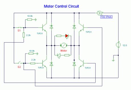
Notes:Here, S1 and S2 are normally open , push to close, press button switches. The diodes can be red or green and are there only to indicate direction. You may need to alter the TIP31 transistors depending on the motor being used. Remember, running under load draws more current. This circuit was built to operate a small motor used for opening and closing a pair of curtains. As an advantage over automatic closing and opening systems, you have control of how much, or how little light to let into a room. The four diodes surriunding the motor, are back EMF diodes. They are chosen to suit the motor. For a 12V motor drawing 1amp under load, I use 1N4001 diodes. (View)
View full Circuit Diagram | Comments | Reading(1146)
Plants Watering Watcher
Published:2013/7/29 20:10:00 Author:muriel | Keyword: Plants Watering Watcher
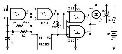
Parts:R1 470K 1/4W ResistorR2 3K3 1/4W ResistorR3 100K 1/2W Trimmer CermetC1 1nF 63V Polyester CapacitorC2 47µF 25V Electrolytic CapacitorD1 1N4148 75V 150mA DiodeD2 5mm. Red LEDIC1 4093 Quad 2 input Schmitt NAND Gate ICP1,P2 Probes (See text)SW1 SPST Slider SwitchB1 3V Battery (2 AA 1.5V Cells in series)
Device purpose:This circuit is intended to signal when a plant is needing water. A LED illuminates at maximum brightness when the ground in the flower-pot is too dry: it dims gradually as the water's content in the pot grows, turning off when the optimum moisture's level is reached. This condition is obtained trimming R3.
Circuit operation:IC1D forms a square wave oscillator with approx. 10/90 mark-space ratio. It feeds the output probe P1 and its signal, inverted by IC1A is compared with that picked-up by P2 in the NAND gates IC1B & IC1C in parallel, driving the LED. When a low resistance exists between the probes, due to an high water's content in the flower-pot, the LED is off, turning gradually on as the resistance between the probes increases.
Notes:A square wave is used to avoid probes' oxidization.Probes can be long nails, carbon rods obtained from disassembled exhausted 1.5V batteries, or even a couple of screwdrivers.The probes must be driven in the pot's ground a few inches apart.Due to 3V supply, the LED needs not a limiting resistor.Power consumption: LED off = 50µA; LED full on = 1mA.To switch-off the circuit, you can short the probes. In this case SW1 can be omitted.Using an high-efficiency LED, brightness variations are better emphasized. In this case a limiting resistor could be necessary. (View)
View full Circuit Diagram | Comments | Reading(1152)
| Pages:8/312 1234567891011121314151617181920Under 20 |
Circuit Categories
power supply circuit
Amplifier Circuit
Basic Circuit
LED and Light Circuit
Sensor Circuit
Signal Processing
Electrical Equipment Circuit
Control Circuit
Remote Control Circuit
A/D-D/A Converter Circuit
Audio Circuit
Measuring and Test Circuit
Communication Circuit
Computer-Related Circuit
555 Circuit
Automotive Circuit
Repairing Circuit