
Control Circuit
Index 12
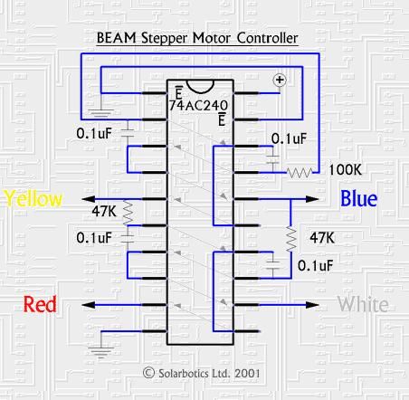
A 74*240-based motor driver
Published:2013/6/27 21:16:00 Author:muriel | Keyword: 74*240-based, motor driver
View full Circuit Diagram | Comments | Reading(826)
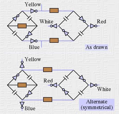
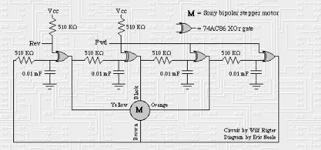
The "BEAM Stepper" drive circuit
Published:2013/6/27 21:12:00 Author:muriel | Keyword: The "BEAM Stepper" , drive circuit
View full Circuit Diagram | Comments | Reading(1005)
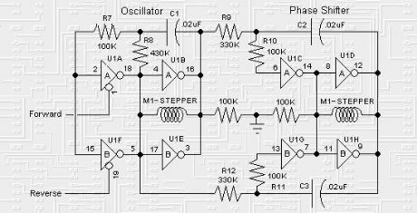
stepper motor drive circuit 2
Published:2013/6/27 21:11:00 Author:muriel | Keyword: stepper motor, drive circuit
View full Circuit Diagram | Comments | Reading(809)
stepper motor drive circuit 1
Published:2013/6/27 21:10:00 Author:muriel | Keyword: stepper motor, drive circuit
View full Circuit Diagram | Comments | Reading(908)
stepper motor drive circuit
Published:2013/6/27 21:09:00 Author:muriel | Keyword: stepper motor , drive circuit
View full Circuit Diagram | Comments | Reading(1077)
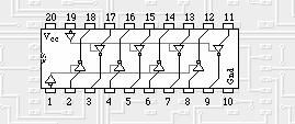
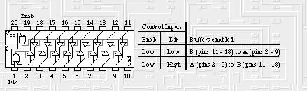
74*245-based motor driver
Published:2013/6/27 21:08:00 Author:muriel | Keyword: 74*245-based , motor driver
View full Circuit Diagram | Comments | Reading(892)
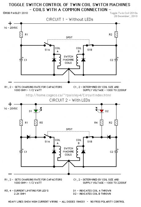
Switch Machines
Published:2013/6/27 20:54:00 Author:muriel | Keyword: Switch Machines
View full Circuit Diagram | Comments | Reading(854)
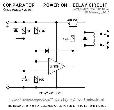
Comparator Power-On Delay Circuits
Published:2013/6/25 22:35:00 Author:muriel | Keyword: Comparator Power-On Delay Circuits
View full Circuit Diagram | Comments | Reading(2179)
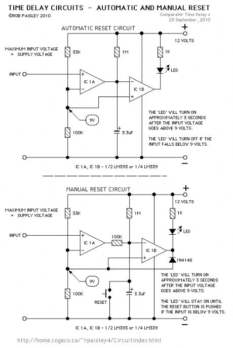
Comparator Timer Delay Schematic #3
Published:2013/6/25 22:34:00 Author:muriel | Keyword: Comparator Timer Delay Schematic
View full Circuit Diagram | Comments | Reading(0)
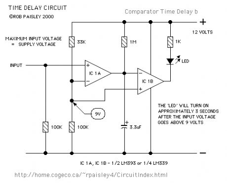
Comparator Timer Delay Schematic #2
Published:2013/6/25 22:33:00 Author:muriel | Keyword: Comparator Timer Delay Schematic
View full Circuit Diagram | Comments | Reading(0)
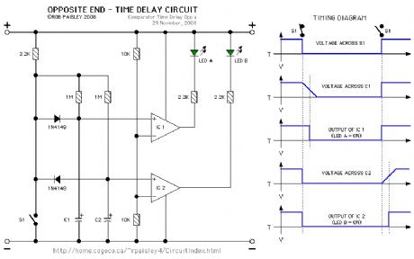
Comparator Time Delay Schematic #1
Published:2013/6/25 22:33:00 Author:muriel | Keyword: Comparator Time Delay Schematic
View full Circuit Diagram | Comments | Reading(0)
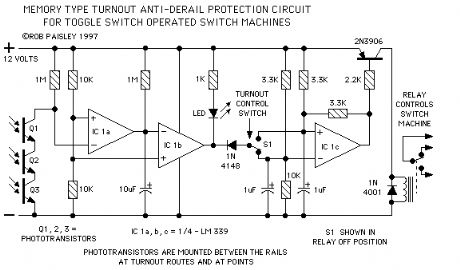
Toggle Switch Type Protection Circuit Schematic
Published:2013/6/25 21:49:00 Author:muriel | Keyword: Toggle Switch Type, Protection Circuit Schematic
View full Circuit Diagram | Comments | Reading(873)
Protection Circuit with SCR Output Schematic
Published:2013/6/25 21:48:00 Author:muriel | Keyword: Protection Circuit , SCR Output Schematic
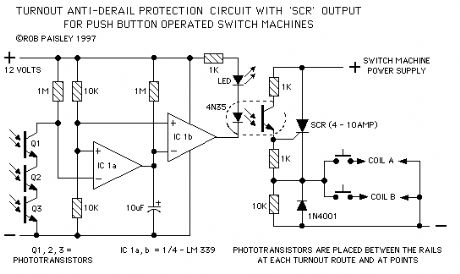
View full Circuit Diagram | Comments | Reading(1997)
Push Button Type Protection Circuit Schematic with Relay Output
Published:2013/6/25 21:48:00 Author:muriel | Keyword: Push Button Type , Protection Circuit Schematic , Relay Output

View full Circuit Diagram | Comments | Reading(1028)
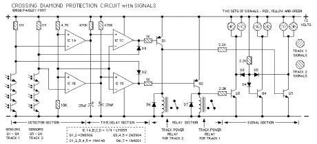
L.M.R.G. Diamond Protection Circuit
Published:2013/6/25 21:47:00 Author:muriel | Keyword: L.M.R.G. Diamond, Protection Circuit
View full Circuit Diagram | Comments | Reading(1022)
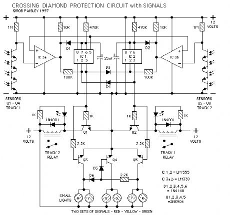
Rail Crossing Diamond Protection Circuit Schematic
Published:2013/6/25 21:46:00 Author:muriel | Keyword: Rail Crossing Diamond , Protection Circuit Schematic
View full Circuit Diagram | Comments | Reading(1131)
Synchronous Flasher Control Schematic
Published:2013/6/25 21:42:00 Author:muriel | Keyword: Synchronous Flasher Control Schematic
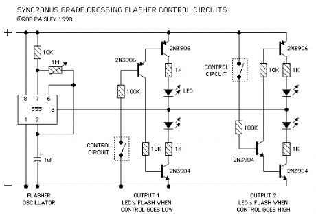
In the synchronous flasher control the oscillator is running at all times and the power to each set of flashers is turned on or off by the control circuit for that crossing. This allows any number of flasher sets at different crossings to controlled individually and yet flash in unison.
Two versions of the flasher output control are shown.
In OUTPUT 1 the lights are turned on when the control circuit goes to the common of the circuit.
In OUTPUT 2 the lights are turned on when the control circuit goes to the positive supply of the circuit or some other supply source.
In either case the PNP and NPN transistors above and below the LED's are turned on and the crossing lights will flash.
IF more than one set of flashers is used at a particular crossing the LED's could be wired in series so as to keep the number of output control circuits to a minimum. This is shown on the basic flasher schematic. (View)
View full Circuit Diagram | Comments | Reading(1142)
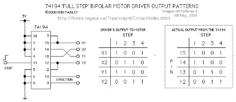
Basic Stepper Motor Driver
Published:2013/6/21 3:12:00 Author:muriel | Keyword: Basic Stepper Motor Driver
View full Circuit Diagram | Comments | Reading(1130)
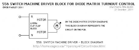
Typical 556 Stall-Motor Driver schematic
Published:2013/6/21 3:06:00 Author:muriel | Keyword: 556 , Stall-Motor, Driver schematic
View full Circuit Diagram | Comments | Reading(899)
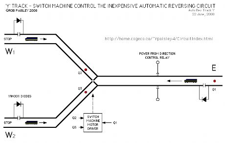
'Y' TRACK SWITCH MACHINE CONTROL
Published:2013/6/21 3:02:00 Author:muriel | Keyword: 'Y' TRACK SWITCH, MACHINE CONTROL
View full Circuit Diagram | Comments | Reading(0)
| Pages:12/312 1234567891011121314151617181920Under 20 |
Circuit Categories
power supply circuit
Amplifier Circuit
Basic Circuit
LED and Light Circuit
Sensor Circuit
Signal Processing
Electrical Equipment Circuit
Control Circuit
Remote Control Circuit
A/D-D/A Converter Circuit
Audio Circuit
Measuring and Test Circuit
Communication Circuit
Computer-Related Circuit
555 Circuit
Automotive Circuit
Repairing Circuit