
Control Circuit
Index 2
With TWH9205 photoelectric coupling type zero control socket circuit diagram
Published:2014/3/13 23:01:00 Author:lynne | Keyword: With TWH9205 photoelectric coupling type zero control socket circuit diagram,
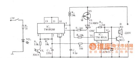
Circuit is shown, which includes zero-drive switch, the optical coupler type input circuit, a control circuit and the thyristor circuit audible sound. FIG phototransistor switch circuit connected to the inverting input terminal of the differential switch TWH9205 amplifier (9 feet), when the terminal voltage is lower than the inverting input terminal of the clamping voltage, that is, when irradiated with light photocell 3DU5, TWH9205 AC output high zero crossing before driving thyristor VS and conduction, XS was electric socket, electrical equipment and XS link into operation. VS according to the size of the electrical load power, the choice of triac 1 ~ 500A. (View)
View full Circuit Diagram | Comments | Reading(1504)
Undervoltage alarm circuit diagram
Published:2014/3/13 22:58:00 Author:lynne | Keyword: Undervoltage alarm circuit diagram,
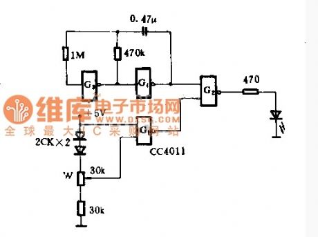
This circuit is a low-pressure alarm circuit 5V power supply, only one and not gate CC4011, with LED indication. Circuit is simple, reliable, low-power consumption. Supply voltage is high enough, G1 output low, G2 output high, light-emitting diodes. When the supply voltage drops to the set value, an input terminal of the G3 becomes a low voltage, high output G1. Thus, the pulse oscillator G3, G4 composition produced by the light emitting diode G2 flash frequency of the oscillator frequency, three times per second.When mediation, just need power plus the minimum allowable value (eg 4V), then change the position of the potentiometer arm, so that the output of G1 can just flip.
(View)
View full Circuit Diagram | Comments | Reading(1853)
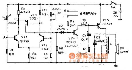
LD168 audio voltage-controlled flash decoration control circuit diagram
Published:2014/3/10 21:47:00 Author:lynne | Keyword: LD168 audio voltage-controlled flash decoration control circuit diagram, LD168

Figure, LD168 is an indication for ASIC sound level for tape recorders flash speakers. It has four outputs can directly drive a plurality of light emitting diodes, thyristor devices can also be driven by the drive lantern light. (View)
View full Circuit Diagram | Comments | Reading(1605)
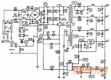
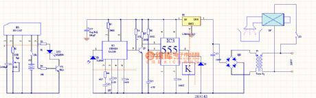
BBK switching power supply diagram
Published:2014/3/10 21:38:00 Author:lynne | Keyword: BBK switching power supply diagram,
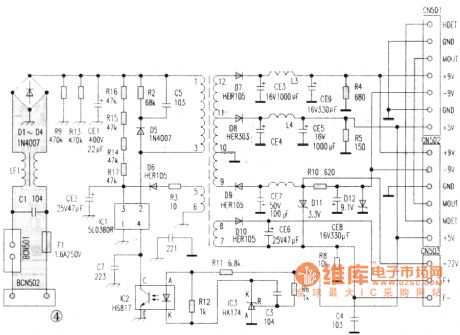
BBK switching power supply diagram shown as figure:
(View)
View full Circuit Diagram | Comments | Reading(2043)
Sound and light dual control electric appliance switches and sockets circuit diagram
Published:2014/3/4 20:15:00 Author:lynne | Keyword: Sound and light dual control electric appliance switches and sockets circuit diagram,
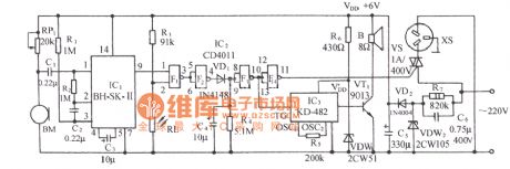
Circuit as shown, it is by the sound transducer sensing switch / electrical, light control switch, thyristor control circuit, vocal music buck rectifier circuit and the AC circuit.
(View)
View full Circuit Diagram | Comments | Reading(1669)
Infrared hood switch controller circuit
Published:2014/3/3 20:20:00 Author:lynne | Keyword: Infrared hood switch controller circuit,
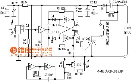
Spend more and more kitchen range hood, it is the kitchen clean and a good helper. We have to press when using the power switch to turn on or off, when we hand full of greasy Would you expect this remarkable line trouble, always made the switch greasy. This circuit is the use of infrared light to control the switch as long as the palm of your hand too close to the switch stays on the line, like infrared faucets, very convenient and practical. Because it is close to using infrared, low power durable, energy-saving.
The circuit is mainly transmitted by infrared, receive, bistable switch and power circuit, as shown . R3, D3, C3 H to the receiving circuit to provide a stable 5V DC voltage. H quiescent current of 1 ~ 2mA. N4, N5 oscillation signal 32KHz , as amended by Q zoom out by the infrared emission tube D7. H receives the signal , high output, amplified by the C4 is coupled to N1 , N1 reverse output low, the flip -flop circuit , N3 high output, triac , exhaust fan work . If the received infrared signal H again , N2, N3 again flipped off SCR, hoods stopped . C5 N1 from interference and stable input level role , R4 is a pull-down resistor .Commissioning of high quality circuit board assembly , according to map production to succeed. Circuit board mounted on the wall switch in the original box . In the switch box cover drill two holes, hole distance of 2 cm, mounted at one end of the D7 sealed cylindrical hollow tube ( available toothpaste cap ), the translucent spout toward the hole, put another hole at the reception circuit H. After making a good integrated infrared transmitter and receiver tubes placed parallel to H ( H bald face and bald face parallel D7 ), internal definitely not light. Adjust the hand away from the D7 W about 15 to 20 cm can flip the circuit . (View)
View full Circuit Diagram | Comments | Reading(1943)
Doppler automatic electronic switch circuit diagram
Published:2014/3/2 21:51:00 Author:lynne | Keyword: Doppler automatic electronic switch circuit diagram,
Resistor R7 is a weak positive feedback resistor every level, so that the high level once the pin ⑧, ⑧ pin so that the high voltage input of the voltage-inverting IC1d rises, causing the pin voltage rises IC1A ③, ① pin voltage rises , ⑦ pin voltage becomes lower, increasing the pulse width of the negative pin ⑦, so C6 sufficient charging time, the lamp is delayed to ensure consistency off.
(View)
View full Circuit Diagram | Comments | Reading(1914)
An economy based on conventional devices PIR switch circuit diagram
Published:2014/2/27 20:21:00 Author:lynne | Keyword: An economy based on conventional devices PIR switch circuit diagram,
An economy based on conventional devices PIR switch circuit diagram shown in Fig.:
(View)
View full Circuit Diagram | Comments | Reading(2179)
Made of SS0001 human pyroelectric voice alarm circuit diagram
Published:2014/2/27 21:02:00 Author:lynne | Keyword: Made of SS0001 human pyroelectric voice alarm circuit diagram,
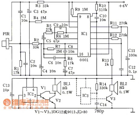
Made of SS0001 human pyroelectric voice alarm circuit diagram as shown:
Pyroelectric infrared language warning device described in this article can be used to prevent electric shock or theft, after a little modification can also be used for automatic light switches. Due to the integrated circuit-based, only a small number of external components, it is easy to install, reliable, almost without debugging, as long as the assembly is correct, will be able to work properly. (View)
View full Circuit Diagram | Comments | Reading(1252)
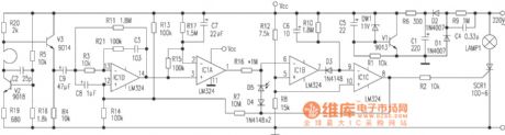
Based on the passive LM324 human body infrared sensor switch circuit
Published:2014/2/26 20:48:00 Author:lynne | Keyword: Based on the passive LM324 human body infrared sensor switch circuit,
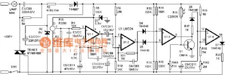
Infrared alarm switch using the most popular PIR human pyroelectric sensor for signal detector, high sensitivity, detection range up to 10 meters above its depression angles up to 86 °, horizontal viewing angle up to 120 °. It is only due to the release of the body, the specific wavelengths of infrared light sensitive, and thus erroneous operation minimal.
When someone with 0.3 ~ 3Hz frequency activity, PIR sensor can be induced in weak signal in the detection area by U1-1, U1-2 levels amplified from U1 (7) output of 0.5 to 5.5 feet V strong signal. D4, D5, R12 ~ R15 and U1-3 consisting of dual-threshold comparator, because the signal voltage induced PIR can be positive or negative, so U1 (7) pin output voltage can be positive or negative (in terms of the center voltage of 3V ). When the output voltage reaches 4.1V or more, through D4 applied to U1 (10) pin voltage is higher than (9) pin voltage (3.3V), so U1 (8) pin output high potential; And when U1 (7 ) when the pin output is below potential 2V, then U1 (voltage 9) pin will drop to 2.7V or less through D2, U1 (8) feet high potential output. Usually when there is no signal, because U1 (9) feet above the potential 3.3V (10) feet (2.7V), so (8) feet no output. When the PIR signal is received (8) feet on certain high potential output through D6, R17 to C9 charge, so U1 (12) feet higher than the potential (13) feet, which (14) feet high potential trigger bidirectional output thyristor conduction, lit the lamp. The stored energy due C8 through R19, RW2 discharge takes about two minutes, so within this 2 minutes light stays lit. When the voltage is lower than C9 (13) pin voltage (1V), the (14) feet no output, SCR turn off lights automatically turn off. CDS photoresistor composition and light control circuit transistor Q1, etc., during the day due to a small photosensitive resistor (10KΩ or less), the transistor Q1 saturated conduction, the U1 (8) feet clamped to about 0.3V, so regardless of whether the induction signal, SCR can not be turned on, the lamp can not be lit; night, due to larger photosensitive resistor to a few megohms, the transistor Q1 is turned off, U1 (8) feet no longer subject to the clamp, once receiving PIR signal, (8) feet immediately output high, the thyristor, the lamp is lit. (View)
View full Circuit Diagram | Comments | Reading(6017)
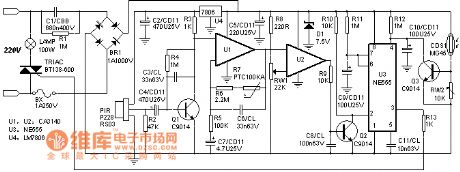
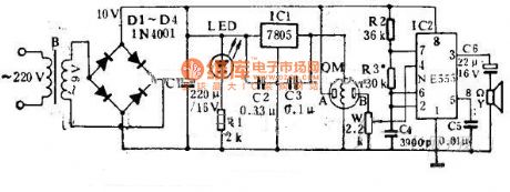
LM324 manufactured using low-cost PIR switch circuit diagram
Published:2014/2/26 20:43:00 Author:lynne | Keyword: LM324 manufactured using low-cost PIR switch circuit diagram,
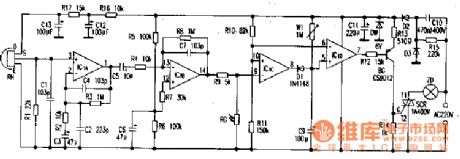
LM324 manufactured using low-cost PIR switch circuit diagram shown in Fig.:
Human pyroelectric infrared detection portion , mainly by the Fresnel lens and pyroelectric infrared sensors, four operational amplifier (LM324) and other components. When the range of the human body into the sensor monitoring , infrared energy lens focused into the low- pass amplifier noninverting IClA , C1, C2, C4 is a high frequency filter capacitor , C3 , and C5 infrared channel low-frequency AC signal . ICIB for the inverting amplifier by R5, R6 and the partial pressure of the noninverting terminal of the bias IClB 1 / 2 Supply voltage to amplify the AC signal , C7 is a high frequency filter capacitor, the two amplifier R3, R2, R8 , R4 determine the amplification gain . IClC composition comparator , ⑩ feet, through R10, R11 divider setting a reference voltage of about 3.9V , the reference voltage is also at the same time as the delay circuit IClD monostable trigger threshold level , 1CIC the comparison voltage signal ⑨ pin , in the photosensitive resistor RG acquired by IClB output through R9 , daytime RG by light , resistance ≤ 10kΩ, IClB high signal output by R9, RG partial pressure is still lower than IClC noninverting terminal level , IClC high power output flat , D1 reverse bias cut . IClD monostable circuit without trigger signal output high , SCR are off, the lamp is not lit . RG no light at night , its resistance ≥ 1MΩ, so IClC output low , D1 is turned on C9 discharges , IClD output low, the lamp is powered light. In the human left , ⑧ feet and high recovery , D1 and off, the power of C9 recharged by W1 , by the delay , when the voltage is higher than C9 ⑥ foot 3.9V, and a single flip -flop circuit IClD output high , lights off. Triac drive circuit triggered by BG SCR, can trigger more reliable. (View)
View full Circuit Diagram | Comments | Reading(10442)
Damp, cool alarm circuit
Published:2014/2/24 20:23:00 Author:lynne | Keyword: Damp, cool alarm circuit,
Damp, cool alarm circuit shown in Figure:
(View)
View full Circuit Diagram | Comments | Reading(1001)
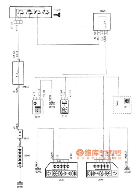
Dongfeng Peugeot Citroen Picasso heating ventilation circuit
Published:2014/2/24 20:23:00 Author:lynne | Keyword: Dongfeng Peugeot Citroen Picasso heating ventilation circuit,
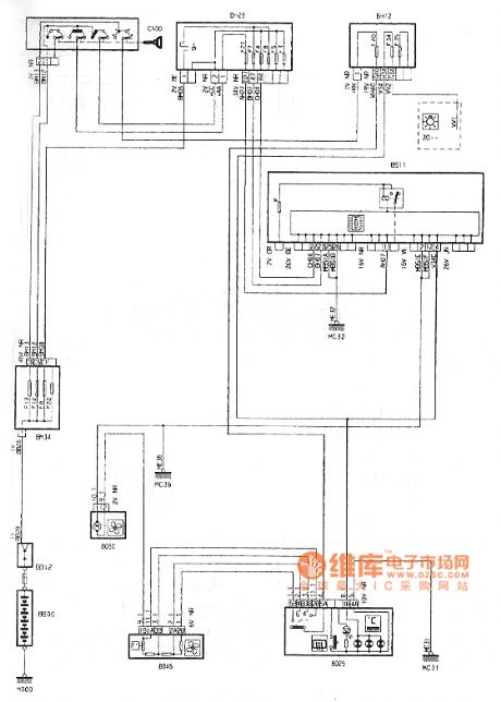
Dongfeng Peugeot Citroen Picasso heating ventilation circuit shown in Figure:
(View)
View full Circuit Diagram | Comments | Reading(1126)
Single-chip infrared sensor controller ZH9576 and application circuit diagram
Published:2014/2/24 20:13:00 Author:lynne | Keyword: Single-chip infrared sensor controller ZH9576 and application circuit diagram,
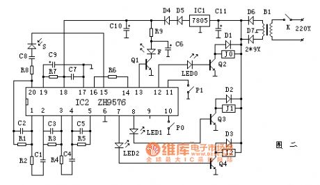
Single-chip infrared sensor controller ZH9576 and application circuit diagram as shown:
(View)
View full Circuit Diagram | Comments | Reading(947)
TYSTAR TY-1412 type SVGA color monitor circuit diagram
Published:2014/2/23 20:54:00 Author:lynne | Keyword: TYSTAR TY-1412 type SVGA color monitor circuit diagram,
TYSTAR TY-1412 type SVGA color monitor circuit diagram shown in Fig.:
(View)
View full Circuit Diagram | Comments | Reading(1076)
Dc motor PWM speed control circuit diagram
Published:2014/2/21 20:10:00 Author:lynne | Keyword: Dc motor PWM speed control circuit diagram,
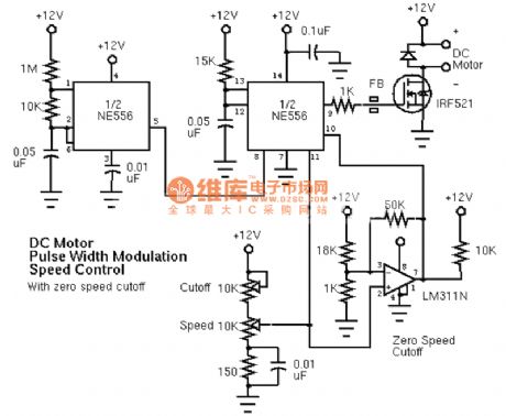
Dc motor PWM speed control circuit diagram as shown:
(View)
View full Circuit Diagram | Comments | Reading(2140)
Fire alarm circuit
Published:2014/2/21 20:01:00 Author:lynne | Keyword: Fire alarm circuit,
Fire alarm circuit shown in Figure:
(View)
View full Circuit Diagram | Comments | Reading(1167)
Two-dimensional lights controller circuit diagram
Published:2014/2/21 19:44:00 Author:lynne | Keyword: Two-dimensional lights controller circuit diagram,
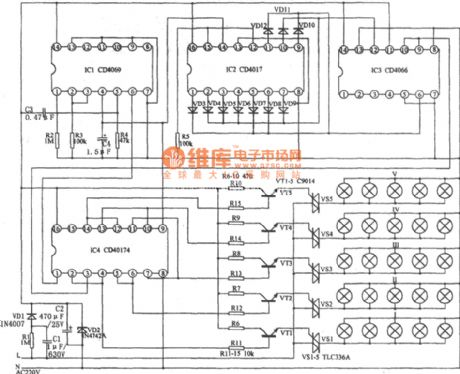
As shown, mainly by the NAND gate IC1 (CD4096), counting / timing distribution circuit IC2 (CD4017), analog electronic switch IC3 (CD4066) and D trigger IC4 (CD40174) and other components. The Lantern Rd controller can control lights lit progressive increments in progressive extinguished. If a combination of a certain number of lights connected, you can create a scene on a flat surface color changes, the color than the usual control flow in a line which is more abundant brilliant. (View)
View full Circuit Diagram | Comments | Reading(1725)
Dongfeng Peugeot Citroen Picasso 2.0L car brake light circuit
Published:2014/2/20 20:37:00 Author:lynne | Keyword: Dongfeng Peugeot Citroen Picasso 2.0L car brake light circuit,
Dongfeng Peugeot Citroen Picasso 2.0L car brake light circuit shown in Figure:
(View)
View full Circuit Diagram | Comments | Reading(1009)
Dispenser automatically switch circuit
Published:2014/2/20 20:21:00 Author:lynne | Keyword: Dispenser automatically switch circuit,
Dispenser automatically switch circuit shown in Figure:
(View)
View full Circuit Diagram | Comments | Reading(1707)
| Pages:2/312 1234567891011121314151617181920Under 20 |
Circuit Categories
power supply circuit
Amplifier Circuit
Basic Circuit
LED and Light Circuit
Sensor Circuit
Signal Processing
Electrical Equipment Circuit
Control Circuit
Remote Control Circuit
A/D-D/A Converter Circuit
Audio Circuit
Measuring and Test Circuit
Communication Circuit
Computer-Related Circuit
555 Circuit
Automotive Circuit
Repairing Circuit