
Control Circuit
Index 14
OpAmp - High Side Current Monitor
Published:2013/6/18 3:45:00 Author:muriel | Keyword: OpAmp , High Side , Current Monitor
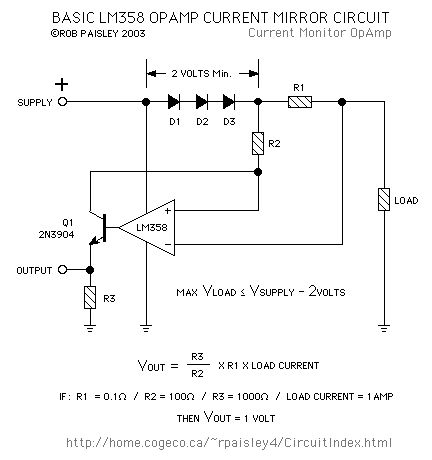
The first circuit is a current monitor made with an LM358 OpAmp. While functional, the three diodes in the supply line make it unsuitable for most applications.
Diodes D1, D2 and D3 are used to ensure that the voltage at the input terminals is at least two volts lower than the amplifiers supply voltage. This is undesirable as the voltage to the load is reduced and power is wasted as heat produced by the diodes.
The circuit is good for experimenting as it can be made from readily available parts. (View)
View full Circuit Diagram | Comments | Reading(2185)
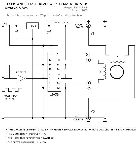
Back And Forth - Bipolar Stepper Motor Driver
Published:2013/6/13 21:19:00 Author:muriel | Keyword: Back And Forth , Bipolar Stepper, Motor Driver
View full Circuit Diagram | Comments | Reading(2773)
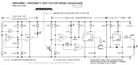
Model Railroad - Infrared Proximity Switch
Published:2013/6/13 21:18:00 Author:muriel | Keyword: Model Railroad , Infrared Proximity Switch
View full Circuit Diagram | Comments | Reading(1335)
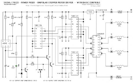
Stepper Motor Driver (74194)
Published:2013/6/13 21:18:00 Author:muriel | Keyword: Stepper Motor Driver , 74194
View full Circuit Diagram | Comments | Reading(3025)
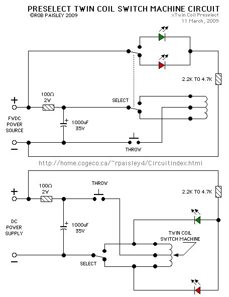
Preselect Twin Coil Switch Machine Circuit
Published:2013/6/13 21:17:00 Author:muriel | Keyword: Preselect Twin Coil, Switch Machine Circuit
View full Circuit Diagram | Comments | Reading(964)
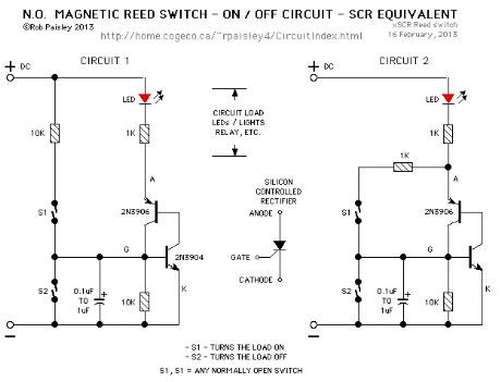
N.O. Magnetic Reed Switch ON /OFF Circuit
Published:2013/6/13 21:16:00 Author:muriel | Keyword: N.O. Magnetic Reed, Switch, ON /OFF Circuit
View full Circuit Diagram | Comments | Reading(1649)
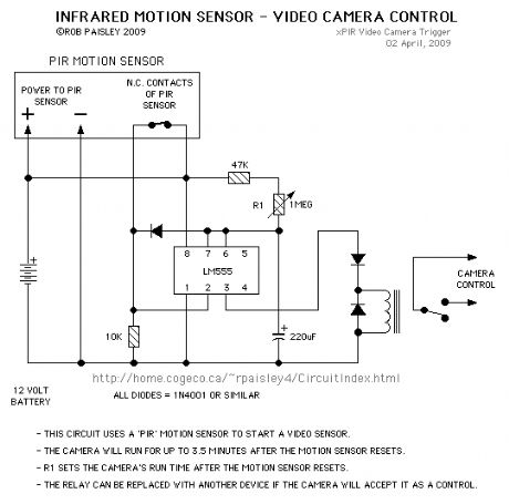
PIR Video Camera Control
Published:2013/6/13 1:43:00 Author:muriel | Keyword: PIR Video Camera Control
View full Circuit Diagram | Comments | Reading(1021)
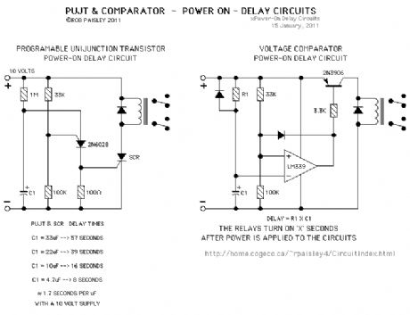
PUJT & Voltage Comparator - Power On - Delay Circuits
Published:2013/6/13 1:42:00 Author:muriel | Keyword: PUJT, Voltage Comparator , Power On - Delay Circuits
View full Circuit Diagram | Comments | Reading(1388)
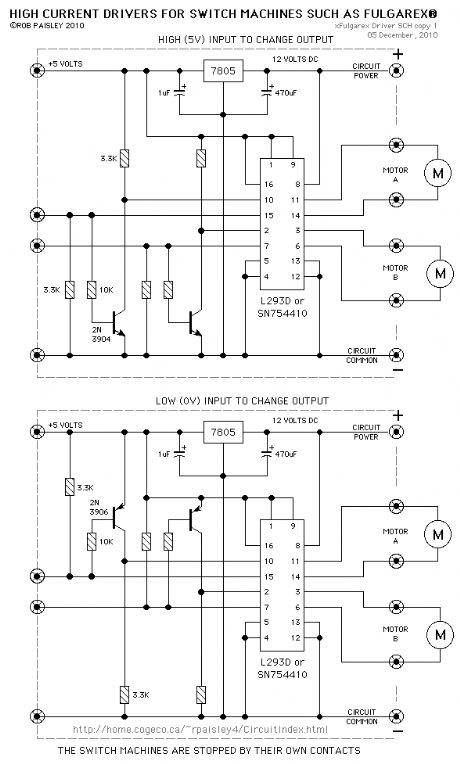
High Current Switch Machine Motor Driver
Published:2013/6/13 1:41:00 Author:muriel | Keyword: High Current, Switch Machine , Motor Driver
View full Circuit Diagram | Comments | Reading(992)
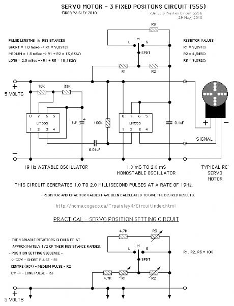
3 Position Servo Driver Circuit (LM555)
Published:2013/6/13 1:41:00 Author:muriel | Keyword: 3 Position , Servo Driver Circuit, LM555
View full Circuit Diagram | Comments | Reading(2030)
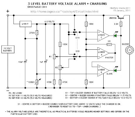
3 Level Battery Voltage Alarm
Published:2013/6/13 1:35:00 Author:muriel | Keyword: 3 Level, Battery , Voltage Alarm
View full Circuit Diagram | Comments | Reading(1004)
H-Bridge Made With A ULN2803 Peripheral Driver
Published:2013/6/13 1:31:00 Author:muriel | Keyword: H-Bridge, ULN2803 , Peripheral Driver
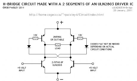
This is not a good design for an (or is it 'a') H-Bridge circuit but it's simple and will work well for low current loads.
The diodes in the base circuit of the PNP transistors might be needed to allow them to cut-off. The resistor in the base circuit depends on the gain of the transistors. A resistor from B+ to the top of the diodes may be needed as well.
The circuit as shown, was tested with a 10 volt supply driving a Tortoise® switch machine with series direction indictating LEDs. (View)
View full Circuit Diagram | Comments | Reading(1589)
DCC Inrush Current Limiter
Published:2013/6/13 1:29:00 Author:muriel | Keyword: DCC, Inrush Current Limiter
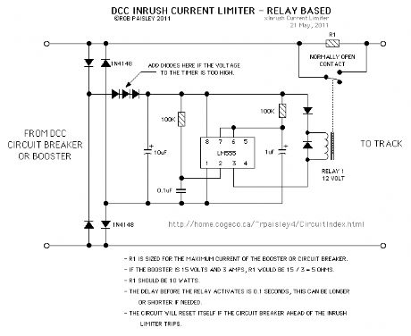
This circuit can be used with DCC boosters and circuit breakers to prevent them from tripping due to a sudden surge of current when power is applied to locomotives with sound cards that have large filter capacitors.
NOTE: This circuit has not been properly tested with sound decoders that have large filter capacitors but should work as intended.
NOTE: It may be possible to use a smaller value for R1.
(View)
View full Circuit Diagram | Comments | Reading(2721)
ULN2003 - High voltage/High Current Peripheral Driver IC
Published:2013/6/7 21:35:00 Author:muriel | Keyword: ULN2003, High voltage, High Current, Peripheral Driver IC
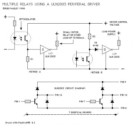
The next diagram shows an inexpensive method of building multiple medium current relays.
The circuit uses a ULN2003 - High voltage/High Current Peripheral Driver IC. This device can handle loads of 500 milliamps.
The IC is designed to have TTL and CMOS inputs of between 5 and 15 volts can be controlled by any clean input voltage. (View)
View full Circuit Diagram | Comments | Reading(1666)
Basic Toy Throttle - Push Button Control
Published:2013/6/7 21:28:00 Author:muriel | Keyword: Basic Toy Throttle , Push Button Control
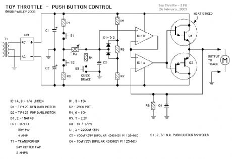
This next circuit is a variation on the Basic Toy throttle. In this version three push buttons are used to control the output.
Button S1 causes the train to move in one direction while S2 moves it in the other. Button S3 is the Quick or emergency brake that will stop the train very quickly.
An interesting feature of this system is that the train could be brought to a stop and then move off in the opposite direction by pressing only one button. Useful for shunting perhaps.
Resistors R5, R6, R7 and diodes D1, D2 form a voltage limiter that reduces the maximum output voltage swing as mentioned in the potentiometer controlled circuit description. (View)
View full Circuit Diagram | Comments | Reading(1253)
Unplugable Walk Around Control and Delayed Reversing Schematic
Published:2013/6/7 21:24:00 Author:muriel | Keyword: Unplugable Walk Around Control , Delayed Reversing Schematic
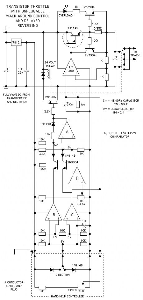
next up is the basic transistor throttle with unplugable walk around control added. The direction memory uses an LM339 quad comparator and has a delayed action so that the direction can not change if the throttle output is above a predetermined voltage.
The delayed reverse section, comparator section D, of the circuit grounds the bases of the transistors whenever the voltage at its PLUS input is higher than the reference voltage at the MINUS input. The PLUS input is connected to the throttle control voltage line.
When the transistor bases are grounded they cannot conduct and any changes at their emitters will have no effect until the control voltage again falls below the preset level.
Comparator sections B and C function as a voltage window detector. That is to say the outputs of both section Band C are high as long as the direction signal voltage is between 4 and 8 volts. If the signal goes below 4 volts or above 8 volts the appropriate output will go low and the direction will change accordingly.
If the controller is unplugged the direction signal will go to 6 volts and the train will maintain its last direction.
Please refer to the voltage comparator information page on this web site for help on how comparators work. (View)
View full Circuit Diagram | Comments | Reading(1142)
Auxiliary Throttle Controls
Published:2013/6/7 21:23:00 Author:muriel | Keyword: Auxiliary Throttle Controls
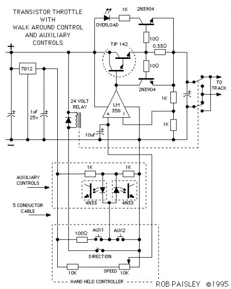
A variation on the walkaround throttle is in the next circuit. If extra wires are added to the control cable they can be put to use for operating accessories on the layout.
For every extra wire 2 such loads can be controlled. Electromagnetic uncoupling ramps could be turned on and off, train whistles could be blown or a reverse loop switch can be thrown after the train has passed.
(View)
View full Circuit Diagram | Comments | Reading(1254)
Walkaround Control for The Basic Throttle
Published:2013/6/7 21:23:00 Author:muriel | Keyword: Walkaround Control , Basic Throttle
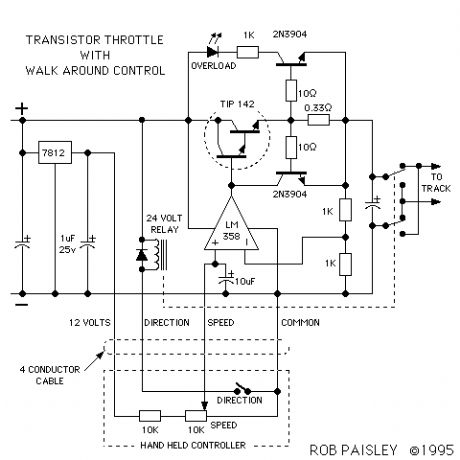
In the next circuit walk around control is added to the throttle. A 4 conductor, 22 Gauge stranded cable will allow the operator to move around with the 'Hand Held Controller' while the power section of the throttle remains at a fixed location.
A DPDT 24 Volt DC relay and a toggle switch has been added for direction control. The direction switch, speed control potentiometer and a 10K ohm resistor are mounted in the Hand Held Controller. (View)
View full Circuit Diagram | Comments | Reading(993)
Simplified Incline Railway Control Circuit Schematic
Published:2013/6/7 21:19:00 Author:muriel | Keyword: Simplified Incline Railway, Control Circuit Schematic
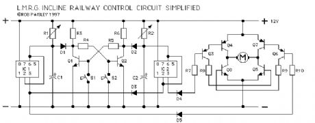
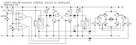
IC 3 is part of the L.M.R.G. circuit and therefore was left in for this article. IC 3 can be omitted from the circuit and the mechanical contacts connected directly of the bases of Q1 and Q2 if desired. This would simplify the circuit but would not change its operation in any way. A schematic of the circuit without IC 3 follows. (View)
View full Circuit Diagram | Comments | Reading(996)
Incline Railway Control Circuit
Published:2013/6/6 21:00:00 Author:muriel | Keyword: Incline Railway, Control Circuit
View full Circuit Diagram | Comments | Reading(1102)
| Pages:14/312 1234567891011121314151617181920Under 20 |
Circuit Categories
power supply circuit
Amplifier Circuit
Basic Circuit
LED and Light Circuit
Sensor Circuit
Signal Processing
Electrical Equipment Circuit
Control Circuit
Remote Control Circuit
A/D-D/A Converter Circuit
Audio Circuit
Measuring and Test Circuit
Communication Circuit
Computer-Related Circuit
555 Circuit
Automotive Circuit
Repairing Circuit