
Control Circuit
Index 19
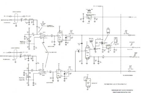
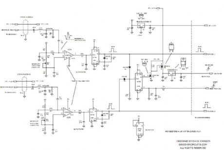
Seismic Alarms
Published:2013/5/14 22:05:00 Author:muriel | Keyword: Seismic Alarms
View full Circuit Diagram | Comments | Reading(1119)
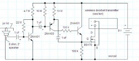
GEOPHONE FOOTSTEP DETECTOR ALARM CIRCUIT
Published:2013/5/14 22:03:00 Author:muriel | Keyword: GEOPHONE FOOTSTEP DETECTOR, ALARM CIRCUIT
View full Circuit Diagram | Comments | Reading(1811)
GEOPHONE FOOTSTEP DETECTOR ALARM CIRCUITS
Published:2013/5/14 21:57:00 Author:muriel | Keyword: GEOPHONE FOOTSTEP DETECTOR , ALARM CIRCUITS
View full Circuit Diagram | Comments | Reading(1868)
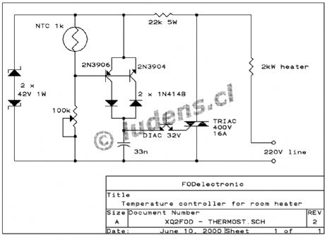
Thermostat for room heater 2
Published:2013/5/9 21:30:00 Author:muriel | Keyword: Thermostat, room heater

View full Circuit Diagram | Comments | Reading(1306)
Plant watering timer 2
Published:2013/5/9 21:30:00 Author:muriel | Keyword: Plant watering timer

View full Circuit Diagram | Comments | Reading(1077)
Photo film processor
Published:2013/5/9 21:28:00 Author:muriel | Keyword: Photo film processor

View full Circuit Diagram | Comments | Reading(1000)
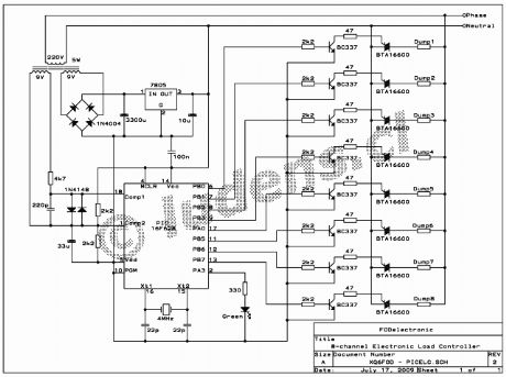
Electronic Load Controller for microhydro system
Published:2013/5/9 21:13:00 Author:muriel | Keyword: Electronic Load Controller, microhydro system
View full Circuit Diagram | Comments | Reading(3251)
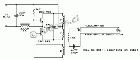
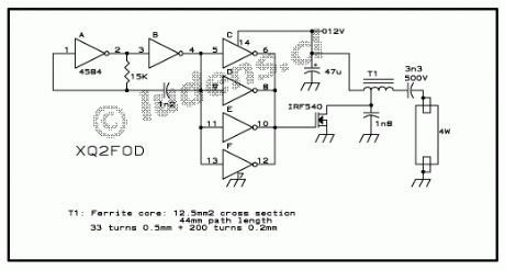
The 8 Watt driver
Published:2013/5/7 22:09:00 Author:muriel | Keyword: The 8 Watt driver
View full Circuit Diagram | Comments | Reading(1471)
The 2 Watt driver
Published:2013/5/7 22:09:00 Author:muriel | Keyword: The 2 Watt driver
View full Circuit Diagram | Comments | Reading(952)
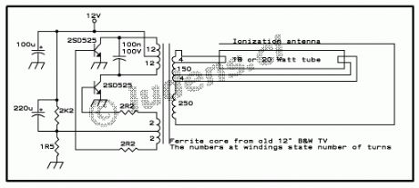
12 Volt Fluorescent Lamp Drivers
Published:2013/5/7 22:08:00 Author:muriel | Keyword: 12 Volt, Fluorescent Lamp Drivers
View full Circuit Diagram | Comments | Reading(1118)
Thermostat for room heater
Published:2013/5/7 22:05:00 Author:muriel | Keyword: Thermostat , room heater
View full Circuit Diagram | Comments | Reading(1235)
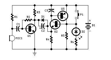
Plant watering timer
Published:2013/5/7 22:03:00 Author:muriel | Keyword: Plant watering timer

If you are like me, you hate doing the same chores every day, all your life. As much as you can automate such things, you should automate them. One of these chores is watering every plant around my apartment, specially those on the balcony! Long ago I made a small gizmo that takes care of this chore. It also keeps the plants alive when I travel away for one or two months.
I simply installed a water hose with a solenoid valve (I used a standard replacement valve for washing machines), and poked thin copper tubes into the hose, leading to each pot. Those plants that require less water get thinner copper tubes. And then I used the following timer circuit to control the valve. Problem solved. The plants are happy. (View)
View full Circuit Diagram | Comments | Reading(1175)
220V MAINS MONITOR
Published:2013/5/7 21:36:00 Author:muriel | Keyword: 220V MAINS MONITOR

View full Circuit Diagram | Comments | Reading(1165)
TELEPHONE LINE MONITOR
Published:2013/5/7 21:31:00 Author:muriel | Keyword: TELEPHONE LINE MONITOR
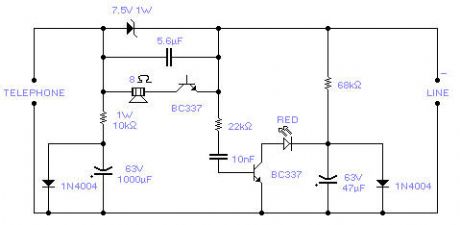
If you feel that somebody is tampering with your telephone line you might find this little circuit useful. It detects if there is another telephone connected to the line, if there is a short or an open line. Sound and a flashing light will tell you which is the current situation. The speaker is practically cut out during a normal conversation thus preserving privacy, only the LED will flash occasionally. The circuit does not require any battery and takes the supply from the telephone line itself. The transistors used are wired in a reversed biased fashion thus behaving as oscillators. You might try the 2N2222A as an alternative (not tested, you may need to increase the zener to 10V for the 2N2222A). This monitor is, of course, suitable only for analogue lines. Watch the polarity of the input line: the circuit will not be damaged by a polarity reversal but it will not operate correctly. (View)
View full Circuit Diagram | Comments | Reading(1785)
LIGHT BULB TIMER
Published:2013/5/7 21:26:00 Author:muriel | Keyword: LIGHT BULB TIMER
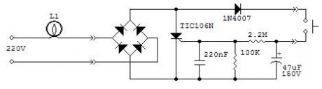
Occasionally you might have a need to keep a light on for a certain time, usually a few minutes, and be sure that it switches off even if you forget to turn off the switch. This could be useful in a cellar or in a closet. The circuit will switch on a light bulb simply by pressing the push button. After a time of 3-7 minutes it will switch off automatically. The long delay is achieved by partly using the leakage current between anode and gate of the scr. This current is dependent almost on anything: voltage, temperature, lamp power, scr device, etc., this is the reason why the timing is not constant but for the intended application it is not important. If the delay is too short you may increase the 220nF capacitor up to 470nF. Too high a value will keep the light always on. It will work with incandescent light bulbs only. Its operation with electronic lamps is erratic and the delay is only 1 or 2 minutes. The scr must be the sensitive gate type and no other type was tested except the TIC106N.
The circuit is rather small and could be housed in the same case as the push button, if there is enough room. Of course you have to substitute the standard switch with a push button. Operation with a 110Vac mains has not been tested although I expect that a 100μF 100V capacitor instead of the 47μF capacitor should do the trick.
It goes without saying that you must know what you are doing as working with the household mains can be dangerous and remember to switch off the mains breaker before doing any work on the electric wiring. Do not attempt to install this circuit if you have doubts on its operation, connections and relevant safety measures. (View)
View full Circuit Diagram | Comments | Reading(1217)
DOMESTIC POWER LIMIT WARNING
Published:2013/5/7 21:26:00 Author:muriel | Keyword: DOMESTIC POWER LIMIT WARNING
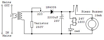
Since a new electricity meter, the electronic variety, was installed at my place, I get cut off if I exceed the set power level, 3.3KWh in my case.
The new meter is unforgiving and although there is a little tolerance built in, you really never know when it has gone over the cut off limit, given the number of electric appliances which are continuously switched on and off.
The circuit was designed to give an audible warning when the 3.3KWh limit is exceeded. The transformer is a disused transformer from a soldering gun. It is relatively easy to remove the few turns of the secondary winding and rewind two turns of thick wire, as thick as the wire coming from the meter at least. One turn should be enough if you have a limit of 6.6KWh, but operation at this power level was not tested. As an alternative you may try a small toroidal mains transformer: it is easy to add a few turns of thick wire. Ignore all other windings, if any, except the primary winding, which in our circuit becomes the secondary winding. The circuit is to be installed between the electricity meter with its breaker and the house wiring. With the given components, the circuit will oscillate at 1 sec. on and 1 sec. off, depending on the load. Adjust the potentiometer so that there is no sound below the power limit. The varistor is necessary in case there is a short in the house wiring: the extra voltage at the secondary may damage the circuit. The piezo buzzer can even be placed away from the circuit in any place where it can be easily heard.
It goes without saying that you must know what you are doing as working with the household mains can be dangerous and remember to switch off the mains breaker before doing any work on the electric wiring. Do not attempt to install this circuit if you have doubts on its operation, connections and relevant safety measures. (View)
View full Circuit Diagram | Comments | Reading(1387)
LONG DELAY TIMER 2
Published:2013/5/7 21:16:00 Author:muriel | Keyword: LONG DELAY TIMER
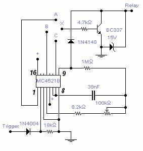
A max. delay of 20 hours is achieved by this relatively simple circuit. A permanent ground, or no signal, at the trigger input starts the timer. A ground at the relay output is available after a set time that depends on the connection of the transistor base (X) to one of the counter output: connection with (C) gives a min. delay of 1m 40s and max. of 18m 30s. Connection with (B) gives a min. delay of 13m 20s and max. of 2h 28m. Connection with (A) gives a min. delay of 1h 47m and max. of 20h. Supply voltage is between 6 and 15V and longer delay could be obtained by increasing the capacitor value up to 10 times with a delay in excess of 1 week. A positive at the trigger input will reset the counter. Adjust the 100K pot. for the desired timing. The load is typically a relay but any load with a max. current of 200 mA will work fine. Admittedly this is not a very original circuit but can save some time if you need to build one. The IC is a Cmos 24-stage binary counter MC4521B from Fairchild, or alternatively, you may use the MC14521B from Motorola. (View)
View full Circuit Diagram | Comments | Reading(1373)
LED or bulb switch off with a puff
Published:2013/5/7 21:05:00 Author:muriel | Keyword: LED or bulb , switch off, a puff
View full Circuit Diagram | Comments | Reading(1306)
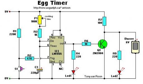
Egg Timer 2
Published:2013/5/7 20:58:00 Author:muriel | Keyword: Egg Timer
View full Circuit Diagram | Comments | Reading(1196)
RS232 Dev Board
Published:2013/5/2 22:35:00 Author:muriel | Keyword: RS232 Dev Board
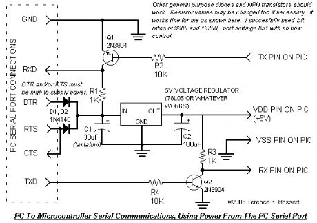
A simple RS232 example project that takes all the power it needs from the serial port. Use it to power your microcontroller and communicate between serial port and microcontroller. Takes advantage of the fact that pc serial ports will accept 0-5V rather than the RS232 standard of around negative 10V to positive 10V. Very convenient – no external power required! Note that you may use either a 5.1V zener or a 5V (View)
View full Circuit Diagram | Comments | Reading(1636)
| Pages:19/312 1234567891011121314151617181920Under 20 |
Circuit Categories
power supply circuit
Amplifier Circuit
Basic Circuit
LED and Light Circuit
Sensor Circuit
Signal Processing
Electrical Equipment Circuit
Control Circuit
Remote Control Circuit
A/D-D/A Converter Circuit
Audio Circuit
Measuring and Test Circuit
Communication Circuit
Computer-Related Circuit
555 Circuit
Automotive Circuit
Repairing Circuit