
Control Circuit
Index 9
Simple DC motor PWN speed control
Published:2013/7/29 20:09:00 Author:muriel | Keyword: Simple DC motor, PWN speed control
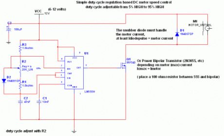
Circuit Explaination:The 555 Ic is wired as an astable and the frequency is constant and independent of the duty cycle, as the total resistance (R charge + R discharge, notice the diode) is constant and equal to 22Kohm (givin a frequency of about 1Khz, notice the hum).When the potentiomenter is all up, the Rcharge resistance is 1,0 Kohm (the diode prevents the capacitor to charge through the second potentiometer section and the other 1,0 Kohm resistor) , and Rdischarge is 21 Kohm, giving a 5% on duty cycle and a 1Khz frequency.When the potentiomenter is all down, the Rcharge resistance is 21,0 Kohm (the diode prevents the capacitor to charge through the second potentiometer section and the other 1,0 Kohm resistor) , and Rdischarge is 1 Kohm, giving a 95% on duty cycle and a 1Khz frequency.When the potentiomenter is at 50% , the Rcharge resistance is 11,0 Kohm (the diode prevents the capacitor to charge through the second potentiometer section and the other 1,0 Kohm resistor) , and Rdischarge is 11 Kohm, giving a 50% on duty cycle and a 1Khz frequency.The 555 provide good current capability to drive the mosfet fast and to drive a bipolar transistor.I actually use this system to drive the DC motor of my small Rotary spark gap Tesla coil at variable speedIf you are disgusted by the 1Khz hum of the motor try to rise the frequency out of the audible range (replacing the potenziometer), but rembember that at higher frequency inductive reactance of motor rises so the the efficiency would drop.
Important:Obviously the mosfet (or bipolar) must have enough current capability to drive the motor, so the drain (or collector) current must be equal to maximum motor current (at power supply voltage, when it is blocked). The snubber diode too, because it shorts the motor on the off cycle. Both mosfet (or bipolar) and diode have to be hooked (if you don't want them cooked ;-) ) to a heatsinkif the max motor current is more than 100 or 200mA. I suggest to not stress to much the motor with too much work because it overheats both motor, transistor and diode.If you don't want braking in the off cycle just place a resistor in series with the snubber diode, it should rise a bit efficiency but have more inertia when slowing the motor down. The value of the resistor must be R=V(breakdown transistor) / Imax, and the power should be 5W. Mosfets have internal zener diode, but don't count on it ;-) (View)
View full Circuit Diagram | Comments | Reading(1521)
Fridge door Alarm circuit
Published:2013/7/29 20:09:00 Author:muriel | Keyword: Fridge door , Alarm circuit
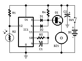
Parts:R1 10K 1/4W ResistorR2 Photo resistor (any type)R3,R4 100K 1/4W ResistorsC1 10nF 63V Polyester CapacitorC2 100µF 25V Electrolytic CapacitorD1,D2 1N4148 75V 150mA DiodesIC1 4060 14 stage ripple counter and oscillator ICQ1 BC337 45V 800mA NPN TransistorBZ1 Piezo sounder (incorporating 3KHz oscillator)SW1 Miniature SPST slide SwitchB1 3V Battery (2 AA 1.5V Cells in series)
Circuit operation:This circuit, enclosed in a small box, is placed in the fridge near the lamp (if any) or the opening. With the door closed the interior of the fridge is in the dark, the photo resistor R2 has a high resistance (>200K) thus clamping IC1 by holding pin 12 high. When a beam of light enters from the opening, or the fridge lamp lights, the photo resistor lowers its resistance (<2K), pin 12 goes low, IC1 starts counting and, after a preset delay (20 seconds in this case) the piezo sounder beeps for 20 sec. then stops for the same lapse of time and the cycle repeats until the fridge door closes. D2 connected to pin 6 of IC1 makes the piezo sounder beeping 3 times per second.
Notes:Connecting D1 to pin 2 of IC1 halves the delay time.Delay time can be varied changing C1 and/or R3 values.Any photo resistor type should work well.Current drawing is insignificant, so SW1 can be eliminated.Place the circuit near the lamp and take it away when defrosting, to avoid circuit damage due to excessive moisture.Don't place it in the freezer. (View)
View full Circuit Diagram | Comments | Reading(1034)
Auto Heat Limiter for Soldering Iron
Published:2013/7/29 20:07:00 Author:muriel | Keyword: Auto Heat Limiter, Soldering Iron
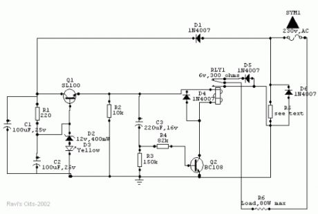
Wattage of load 10W 18W 25W 35W 65W 80WValue of R5 (in ohms) 330 180 136 (68+68) 100 56 44 (22+22)Wattage of R5 (in watts) 01 02 02 04 05 6.5
Usually a soldering iron takes a couple of minutes to get adequately heated up to melt the solder, after which the heat generated is much above the requirement and is wasted. Moreover, excessive heat decreases the life of the bit and the element, causing serious damage to the components.The above circuit solves this problem in a simple and inexpensive way and could be used to various types of loads up to 80watts.
How it worksOnce the main is switched on, an approximate 15v drop of the positive half cycle across R5 is detected and supplied to Q1 (SL100 or D313), which acts as a voltage regulator. Zener diode D2 together with diode D3 (yellow LED) stabilizes the emitter voltage of Q1 at 13.2Vdc, which is then delivered to the relay circuit built around Q2 and C3. Capacitor C3 charges through the base-emitter path of Q2 and causes the relay to actuate, which in turn allows both the half cycles of the AC mains to flow through diode D6 and R5 to the load to heat it up at a normal rate.After a certain lapse of time (about 2 minutes preset) C3 saturates and Q2 stops conducting through the relay, thus switching on series diode D5 to allow only half of the Ac cycle through the load.After switching off the system, C3 discharges very slowly through R2 and R3. Before C3 gets completely discharged, if the power is switched on again, C3 takes a shorter time to reach the saturation level, thus switching series diode D5 much earlier than the preset time to prevent double heating of the load.However, if the circuit is switched on only after a few seconds of switching off, C3 gets no time to discharge and the relay does not actuate at all. Moreover, if the relay circuit fails due to any reason and Q2 does not conduct, no harm is done to the load because in that case D5 remains in series with it. Thus the circuit offers complete protection to the load.As stated earlier, the given value of C3 gives a delay of 2 minutes. However, a 1000mfd capacitor can also be used to produce a 4.5-minute delay. R5 maintains a drop of about 15V across itself. So for use in different load conditions its value changes as shown in Table 1.The whole circuit can be mounted on a PCB and fitted in an adapter case (7.6cm X 5.1cm X 6.4cm) and used as a mains plug. Since R5 gets heated up during the operation, it should be kept well isolated from the other components.
PartsR1 - 220 ohmsR2 – 10KR3 – 150KR4 – 82K(all resistors should be 5% close tolerance)C1- 100 uf, 25V dc working electrolyticC2 – 100 uf, 25V dc working electrolyticC3 – 220 uf, 16V dc working electrolytic(advisable to use close tolerance Caps. to obtain correct timings)D1, D4, D5, & D6 – IN4007D2 – 12V 400mw, Zener diodeD3 – Yellow LEDRLY1 – 6V, 300 ohms DC relayQ1 – SL100 or D313Q2 – BC108 (View)
View full Circuit Diagram | Comments | Reading(2019)
Voice activated switch
Published:2013/7/29 20:06:00 Author:muriel | Keyword: Voice activated switch
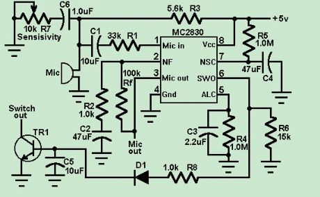
This circuit uses an MC2830 to form a voice activated switch ( VOX ). A traditional VOX circuit is unable to distinguish between voice and noise in the incoming signal. In a noisy environment, the switch is often triggered by noise, or the activation sensitivity must be turned down. This circuit overcomes this weakness. The switch is activated by voice level above the noise and not activated by background noise. This is done by utilizing the differences in voice and noise waveforms. Voice waveforms generally have a wide range of variation in amplitude, whereas noise waveforms are more stable. The sensitivity of the voice activation depends on the value of R6. The voice activation sensitivity is reduced from 3.0dB to 8.0dB above the noise if R6 changes from 14k to 7.0k . (View)
View full Circuit Diagram | Comments | Reading(2650)
Servo Controller
Published:2013/7/29 1:42:00 Author:lynne | Keyword: Servo Controller
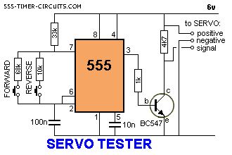
This circuit can be used to manually turn a servo clockwise and anti-clockwise. By pushing the forward or reverse button for a short period of time you can control the rotation of the servo. It will also test a servo. Here is a photo of a kit from Cana Kit for $10.00 plus postage (it is a slightly different circuit) and a motor and gearbox, commonly called a servo. The output shaft has a disk or wheel containing holes. A linkage or push-rod is fitted to a hole and when the disk rotates, the shaft is pushed and pulled. The shaft only rotates about 180� to actuate flaps or ailerons etc.
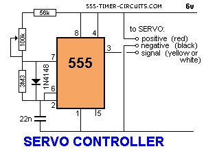
A pot can be used to control the position of the servo by using the following circuit. It produces a positive pulse between about 0.9 milliseconds and 2.1 milliseconds. The off period between pulses is about 40 milliseconds. This can be shortened by reducing the value of the 3M3 resistor. (View)
View full Circuit Diagram | Comments | Reading(1894)
Sound Operated Switches
Published:2013/7/28 20:20:00 Author:muriel | Keyword: Sound Operated Switches
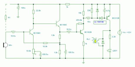
Notes:This sensitive sound operated switch can be used with a dynamic microphone insert as above, or be used with an electret (ECM) microphone. If an ECM is used then R1 (shown dotted) will need to be included. A suitable value would be between 2.2k and 10kohms.The two BC109C transitors form an audio preamp, the gain of which is controlled by the 10k preset. The output is further amplified by a BC182B transistor. To prevent instability the preamp is decoupled with a 100u capacitor and 1k resistor. The audio voltage at the collector of the BC182B is rectified by the two 1N4148 diodes and 4.7u capacitor. This dc voltage willdirectly drive the BC212B transistor and operate the relay and LED.It should be noted that this circuit does not latch . The relay and LED operate momentarily in response to audio peaks. (View)
View full Circuit Diagram | Comments | Reading(988)
On-Off Temperature Control
Published:2013/7/28 20:15:00 Author:muriel | Keyword: On-Off Temperature Control

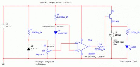
This circuit controls a load (in this case a dc brushless fan) based on a temperature compared with a setpoint. THe transduced is a diode in the forward polarization regime. In fact when forward biased, the forward voltage drop accross a diode has a temperature dependance, in particular has a negative linear(ish) slope. This because of the boltzmann distribuition, causing electrons to pass to the conduction band thermically, lowering the voltage drop accross the diode.Anyway this circuit comparates a precise voltage reference (zener) with the forward voltage drop of the diode forward biased with 11mA of current.The comparator is simply a LM158/258/358 working in open-loop mode, the inverting input is connected to the diode sensor, and the noninverting to the reference voltage. Se when the temperature rises above the setpoint, the forward voltage drops under the voltage reference and the comparator output is vccturning on the transistor and so the fan.Higher power transistor can be substituted for bigger fans, or you can substitute a relay, IGBT, mosfet etc to control higher loads (and higher voltages).The setpoint is adjusted with the potentiometer, and you can use a LM3914 led driver to make a temperature setpoint indicator (needs careful calibrations and the use of excel to calculate slope and intercept).Many modifications can be done, but the circuit works very well in its basic form.THe comparator can distinguish 10uV differences so approx 0.01°C differences (carefully adjusting the potentiometer can allow to feel body heat from 1/2 cm from the sensor, or feel ambient heat, making to turn the fan on and off continuosly)You can control temperatures up to 140°C (150 max diode temperature), but linearity is not ensuredPossible uses? Heatsink cooling, computer emergency cooling (but i thint that a linear device would be better than a on-off) metal cooling when drilling etc...Ah! One note: you can even heat with this circuit but you need the reverse comparator inputs and substitute the fan with a relay controlling the heater. (View)
View full Circuit Diagram | Comments | Reading(1404)
Touch Switch II
Published:2013/7/28 20:13:00 Author:muriel | Keyword: Touch Switch II
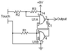
A touch switch is a switch that is turned on and off by touching a wire contact, instead of flicking a lever like a regular switch. Touch switches have no mechanical parts to wear out, so they last a lot longer than regular switches. Touch switches can be used in places where regular switches would not last, such as wet or very dusty areas.
PartsC1 10uF 16V Electrolytic CapacitorR1, R2 100K 1/4 Watt ResistorR3 10 Meg 1/4 Watt ResistorU1 4011 CMOS NAND Gate ICMISC Board, Wire, Socket For U1Notes:1. The contacts an be made with just two loops of wire close together, or two squares etched close together on a PC board.2. When activated, the output of the circuit goes high for about one second. This pulse can be used to drive a relay, transistor, other logic, etc.3. You can vary the length of the output pulse by using a smaller or larger capacitor for C1. (View)
View full Circuit Diagram | Comments | Reading(2174)
IR Remote Control Extender Circuit
Published:2013/7/28 20:11:00 Author:muriel | Keyword: IR Remote Control, Extender Circuit
This is an improved IR remote control extender circuit. It has high noise immunity, is resistant to ambient and reflected light and has an increased range from remote control to the extender circuit of about 7 meters. It should work with any domestic apparatus that use 36-38kHz for the IR carrier frequency. Please note that this is NOT compatible with some satellite receivers that use 115KHz as a carrier frequency.
Notes:The main difference between this version and the previous circuit, is that this design uses a commercially available Infra Red module. This module, part number IR1 is available from Harrison Electronics in the UK. The IR module contains a built in photo diode, amplifier circuit and buffer and decoder. It is centerd on the common 38kHz carrier frequency that most IR controls use. The module removes most of the carrier allowing decoded pulses to pass to the appliance. Domestic TV's and VCR's use extra filtering is used to completely remove the carrier. The IR1 is packaged in a small aluminium case, the connections viewed from underneath are shown below: (View)
View full Circuit Diagram | Comments | Reading(1037)
Everything-that-moves ALARM
Published:2013/7/28 20:10:00 Author:muriel | Keyword: Everything-that-moves ALARM
A crucial failing of proximity detectors is their unreliable and tricky nature. This is where they are used to detect humans, not to speak of smaller living beings. One common approach is to detect eddy currents in a living body, which are induced in the body through a.c. mains wiring. However, such circuits become altogether unusable in the case of mains failure, or in the absence of mains electricity, or even where adjacent mains circuits are switched in and out.
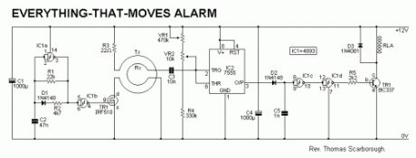
The circuit of Fig.1 takes the guesswork out of proximity detection by inducing eddy currents in a living being, whether animal or human. Five turns of enamelled copper wire (say 30 s.w.g.) are wound around the area within which detection is to take place (4m x 4m in tests), and an audio signal of about ¼ Watt is pulsed through this, the Tx, coil. A smaller Rx coil (say 100 turns of 30 s.w.g. enamelled copper wire wound on a 150mm dia. former) is used as a pick-up coil. The circuit is adjusted by means of tune and fine-tune controls VR1 and VR2, so that it is deactivated when one stands back from the Rx coil.
A simple clock generator (IC1a-IC1b) and power MOSFET (TR1) are used for the transmitter, and a 7555 timer (IC2) is wired as a sine-square convertor for the receiver. IC2's inputs are biased through VR1, VR2 and R4. IC2 in turn switches NAND gates IC1c and IC1d, to drive relay RLA. Capacitor C5 switches the relay for about two seconds, and its value may be increased or decreased to give different timing periods. D2 is critical to prevent back-e.m.f. from re-triggering the circuit. Supply decoupling capacitors C1 and C4 are also critical, and should be located close to IC1 and IC2 respectively.
When a living being - animal or human - comes within tens of centimetres of the Rx coil, the circuit is triggered. This coil may be placed in the threshold of a door, under a carpet, or around a hatch, at the base of a tree, and so on. A number of such coils may also be wired in series.
Coils may be wound with a larger or smaller diameter, with more or less turns, and the power of the transmitter may be varied, as well as the sensitivity of the receiver. Note that a.m. radio reception may be affected at close proximity to the Tx coil. (View)
View full Circuit Diagram | Comments | Reading(1174)
Stepper Motor Controllers
Published:2013/7/28 20:08:00 Author:muriel | Keyword: Stepper Motor Controllers
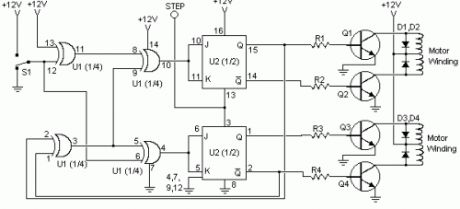
I found this circuit in my files. I don't know where it came from, but it looks like I photocopied it from somewhere years ago. I have been told that it came from The Robot Builder's Bonanza , by Gordan McComb. Anyway, I thought that it should be fairly useful, so I decided to post it here. The circuit is very simple and inexpensive. This is good thing because most commercial stepper motor controller ICs are quite expensive. This circuit is built from standard components and can easily be adapted to be controlled by a computer. If you use cheap surplus transistors and stepper motor, the price of the circuit can be kept to under $10.
I found this circuit in my files. I don't know where it came from, but it looks like I photocopied it from somewhere years ago. I have been told that it came from The Robot Builder's Bonanza , by Gordan McComb. Anyway, I thought that it should be fairly useful, so I decided to post it here. The circuit is very simple and inexpensive. This is good thing because most commercial stepper motor controller ICs are quite expensive. This circuit is built from standard components and can easily be adapted to be controlled by a computer. If you use cheap surplus transistors and stepper motor, the price of the circuit can be kept to under $10. (View)
View full Circuit Diagram | Comments | Reading(1323)
Infrared Remote Control
Published:2013/7/28 20:08:00 Author:muriel | Keyword: Infrared Remote Control
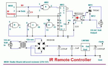
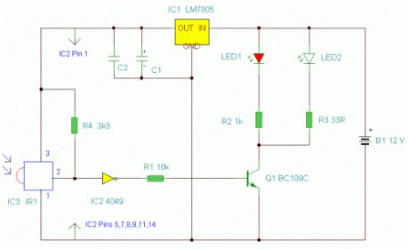
This circuit will allow you to turn on any piece of equipment that operates on 115 volts ac. The reciever circuit is based on the Radio Shack infrared receiver module(MOD), part number 276-137. It is also available from some of the other sources listed on my Links page. The MOD accepts a 40khz IR signal that is modulated at 4 khz. When a signal is recieved the MOD will go low. The sensitivity of the MOD is set by different values for R1 and C1.The values for R1 may need to be as high as 10,000 ohms and for C1 40uf. This will prevent the unit from turning on under normal lighting conditions. You will need to experiment with the vaules that work best for you. The output of the 4013 chip a flip flop toggles on and off with the reception of a IR pulse. The output of the 4013 turns on the MOC optical coupler which in turn switches on the triac and supplies power to the AC load.
(View)
View full Circuit Diagram | Comments | Reading(1264)
Light switch
Published:2013/7/28 20:07:00 Author:muriel | Keyword: Light switch
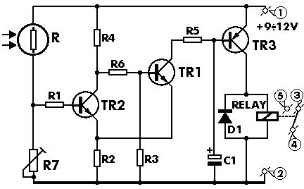
General DescriptionThis project will let you make a switch that will be activated by light falling on a sensor. It is a very useful device and can be used in automatism’s, security systems, counters, remote controls etc. It is very sensitive, fast acting and reliable. The circuit uses a Light Dependent Resistor (LDR) as a sensor and three transistors to amplify the signals from the LDR and drive the relay which does the switching.
Technical Specifications - CharacteristicsWorking voltage: ......... 12 VDCMaximum current: ....... 50 mA
How it WorksAs you can see from the circuit diagram in the input of the circuit there is a trimmer (R7) connected in series with the LDR in such a way as to form a voltage divider. When light falls on the LDR it causes its resistance to change and this causes the voltage across the LDR to change accordingly. These voltage changes are used to change the state of the transistor TR2 switching it ON and OFF. Theoutput from TR2 drives TR1 and this in turn TR3 which drives the output relay. The diode D1 protects the transistor from the back emf that is produced from the relay coil when it is turned off. The trimmer R7 adjusts the sensitivity of the circuit so it is possible to use it under widely different conditions. The circuit operates from a 9-12 VDC power supply and the relay contacts are rated at 250 V/2 A.ConstructionFirst of all let us consider a few basics in building electronic circuits on a printed circuit board. The board is made of a thin insulating material clad with a thin layer of conductive copper that is shaped in such a way as to form the necessary conductors between the various components of the circuit. The use of a properly designed printed circuit board is very desirable as it speeds construction upconsiderably and reduces the possibility of making errors. Smart Kit boards also come pre-drilled and with the outline of the components and their identification printed on the component side to make construction easier.To protect the board during storage from oxidation and assure it gets to you in perfect condition the copper is tinned during manufacturing and covered with a special varnish that protects it from getting oxidised and makes soldering easier.Soldering the components to the board is the only way to build your circuit and from the way you do it depends greatly your success or failure. This work is not very difficult and if you stick to a few rules you should have no problems. The soldering iron that you use must be light and its power should not exceed the 25 Watts. The tip should be fine and must be kept clean at all times. For this purpose come very handy specially made sponges that are kept wet and from time to time you can wipe the hot tip on them to remove all the residues that tend to accumulate on it. DO NOT file or sandpaper a dirty or worn out tip. If the tip can not be cleaned,replace it. There are many different types of solder in the market and you should choose a good quality one that contains the necessary flux in its core, to assure a perfect joint every time. DO NOT use soldering flux apart from that which is already included in your solder. Too much flux can cause many problems and is one of the main causes of circuit malfunction. If nevertheless you have touse extra flux, as it is the case when you have to tin copper wires, clean it very thoroughly after you finish your work. In order to solder a component correctly you should do the following: Clean the component leads with a small piece of emery paper - Bend them at thecorrect distance from the component body and insert the component in its place on the board. You may sometimes find a component with heavier gauge leads than usual, that are too thick to enter in the holes of the p.c. board. In this case use a mini drill toincrease the diameter of the holes slightly. Do not make the holes too large as this is going to make soldering difficult afterwards.Take the hot iron and place its tip on the component lead while holding the end of the solder wire at the point where the lead merges from the board. The iron tip must touch the lead slightly above the p.c. board. When the solder starts to melt and flow wait till it covers evenly the area around the hole and the flux boils and gets out from underneath the solder. The whole operation should not take more than 5 seconds. Remove the iron and leave the solder to cool naturally without blowing on it or moving the component. If everythingwas done properly the surface of the joint must have a bright metallic finish and its edges should be smoothly ended on the component lead and the board track. If the solder looks dull, cracked, or has the shape of a blob then you have made adry joint and you should remove the solder (with a pump, or a solder wick) and redo it. Take care not to overheat the tracks as it is very easy to lift them from the board and break them. When you are soldering a sensitive component it is good practice to hold the lead from the component side of the board with a pair of long-nose pliers to divert any heat that could possibly damage the component.Make sure that you do not use more solder than it is necessary as you are running the risk of short-circuiting adjacent tracks on the board, especially if they are very close together.After finishing your work cut off the excess of the component leads and clean the board thoroughly with a suitable solvent to remove all flux residues that still remain on it. You shouldn’t face any special problems with this project. The only unusual component is the LDR and you should decide where you want to put your project and how you are going to activate it as it will be necessary to leave a hole in the case for the sensor and possibly orientated the whole case towards the light beam. As usual start building the circuit with the resistors leaving the LDR for the final stage. Mount the relay on the board and solder the transistors and the diode in their places making sure that nothing went in the wrong place or the wrong way round. When everything is in its place solder the LDR carefully, as it is very fragile and can be easily damaged if overheated. Make the last visual check and if you are satisfied that all is well you can connect the circuit to a power supply or a battery of at least 9 VDC. Cover the sensitive surface of the LDR and turn the trimmer till you hear the relay clicking. If you uncover the sensor the relay should click again. You will probably have to read just the trimmer once the circuit is cased and you are ready to use it in some application, in order to fine-tune it to the conditions that you want it to operate in.
WarningSmart kits are sold as stand alone training kits. If they are used as part of a larger assembly and any damage is caused, our company bears no responsibility.While using electrical parts, handle power supply and equipment with great care, following safety standards as described by international specs and regulations.
If it does not workCheck the power supply to make sure there are at least 9 VDC across the circuit, and that the polarity is correct. Make sure the transistors and the diode are connected the right way round. Check your work for possible dry joints, bridges across adjacent tracks or soldering flux residues that usually cause problems.
(View)
View full Circuit Diagram | Comments | Reading(1286)
Magnetic-Radiation Remote-Control 1
Published:2013/7/28 20:07:00 Author:muriel | Keyword: Magnetic-Radiation Remote-Control
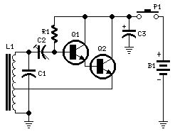
Transmitter parts:R1 68K 1/4W ResistorC1 4n7 630V Ceramic or Polyester CapacitorC2 60-80pF 63V Ceramic TrimmerC3 100µF 25V Electrolytic CapacitorQ1 BC337 45V 800mA NPN TransistorQ2 BD139 80V 1.5A NPN TransistorL1 500 turns on a 10mm. diameter, 10cm. long ferrite rod.Enameled wire diameter: 0.2mm.The tap is made after 200 turns, ground sideP1 SPST PushbuttonB1 6-9V Battery (4 to 6 AA 1.5V Cells in series, see Notes)
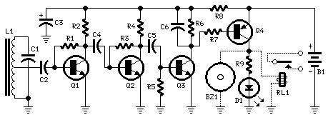
Receiver parts:R1,R3 1M 1/4W ResistorsR2,R4 47K 1/4W ResistorsR5 330K 1/4W ResistorR6,R7 68K 1/4W ResistorsR8 180R 1/4W ResistorR9 100R 1/4W ResistorC1 470pF 63V Ceramic Capacitor (See Notes)C2 10nF 63V Polyester or Ceramic CapacitorC3 100µF 25V Electrolytic CapacitorC4,C5 100nF 63V Polyester or Ceramic CapacitorsC6 1µF 63V Polyester, Ceramic or Electrolytic CapacitorD1 5 or 3mm. Red LEDQ1,Q2,Q3 BC549C 25V 100mA NPN High-gain Low-noise TransistorsQ4 BD328 30V 800mA PNP TransistorL1 700 turns on a 10mm. diameter, 10cm. long ferrite rod.Enameled wire diameter: 0.2mm.The tap is made after 350 turns, i.e. at the center of the windingBZ1 Piezo sounder (incorporating 3KHz oscillator, optional, see Notes)RL1 5V DIL Reed-Relay SPDT or DPDT (Optional, see Notes)B1 3V Battery (2 x 1.5V AA, AAA or AAAA Cells in series or 1 x 3V Lithium Cell)
Device purpose:This unit can be useful as a short-range, single-channel remote-control. When the pushbutton in the transmitter circuit is briefly activated, the LED D1 in the receiver illuminates and an optional beeper or relay can be operated.Circuit operation is based on a non-modulated 35KHz frequency carrier transmitter, and on a high-gain two-stage 35KHz amplifier receiver, followed by a frequency-voltage converter and DC load driver.Outstanding features for this design are as follows:No outer antenna is required on both transmitter and receiver sections, due to the very low frequency operation. The antennas are 10mm. diameter, 10cm. long ferrite rods supporting the coils.Unlike Infra-red remote-controls, this unit operates through the walls etc.No radio-frequency interference in spite of simple circuitry.The receiver operates at ultra-low voltage supply (3V) and standing current (100µA): in this manner it can be left in stand-by mode for years before a battery replacement is needed. Snags are: the short-range operation (about a medium-sized apartment), the high number of windings for the coils and the high current drawn by the transmitter.Luckily, this latter snag is compensated by the fact that only a short pulse from the transmitter is needed to operate the receiver. Therefore, if the transmitter is not operated continuously, its battery should last long.
Transmitter circuit operation:Q1 and Q2 are wired as a Darlington pair to obtain the highest possible output from a Hartley type oscillator. C2 must be trimmed to obtain the highest sinewave output (best viewed on oscilloscope). In the prototype the sinewave amplitude measured at C1 leads reached 800V peak-to-peak at 9V supply and 450mA current.
Receiver circuit operation:Q1 and Q2 form a two-stage linear amplifier. Therefore, the small 35KHz signal picked-up by L1 is highly amplified by these devices and feds Q3 wired as a pulse-to-DC converter.When the input signal reaches Q3, the collector voltage of this transistor goes low, thus activating the LED D1 (or the optional beeper or relay) by means of Q4.Stand-by current is only 100µA. Current drawing is about 10mA when the LED is on and about 20mA when a relay is activated.
Notes:Q2 in the transmitter should have a small heatsink.A good compromise is to use a 6V supply for the transmitter (four 1.5V AA cells in series). In this case current drawing is 300mA.Needing a shorter range operation, Q2 in the transmitter can be omitted. Therefore, the emitter of Q1 will be connected to the tap of L1 coil. In this case the circuit could be powered by a 9V PP3 alkaline battery, drawing about 100mA current.The receiver must be tuned to the transmitter frequency. Starting with a 470pF value for C1, you should try to modify its value by means of small capacitors wired in parallel to it, in order to obtain the highest AC voltage output at Q2 or Q1 collector (best measured with an oscilloscope). C1 value might vary from about 400 to 800pF.Do this setup with transmitter placed 4-5 meters away from receiver. During setup it is wise to temporarily connect the transmitter to a 6 or 9V regulated power supply, in order to save batteries.A small DIL 5V reed-relay was used in spite of the 3V supply of the receiver. Several devices of this type were tested and it was found that they switch-on with a coil voltage value comprised in the 1.9 - 2.1V range. The coil resistance values varied from 140 to 250 Ohm. (View)
View full Circuit Diagram | Comments | Reading(924)
PWM Motor/Light Controllers
Published:2013/7/28 20:03:00 Author:muriel | Keyword: PWM Motor, Light Controllers
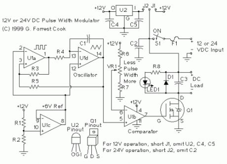
A pulse width modulator (PWM) is a device that may be used as an efficient light dimmer or DC motor speed controller. The circuit described here is a general purpose device that can control DC devices which draw up to a few amps of current. The circuit may be used in 12 Volt and 24 Volt systems with a few minor changes. This device has been used to control the brightness of an automotive tail lamp and as a motor speed control for small DC fans of the type used in computer power supplies. A PWM circuit works by making a square wave with a variable on-to-off ratio, the average on time may be varied from 0 to 100 percent. In this manner, a variable amount of power is transferred to the load. The main advantage of a PWM circuit over a resistive power controller is the efficiency, at a 50% level, the PWM will use about 50% of full power, almost all of which is transferred to the load, a resistive controller at 50% load power would consume about 71% of full power, 50% of the power goes to the load and the other 21% is wasted heating the dropping resistor. Load efficiency is almost always a critical factor in alternative energy systems. An additional advantage of pulse width modulation is that the pulses are at the full supply voltage and will produce more torque in a motor by being able to overcome the internal motor resistances more easily. Finally, in a PWM circuit, common small potentiometers may be used to control a wide variety of loads whereas large and expensive high power variable resistors are needed for resistive controllers. The main Disadvantages of PWM circuits are the added complexity and the possibility of generating radio frequency interference (RFI). RFI may be minimized by locating the controller near the load, using short leads, and in some cases, using additional filtering on the power supply leads. This circuit has some RFI bypassing and produced minimal interference with an AM radio that was located under a foot away. If additional filtering is needed, a car radio line choke may be placed in series with the DC power input, be sure not to exceed the current rating of the choke.
SPECIFICATIONSPWM Frequency: 400 HzCurrent Capacity: 3 Amps with IRF521 FET, more with IRFZ34N FETPWM circuit current: 1.5 ma @ 12V with no LED and no loadOperating Voltage: 12V or 24V depending on the configuration.
THEORYThe PWM circuit requires a steadily running oscillator to operate. U1a and U1d form a square/triangle waveform generator with a frequency of around 400 Hz. U1c is used to generate a 6 Volt reference current which is used as a virtual ground for the oscillator, this is necessary to allow the oscillator to run off of a single supply instead of a +/- voltage dual supply. U1b is wired in a comparator configuration and is the part of the circuit that generates the variable pulse width. U1 pin 6 receives a variable voltage from the R6, VR1, R7 voltage ladder. This is compared to the triangle waveform from U1-14. When the waveform is above the pin 6 voltage, U1 produces a high output. Conversely, when the waveform is below the pin 6 voltage, U1 produces a low output. By varying the pin 6 voltage, the on/off points are moved up and down the triangle wave, producing a variable pulse width. Resistors R6 and R7 are used to set the end points of the VR1 control, the values shown allow the control to have a full on and a full off setting within the travel of the potentiometer. These part values may be varied to change the behavior of the potentiometer. Finally, Q1 is the power switch, it receives the modulated pulse width voltage on the gate terminal and switches the load current on and off through the Source-Drain current path. When Q1 is on, it provides a ground path for the load, when Q1 is off, the load's ground is floating. Care should be taken to insure that the load terminals are not grounded or a short will occur. The load will have the supply voltage on the positive side at all times. LED1 is optional and gives a variable brightness response to the pulse width. Capacitor C3 smooths out the switching waveform and removes some RFI, Diode D1 is a flywheel diode that shorts out the reverse voltage kick from inductive motor loads. In the 24 Volt mode, regulator U2 converts the 24 Volt supply to 12 Volts for running the pwm circuit, Q1 switches the 24 Volt load to ground just like it does for the 12 Volt load. See the schematic for instructions on wiring the circuit for 12 Volts or 24 Volts. At the 1 amp current level, no heat sink is needed on Q1, if you will be switching more current, a heat sink is recommended. Q1 may be replaced with a higher current device such as an IRFZ34N, all of the current handling devices, switch S1, fuse F1, and the wiring between the FET, power supply, and load should be able to handle the maximum load current.
CONSTRUCTONThe prototype for this circuit was constructed on a regular IC proto board with parts and wires stuck into the proto board holes. One version of the finished circuit was used to make a variable speed DC fan, the fan was mounted on top of a small metal box and the PWM circuit was contained inside of the box (Fig 1). I built a simple circuit board (Fig 2) using a free circuit board CAD program, PCB (1) that runs on the Linux operating system. The circuit board image was printed on a PostScript laser printer onto a mask transfer product called Techniks Press-n-Peel blue film (2). The printed on film is then ironed on to a cleaned piece of single sided copper clad board. The board is etched with Ferric Chloride solution. Holes are drilled with a fine gauge drill bit, parts are soldered in, and the board is wired to the power and load. This technique is great for producing working boards in a short time but is not suitable for large numbers of boards. A board pattern is shown in Fig 3, this may be photo-copied onto a piece of press-n-peel blue film. Alternately, the dead-bug construction method may be used, this involves taking a piece of blank copper PC board, glueing a wire-wrap IC socket to the board with 5 minute epoxy, then soldering all of the parts to the wire wrap pins. Grounded pins can be soldered directly to the copper board.
USEThis circuit will work as a DC lamp dimmer, small motor controller, and even as a small heater controller. It would make a great speed control for a solar powered electric train. I have not tried the circuit with larger motors, in theory, it should work in applications such as a bicycle motor drive system, if you experiment with this, be sure to include an easily accessible emergency power disconnect switch in case the FET shorts on. Wire the circuit for 12 Volts or 24 Volts as per the schematic, connect the battery to the input terminals, and connect the load to the output terminals, be sure not to ground either output terminal or anything connected to the output terminals such as a motor case. Turn the potentiometer knob back and forth, the load should show variable speed or light.PartsU1:LM324N quad op-ampU2:78L12 12 volt regulatorQ1:IRF521 N channel MosFetD1:1N4004 silicon diodeLED1 Red LEDC1: 0.01uF ceramic disc capacitor, 25VC2-C5:0.1uF ceramic disk capacitor, 50VR1-R4:100K 1/4W resistorR5:47K 1/4W resistorR6-R7:3.9K 1/4W resistorR8:2.7K 1/4W resistorVR1:10K linear potentiometerF1:3 Amp, 28V DC fast blow fuseS1:toggle switch, 5 Amps
(View)
View full Circuit Diagram | Comments | Reading(1847)
Metal Detectors
Published:2013/7/28 20:02:00 Author:muriel | Keyword: Metal Detectors
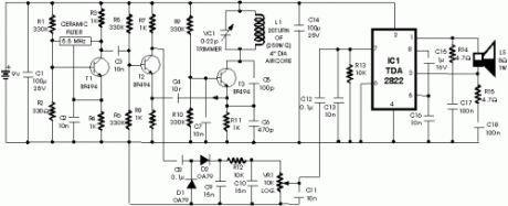
The circuit described here is that of a metal detector. The opera- tion of the circuit is based on superheterodyning principle which is commonly used in superhet receivers. The circuit utilises two RF oscillators. The frequencies of both oscillators are fixed at 5.5 MHz. The first RF oscillator comprises transistor T1 (BF 494) and a 5.5MHz ceramic filter commonly used in TV sound-IF section. The second oscillator is a Colpitt’s oscillator realised with the help of transistor T3 (BF494) and inductor L1 (whose construction details follow) shunted by trimmer capacitor VC1. These two oscillators’ frequencies (say Fx and Fy) are mixed in the mixer transistor T2 (another BF 494) and the difference or the beat frequency (Fx-Fy) output from collector of transistor T2 is connected to detector stage comprising diodes D1 and D2 (both OA 79). The output is a pulsating DC which is passed through a low-pass filter realised with the help of a 10k resistor R12 and two 15nF capacitors C6 and C10. It is then passed to AF amplifier IC1 (2822M) via volumecontrol VR1 and the output is fed to an 8-ohm/1W speaker. The inductor L1 can be constructed using 15 turns of 25SWG wire on a 10cm (4-inch) diameter air-core former and then cementing it with insulating varnish. For proper operation of the circuit it is critical that frequencies of both the oscillators are the same so as to obtain zero beat in the absence of any metal in the near vicinity of the circuit. The alignment of oscillator 2 (to match oscillator 1 frequency) can be done with the help of trimmer capacitor VC1. When the two frequencies are equal, the beat frequency is zero, i.e. beat frquency=Fx-Fy=0, and thus there is no sound from the loudspeaker. When search coil L1 passes over metal, the metal changes its inductance, thereby changing the second oscillator’s frequency. So now Fx-Fy is not zero and the loudspeaker sounds. Thus one is able to detect presence of metal.
(View)
View full Circuit Diagram | Comments | Reading(1352)
Economical Pump Controller
Published:2013/7/28 20:00:00 Author:muriel | Keyword: Economical Pump Controller
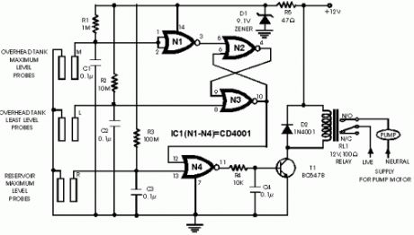
The automatic pump controller eliminates the need for any manual switching of pumps installed for the purpose of pumping water from a reservoir to an overhead tank (refer Fig. 1). It automatically switches on the pump when the water level in the tank falls below a certain low level (L), provided the water level in the reservoir is above a certain level (R). Subsequently, as the water level in the tank rises to an upper level (M), the pump switched off automatically. The pump is turned on again only when the water level again falls below level L in the tank, provided the level in the reservoir is above R. This automated action continues. The circuit is designed to ‘overlook’ the transient oscillations of the water level which would otherwise cause the logic to change its state rapidly and unnecessarily. The circuit uses a single CMOS chip (CD4001) for logic processing. No use of any moving electro-mechanical parts in the water-level sensor has been made. This ensures quick response, no wear and tear, and no mechanical failures. The circuit diagram is shown in Fig. 2. The device performed satisfactorily on a test run in conjunction with a 0.5 HP motor and pump. The sensors used in the circuit can be any two conducting probes, preferably resistant to electrolytic corrosion. For instance, in the simplest case, a properly sealed audio jack can be used to work as the sensor. The circuit can also be used as a constant fluid level maintainer. For this purpose the probes M and L are brought very close to each other to ensure that the fluid level is maintained within the M and L levels. The advantage of this system is that it can be used in tanks/reservoirs of any capacity whatsoever. However, the circuit cannot be used for purely non-conducting fluids. For non-conducting fluids, some modifications need to be made in the fluid-level sensors. The circuit can however be kept intact.
(View)
View full Circuit Diagram | Comments | Reading(1253)
Automatic Headlight Brightness Switch 1
Published:2013/7/25 21:04:00 Author:muriel | Keyword: Automatic , Headlight , Brightness , Switch
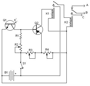
Driving the highway with your high-beam headlights can really increase your visibility, but can he a blinding hazard for other drivers. This simple circuit can be wired into your headlight switch to provide automatic switching between high and low beam headlights when there is oncoming traffic. It does this by sensing the lights of that traffic. In this way, you can drive safely with your high-beams on without blinding other drivers.
Parts:R1 5K 1/4W ResistorR2, R3, R4 5K PotQ1 NPN PhototransistorQ2 2N3906 PNP TransistorK1 Low Current 12V SPST RelayK2 High Current 12V SPDT RelayS1 SPST SwitchB1 Car BatteryMISC Case, wire, board, knobs for pots
Notes:1. Q1 should me mounted in such a way so it points toward the front of the car with a clear line of site. Suitable places are on the dashboard, in the front grill, etc.2. Adjust all the pots for proper response by testing on a deserted road.3. S1 enables and disables the circuit.4. B1 is, obviously, in the car already.5. Before you try to connect this circuit, get a wiring diagram for your car. Some auto manufacturers do weird things with wiring.6. Connection A goes to the high beam circuit, B goes to the headlight switch common and C connects to the low beam circuit. (View)
View full Circuit Diagram | Comments | Reading(880)
Headlights Timers
Published:2013/7/25 21:01:00 Author:muriel | Keyword: Headlights Timers
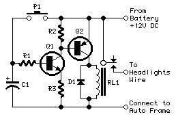
Parts:R1 4K7 1/4W ResistorR2,R3 1K 1/4W ResistorsC1 100µF 25V Electrolytic Capacitor (See Notes)D1 1N4002 100V 1A DiodeQ1 BC547 45V 100mA NPN TransistorQ2 BC327 45V 800mA PNP TransistorP1 SPST PushbuttonRL1 Relay with SPDT 10A min. switchCoil Voltage 12V. Coil resistance 150-600 Ohms
Comments:This device is a simple timer, allowing to keep on the headlights of your vehicle for about 1min. and 30sec., e.g. when accessing some dark place, without the necessity of coming back to switch-off the lights.
Circuit operation:Pushing on P1 allows C1 charging to full 12V battery supply. Therefore Q1 is driven hard-on, driving in turn Q2 and its Relay load. The headlights are thus activated by means of the Relay contact wired in parallel to the vehicle's headlights switch. RL1 remains activated until C1 is almost fully discharged, i.e. when its voltage falls below about 0.7V.The timing delay of the circuit depends by C1 and R1 values and was set to about 1min. and 30sec.In practice, due to electrolytic capacitors wide tolerance value, this delay will vary from about 1min. and 30sec. to 1min. and 50sec.An interesting variation is to use the inside lamp as a command source for the timer. In this way, when the door is opened C1 is charged, but it will start to discharge only when the door will be closed, substituting pushbutton operation.To enable the circuit acting in this way, simply connect the cathode of a 1N4002 diode to R1-C1 junction and the anode to the live lead of the inside lamp.This lead can be singled-out using a voltmeter, as it is the lead where a 12V voltage can be measured in respect to the vehicle frame when the lamp is on.
Notes:The Relay contact must be rated at 10A or more.Timings obtained trying different tolerance electrolytic capacitors for C1:100µF = 1'30 to 1'50 47µF = 0'45 to 1'05 220µF = 3'15 to 4'15 (View)
View full Circuit Diagram | Comments | Reading(1072)
Telephone line monitors
Published:2013/7/24 20:45:00 Author:muriel | Keyword: Telephone line monitors
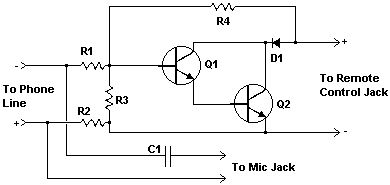
This nifty little circuit lets you record your phone conversations automatically. The device connects to the phone line, your tape recorder's microphone input, and the recorder's remote control jack. It senses the voltage in the phone line and begins recording when the line drops to 5 volts or less.
PartsR1 270K 1/4 W ResistorR2 1.5K 1/4 W ResistorR3 68K 1/4 W ResistorR4 33K 1/4 W ResistorC1 0.22uF 150 Volt CapacitorQ1, Q2 2N4954 NPN TransistorD1 1N645 DiodeMISC Wire, Plugs To Match Jacks On Recorder, Board, Phone Plug
Notes1. The circuit can be placed anywhere on the phone line, even inside a phone.2. Some countries or states require you to notify anyone you are talking to that the conversation is being recorded. Most recoders do this with a beep-beep. Also, you may have to get permission from the phone company before you connect anything to their lines.
(View)
View full Circuit Diagram | Comments | Reading(958)
| Pages:9/312 1234567891011121314151617181920Under 20 |
Circuit Categories
power supply circuit
Amplifier Circuit
Basic Circuit
LED and Light Circuit
Sensor Circuit
Signal Processing
Electrical Equipment Circuit
Control Circuit
Remote Control Circuit
A/D-D/A Converter Circuit
Audio Circuit
Measuring and Test Circuit
Communication Circuit
Computer-Related Circuit
555 Circuit
Automotive Circuit
Repairing Circuit