
Control Circuit
Index 7
Momentary Switch with 555 circuit
Published:2013/9/1 20:43:00 Author:lynne | Keyword: Momentary Switch with 555 circuit
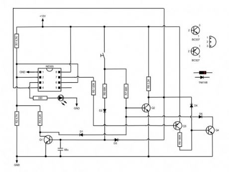
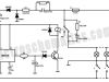
Based on NE555 this circuit turns on and off the IC output by a momentary switch. In other words it works as a mechanical latching relay, but the circuit backs to the start condition when you switch off the power supply. This feature is often required in automotive devices. No relay contacts are used, infact I connected the output to a led.
Once the momentary switch circuit is supplied the output (pin 3) keeps off because pin 2 and 6 are at half voltage. When the button is pressed Q1 turns on within a fraction of second because of the capacitor, while Q2 keeps off. By switching on Q1 leads pin 2 and 6 to low voltage, then the output gets high. When the button is pressed again Q2 switches on and leads pin 4 to low voltage (I used a pull up resistor), then the circuit takes the start condition. (View)
View full Circuit Diagram | Comments | Reading(1158)
Arduino Panic Alarm circuit
Published:2013/8/30 2:19:00 Author:lynne | Keyword: Arduino Panic Alarm circuit

Arduino is a family of microcontrollers (tiny computers) and a software creation environment (Arduino IDE) that makes it easy for you to create programs (called sketches) that can interact with the physical world. The Arduino environment has been designed to be easy to use for beginners who have no software or electronics experience. However, try to learn more/refresh your knowledge about arduino platfrom, before constructing this circuit. If you are new to Arduino, this link will help you get started http://arduino.cc. In addition, there is an active and supportive Arduino community that is accessible worldwide through the Arduino forums.The forums offer project development examples and solutions to problems that can provide inspiration and assistance as you pursue your own projects. Here is a simple Arduino guide for beginners www.me.umn.edu/courses/me2011/arduino/arduinoGuide.pdf
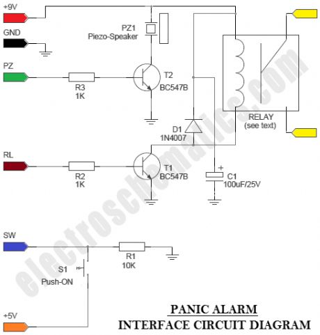
Panic Alarm circuit consists of two equally important parts. The first part is the ready-made Arduino Microcontroller board, and the second part is an interface circuit which can be wired on a piece of prototyping board. You can use any standard 9V battery to power the whole circuit, and the Push-ON (push ‘n’ hold) switch (S1) to activate the alarm function. An additional Electro-Magnetic Relay (EMR) is also attached to the interface circuit. With the help of this relay, it is easy to energize other (external) high-power blinkers or beepers, if necessary.
Panic Alarm Lab Notes
Prototype was constructed & tested using “Arduino UNO-R3” board
Sketch created,compiled & uploaded (to Arduino board) using Arduino IDE0022
Piezo-Speaker in the circuit is a “passive piezo-speaker”. Do not use an “active piezo-buzzer”
Use standard flexible wires for interconnection between two boards. Keep the wire length as short as possible
A 9VDC/1A SMPS power supply can be used as an alternative to the 9V battery. Remember to keep an eye on supply polarity
A “9VDC/225 Ohm” Electro-Magnetic Relay was used in the prototype. Contact Capacity of the relay (resistive Load) is 10A 250VAC/10A 30VD
(View)
View full Circuit Diagram | Comments | Reading(1292)
RF Based Wireless Remote Control System
Published:2013/8/30 2:13:00 Author:lynne | Keyword: RF Based Wireless Remote Control System
It is often required to switch electrical appliances from a distance without being a direct line of sight between the transmitter and receiver. As you may well know, an RF based wireless remote control system (RF Transmitter & RF Receiver) can be used to control an output load from a remote place. RF transmitter , as the name suggests, uses radio frequency to send the signals at a particular frequency and a baud rate.
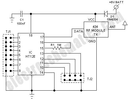
The RF receiver can receive these signals only if it is configured for the pre-defined signal/data pattern. An ideal solution for this application is provided by compact transmitter and receiver modules, which operate at a frequency of 434 MHz and are available ready-made. Here, the radio frequency (RF) transmission system employs Amplitude Shift Keying (ASK) with transmitter (and receiver) operating at 434 MHz. The use of the ready-made RF module simplifies the construction of a wireless remote control system and also makes it more reliable.
The current consumption with a supply voltage of near 5.4V is about 10 mA. Since the current consumption is very little,the power can also be provided by standard button cells. Recommended antenna length is 17 cm for 433.92 MHz, and a stiff wire can be used as the antenna. Remember to mount the antenna (aerial) as close as possible to pin 4 (ANT) of the transmitter module.
(View)
View full Circuit Diagram | Comments | Reading(1379)
PIC12F675 Microcontroller Based Security Alarm Circuit
Published:2013/8/29 1:19:00 Author:lynne | Keyword: PIC12F675 Microcontroller Based Security Alarm Circuit
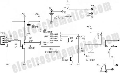
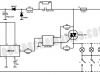
The output of the PIR sensor module (PIR1) is monitored through GP5 (pin 2) of PIC12F675. PIC12F675 is an 8-Pin Flash-Based 8-Bit CMOS Microcontroller. Note that,here the PIC12F675 microcontroller uses the internal clock oscillator at 4.0 MHz. When the motion is sensed, this output is high at about 3.3 V . You could still use this voltage as a valid logic high for IC1 by changing the code , but It is preferred to use this voltage to drive the base of a BC547 transistor (T1) so that at the collector we will have the full swing of the logic voltages.
When power supply is turned on by the on/off switch (S1), IC1 monitors the voltage at the collector of the transistor after a delay of about 60 seconds. This initial delay is introduced deliberately to avoid false triggerings, because the PIR sensor requires an initial stabilization time of about 10 to 60 seconds in order to function properly. A red LED (LED1) is connected to port GP0 of IC1 (pin7) with a current limiting resistor (R3) in series. The LED blinks at a slow rate during this delay time.
After this delay, IC1 starts monitoring the voltage at the collector of T1. The LED blinking pattern is now changed to indicate the “standby” mode. In standby mode, T1 is cut off, and the collector output is at logic high (+5 V). When a “valid” motion is sensed, the high output from the PIR sensor module saturates the transistor and the voltage at the collector drops down to logic low. Consequently, of port GP1 (pin 6) of IC1 goes high to switch on the 5V DPDT relay (RL1) through transistor T2. This output will remain High, as long as the motion exists, and this active condition is indicated by a steady-glow of LED1. DPDT Switching contacts of RL1 can be connected to powerful external lamps and/or alarms.
(View)
View full Circuit Diagram | Comments | Reading(2729)
One-Shot Timer for Energy Saving Lighting
Published:2013/8/29 1:14:00 Author:lynne | Keyword: One-Shot Timer for Energy Saving Lighting
Faced with the situation to control the time that the light is turned on, engineer Radu Preda from Romania has started experimenting with different circuits to save money spent on electricity. He has designed 2 energy saving lighting circuits, the first one uses a relay and the second one uses a optoisolator triac MOC3041 and a normal triac like BTA06-600 and both using the 555 one-shot timer.Note that the circuit is coupled directly to AC mains using the existing system in the building. A switch is used to start the timing and light one or more bulbs. The relay is powered from 12V and its contacts must outstand up to 1kW at 220V.
The LM555 IC is in a monostable configuration. The timing period is set with R4 and C3 and can be calculated with the formula:
T = 1.1 x C3 x R4
With the values from the schematic the working time of the lighting circuit is around 4 minutes. Power is applied through R1, C1, R2 and the voltage is stabilized at a value of 15V with the zener diode PL16Z.
(View)
View full Circuit Diagram | Comments | Reading(1159)
0.3 Second to 10 Hours Timer Relay with 4541 IC
Published:2013/8/28 1:27:00 Author:lynne | Keyword: 0.3 Second to 10 Hours Timer Relay with 4541 IC
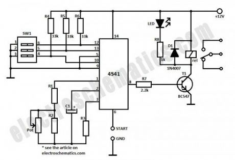
This timer relay circuit uses the CD4541 IC and has 2 timing variations configurable with RC elements. The specifications of this timer are:
modes of operation: astable/monostable
the output has a 6A/250V relay with NC/NO contacts
LED signals exiting the timing state
manual programming done with a DIP-switch
12V voltage operation
For the 0.3 second to 10 minutes timer version the potentiometer is 100kΩ, R1 = 9.1kΩ, R2 = 910kΩ, R3 = 220kkΩ and C1 = 100µF.
For the 15 seconds to 10 hours timer version the potentiometer is 1MΩ, R1 = 51kΩ, R2 = 1.2MΩ, R3 = 1.2MΩ and C1 = 1µF.
The operating mode is selected with the third contact of SW1:
ON position = monostable
O position = astable
In order to start the timining you have 2 possibilities: you either connect the START point to ground GND and in this case the timer starts when you connect it to the voltage supply or you can place a switch to start it.
All the resistors are 0.25W and C1 must have a good stability over time.
(View)
View full Circuit Diagram | Comments | Reading(7360)
Extended Period 555 On-Pulse Timer
Published:2013/8/20 23:01:00 Author:lynne | Keyword: Extended Period 555 On-Pulse Timer
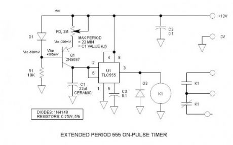
Long and longer timeout periods are frequent goals for the ubiquitous 555 timer. Generally, this is accomplished (albeit unreliably) by unusually large electrolytic timing capacitors. However, here the long period is accomplished by a more predictable ceramic or film capacitor and substantially reduced charging current. The reduced current is generated via a transistor regulated current source, and this current is also easily adjusted. I believe that this low current source trick is new to the world.
(View)
View full Circuit Diagram | Comments | Reading(1047)
Simple Touch Light Switch Circuit
Published:2013/8/19 0:53:00 Author:lynne | Keyword: Simple Touch Light Switch Circuit
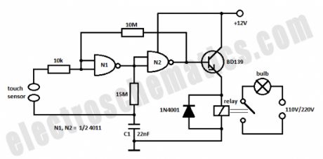
This is a very simple touch light switch circuit that uses the 4011 IC, one transistor and a relay. The C1 capacitor stores the switching state at a certain time and is charged or discharged according to the output signal of N1 gate.When the sensor is touched this state is returned to the input of N1 gate and so there is a change of switching state.
(View)
View full Circuit Diagram | Comments | Reading(1642)
Light-Operated Solid State Light Switch
Published:2013/8/15 21:16:00 Author:lynne | Keyword: Light-Operated Solid State Light Switch
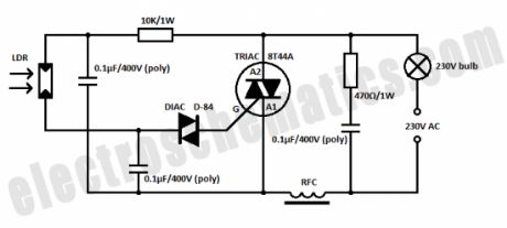
Here is a light-operated light switch circuit built with solid state components that is used to operate a lamp. During darkness the resistance of LDR is in the MΩ range and so the triac does not conduct. When the LDR is illuminated the resistance of the LDR will decrease and the triac will conduct and switched ON the lamp.The LDR must be placed so that is receiving light from the lamp too because this is the way that the lamps remains ON. Once the lamp is ON it can be switched OFF by interrupting the light falling on LDR. The RFC can be made by winding about 15 turns of 18 SWG wire over an insulated ferrite rod.
(View)
View full Circuit Diagram | Comments | Reading(1442)
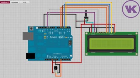
Digital Clock with Arduino and DS1307
Published:2013/8/15 21:12:00 Author:lynne | Keyword: Digital Clock with Arduino and DS1307

In this article you will learn how to make a digital clock using Arduino and the DS1307 RTC IC. What is DS1307 IC actually? Well, it is a Real Time Clock (RTC) IC that is simple to use, low cost and easy available. The IC basically is able to count the date and time accurately and it will continue its counting if the backup battery – coin cell battery is there although the mainsupply to the IC is cut off.
(View)
View full Circuit Diagram | Comments | Reading(1302)
Control a Relay with Arduino – Tutorial #5
Published:2013/8/14 21:03:00 Author:lynne | Keyword: Control a Relay with Arduino , Tutorial #5
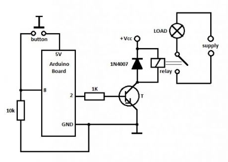
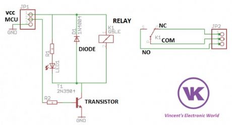
When the button is pressed the Arduino board will put pin 2 in HIGH state, meaning 5V on pin 2. This voltage is used to drive the transistor that will switch ON the relay and the load (in our case the fan) will be powered from the main power supply.
You cannot use the 5V from the USB to power up the transistor and the LOAD because the USB port usually delivers only 100mA, and this is not enough to switch the relay and the LOAD. That is why you must use an external power supply (Vcc) that is between 7 to 12 volts to power up the Arduino board and the transistor + relay. The load uses its own power supply, for instance if you use a light bulb then you might connect it to the 110/220V mains or any other power source.
(View)
View full Circuit Diagram | Comments | Reading(2008)
Temperature Controlled Relay with Arduino – Tutorial #6
Published:2013/8/13 21:31:00 Author:lynne | Keyword: Temperature Controlled Relay with Arduino , Tutorial #6

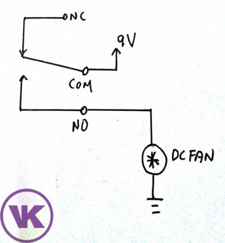
In this project, we are going to build something very simple project, a temperature controlled relay that is used to turn on a dc fan. You can actually change the DC Fan to other electrical devices such as light or servo motor. We are going to make an automatic fan that will be ON when the temperature rises above certain threshold temperature and OFF when it is below.
(View)
View full Circuit Diagram | Comments | Reading(1651)
Network Cable Tester
Published:2013/8/12 4:55:00 Author:lynne | Keyword: Network Cable Tester
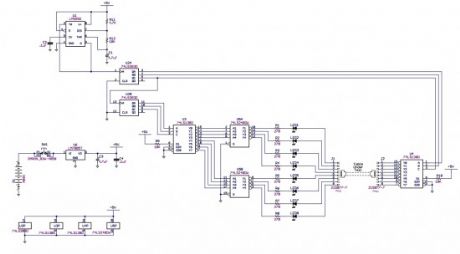
This network cable tester is designed for testing network cable with CAT 5 connectors, RJ-45. It can be modified to test any 8 conductor cable by replacing the RJ-45 jacks with the mating connectors of the cable to be tested.
(View)
View full Circuit Diagram | Comments | Reading(1578)
Soft Start for Flashlights
Published:2013/8/12 4:53:00 Author:lynne | Keyword: Soft Start for Flashlights

Application:
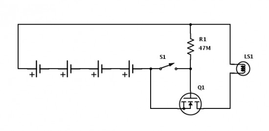
A project with only 2 parts, but is great for addressing an everyday situation that is irritating at best and dangerous at worst. This circuit protects the bulb in flashlights (FL) from high switch-on current to make the bulb last longer.Description:
For a standard incandescent flashlight (FL), this is a easy little modification make your FL bulbs last longer. High powered FLs typically run their bulbs hot to get a brighter light from them. They also have a much lower on-resistance when cold, so that when you turn them on, the bulb passes a much higher current than it was designed for. This is why the most common time for a bulb failure is when turning it on.
The transistor and resistor limit the current while turning on the circuit and protect the bulb from an initial high current turn on. A simple resistor in series with the bulb might be a tempting option, but there are a couple problems with that approach. Just adding a resistor would reduce the voltage available to the bulb, and aid longevity, but that would reduce the brightness. The resistor would also be wasting energy getting hot instead of using that energy for light. This solution is better in that it limits current at startup and wastes very little energy when in use and when off.
In this application, it might be easier to insert the batteries in the FL“backwards” so the circuit connections and parts have the best fit in the body of the FL. FL design was stagnant for decades, but now there are many new technologies available, and in some cases, it can even be easy to bring some of them to an older one you already have. In addition to this circuit, you could also take advantage of newer LED and battery technology to really increase the brightness, “on” time, and lamp life of your old FL.
 (View)
View full Circuit Diagram | Comments | Reading(1125)
Long Duration Timer
Published:2013/8/8 20:22:00 Author:lynne | Keyword: Long Duration Timer
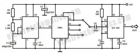
In order to create a long duration timer the 556 IC teamed up with a binary divider can provide delays as much as 16 times that set by the time constant of the first timer. You can use two 555 ICs instead of the 556.The first timer provides a delay of 7.5 minutes and the divided outputs give a delay of 15 min, 30 min, 1 hour and 2 hours respectively. The second timer is used to obtain the desired output pulse length. Additional dividers may be added to give longer delays.
(View)
View full Circuit Diagram | Comments | Reading(1135)
AC Power Line Hi/Lo Voltage Tester
Published:2013/8/7 20:59:00 Author:lynne | Keyword: AC Power Line Hi/Lo Voltage Tester

If you wish to test a line-powered device under both a 15% high and a 15% low voltage condition, you can use the circuit below. The circuit uses an 18v transformer with a 3 amp rating. A double pole, double throw toggle switch then switches in the transformer voltage in either a buck or a boost mode. In the buck mode, the transformer voltage is subtracted from the line voltage. In the boost mode, the transformer voltage is added to the line voltage. With an 18vac transformer the normal 120vac voltage is switched between 102vac and 138vac. For 240vac power line tests, use a 36vac transformer rated at 2A.
(View)
View full Circuit Diagram | Comments | Reading(1623)
AC Line Under/Over Voltage Alarm Circuit
Published:2013/8/7 20:57:00 Author:lynne | Keyword: AC Line Under/Over Voltage Alarm Circuit
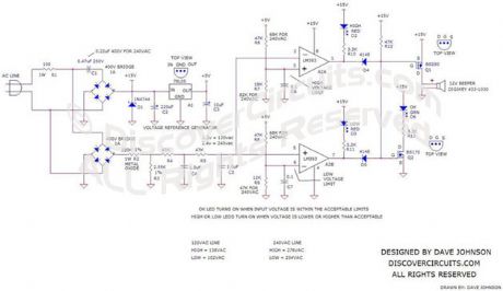

Power lines, which deviate much beyond normal voltages can damage expensive electronic equipment. The circuit below sounds an alarm whenever the line voltage is higher or lower than normal. I set the alarm limits at about +-15% from standard levels. The circuit rectifies and filters the power line signal. I set the resistor values, so the DC voltage produced is close to 1% of the RMS value of the line. Thus, a 120vac line would yield about 1.2v DC. That voltage is fed to a pair of voltage comparators.
The outputs of the comparators decide if the sampled voltage is above, below or acceptable. Three LEDs indicate the voltage range. A green LED is lit if the voltage is OK. If the voltage is outside normal levels, the circuit sounds an alarm using a small magnet or piezoelectric beeper. I have shown recommended resistor values for both 120vac and 240vac power lines.
(View)
View full Circuit Diagram | Comments | Reading(1720)
SOLID STATE RELAY REQUIRES ONLY 50uA DRIVE CURRENT CIRCUIT
Published:2013/8/7 20:53:00 Author:lynne | Keyword: SOLID STATE RELAY REQUIRES ONLY 50uA DRIVE CURRENT CIRCUIT
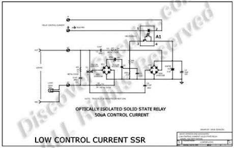
Most solid state relays require at least 5ma and often more input control current, to fully turn on the device. But such current levels often force battery powered circuits to use excessively large batteries. The relay hobby circuit shown below demands only 50uA of input current. This about 100 times lower than that needed by a typical optically isolated solid state relays. The circuit uses a combination of a high current triac and a very sensitive low current SCR, to control up to 600 watts of power to a load, while providing full isolation and transient protection.
[H-Corner/ads/i-HC-boombox.htm]
At the heart of the circuit is a Darlington type opto-isolator A1 from NEC. This device needs only 50uA of current through the LED section to activate the Darlington side. A bridge rectifier and a couple capacitors, strips off a bit of current from the 120vac line, through the load. A zener diode limits the generated DC voltage to 8v. When the opto-isolator is turned on, current is routed to the gate of a sensitive SCR. When turned on, the SCR routes current pulses to the main control triac, through a bridge rectifier. A 15v zener delays the trigger point of the triac slightly, so a minimum 30 volts peak to peak is always available to maintain current to the SCR circuit.
(View)
View full Circuit Diagram | Comments | Reading(1343)
RAIN ALARM
Published:2013/8/5 20:42:00 Author:lynne | Keyword: RAIN ALARM
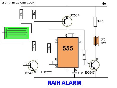
This circuit consumes no current until moisture is detected on the rain plate.
(View)
View full Circuit Diagram | Comments | Reading(0)
REACTION TIMER GAME
Published:2013/8/5 20:09:00 Author:lynne | Keyword: REACTION TIMER GAME
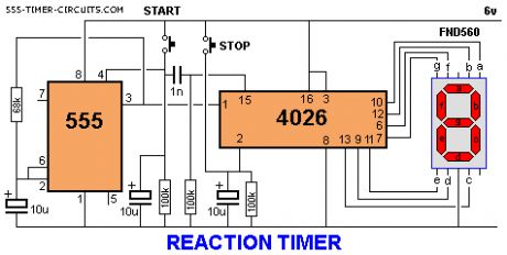
This is a game for two players. Player 1 presses the START button. This resets the 4026 counter chip and starts the 555 oscillator. The 555 produces 10 pulses per second and these are counted by the 4026 chip and displayed on the 7-Segment display. The second player is required to press the STOP button. This freezes the display by activating the Clock Inhibit line of the 4026 (pin 2).Two time-delay circuits are included. The first activates the 555 by charging a 10u electrolytic and at the same time delivering a (high) pulse to the 4026 chip to reset it. The second timer freezes the count on the display (by raising the voltage on pin 2) so it can be read.
(View)
View full Circuit Diagram | Comments | Reading(2673)
| Pages:7/312 1234567891011121314151617181920Under 20 |
Circuit Categories
power supply circuit
Amplifier Circuit
Basic Circuit
LED and Light Circuit
Sensor Circuit
Signal Processing
Electrical Equipment Circuit
Control Circuit
Remote Control Circuit
A/D-D/A Converter Circuit
Audio Circuit
Measuring and Test Circuit
Communication Circuit
Computer-Related Circuit
555 Circuit
Automotive Circuit
Repairing Circuit