
Index 36
Building an Adjustable Constant Current Load
Published:2012/11/29 0:22:00 Author:muriel | Keyword: Adjustable, Constant Current Load
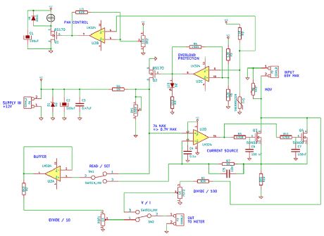
Constant current dummy load designs built around the venerable LM324 quad OPAMP have become quite popular in the hobbyist community ever since David Jones at the eevblog popularized the concept in one of his excellent videos. The basic concept has been around for a long time though, and it's essentially an OPAMP based current source design. The current source portion of thecircuit below is very similar to Dave's design. It always bothered me though that the original design didn't use the four OPAMPs in the LM324, and that there was limited protection in the circuit. Therefore, I decided to use one of the two spare OPAMPs for thermal overload protection and another to activate a cooling fan. This approach should result in a more reliable design which is an important consideration for test equipment.
Figure 1 shows the circuit schematic. The Current Source portion should be familiar to anyone that has seen similar designs on the web. The U2D OPAMP is a voltage follower that ensures the voltage at the 0.1 Ohm resistor follows the voltage applied to its non-inverting input. Therefore the current at the output through the 0.1 Oh resistor is I = Vi / (0.1) = 10 x Vi. I decided to use a 0.1 Ohm resistor (instead of the common 1 Ohm design)to allow larger currents. The smaller resistor value reduces the power dissipated in the resistor for a given output current. Furthermore, the source-to-ground voltage is also reduced thus ensuring that VGS is kept well above the MOSFET's threshold voltage for all practical operation conditions. I used two 50N06 N-channel MOSFETs in parallel to reduce the total Ron and improve reliability. In this design, the maximum current should be about 7A and it is limited by the 5W resistor I used; not by the MOSFETs. Larger currents can be achieved with a resistor capable of 10 or 20 W dissipation (which I didn't have handy). The input voltage should not exceed 60V (maximum VDS for these MOSFETs). As an added protection measure, I added a power MOV from the input to ground to protect the MOSFETs against high-voltage transients. (View)
View full Circuit Diagram | Comments | Reading(4230)
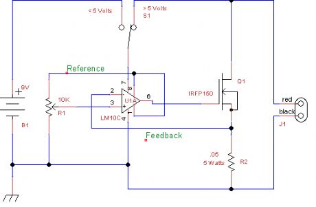
Constant Current Electronic Power Supply
Published:2012/11/29 0:21:00 Author:muriel | Keyword: Constant Current, Electronic Power Supply
View full Circuit Diagram | Comments | Reading(1240)
Solar Battery Charger
Published:2012/11/29 0:20:00 Author:muriel | Keyword: Solar Battery, Charger
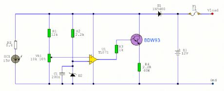
A solar battery charger that uses a shunt regulator to prevent overcharging. Circuit uses a 12V solar battery, but can be adapted for other voltages. (View)
View full Circuit Diagram | Comments | Reading(2184)
Under Voltage Circuit
Published:2012/11/29 0:19:00 Author:muriel | Keyword: Under Voltage Circuit
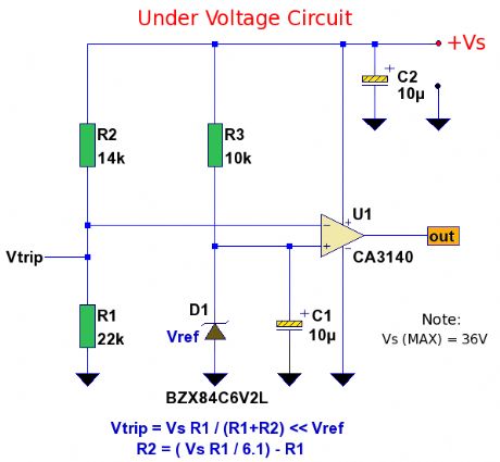
This under voltage circuit may be used as an add-on to an existing power supply or standalone. The circuit draws power from an existing power supply, which may be up to 36 Vdc. Once voltage drops below a preset level the output swings high. A CA3140 MOSFET op-amp is used as a comparator, the output can drive loads of up to 10mA so can drive a low current LED directly. Additional buffering is required for higher loads. (View)
View full Circuit Diagram | Comments | Reading(1057)
EMI Mains Filter
Published:2012/11/29 0:18:00 Author:muriel | Keyword: EMI , Mains Filter
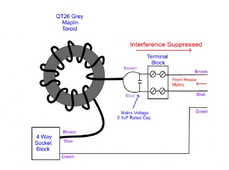
Modern society reliance on electrically driven appliances, creates Electro-Magnetic Interference (EMI) which manifests as electrosmog , a gathering phenomenon to which susceptible people are becoming unusually allergic as recently reported in the press.
This is prevalent from power lines, transmitters, electrical and electronic devices, plus data hash from computers in industry, shops, the home and is unavoidably all around us.
(View)
View full Circuit Diagram | Comments | Reading(2407)
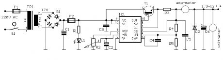
Radio Friendly Power Supply
Published:2012/11/26 1:08:00 Author:muriel | Keyword: Radio Friendly , Power Supply
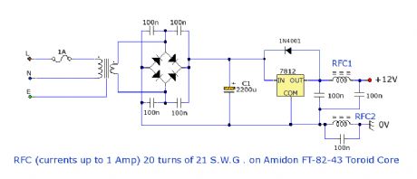
Power supplies should not create any unwanted interference across the radio spectrum. Switch mode power supplies are one of the strongest sources of interference, and harmonics can be heard throughout long, medium and short wave bands. This power supply, is extremely noise free, and therefore radio friendly. In addition, it has a very high rejection of line frequency and is suitable for powering receivers and small power transmitters. (View)
View full Circuit Diagram | Comments | Reading(1856)
1.5 to 37 Volt 30 Amp Power Supply
Published:2012/11/26 1:07:00 Author:muriel | Keyword: 1.5 to 37 Volt , 30 Amp, Power Supply
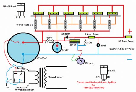
A modification to the 12V 30 Amp power supply. This version uses an LM317 to provide a variable 1.5 to 37 Volt regulated output with currents up to 30 Amps. Max has built his power supply into an old computer case and can be seen on YouTube under Project Icarus. (View)
View full Circuit Diagram | Comments | Reading(4177)
Power Zener Circuit
Published:2012/11/26 1:06:00 Author:muriel | Keyword: Power Zener Circuit
In this circuit a zener diode is amplified by a set of power transistors. The transistors substantially increase the current and power to the load. (View)
View full Circuit Diagram | Comments | Reading(1786)
Power Fail Alert
Published:2012/11/26 1:06:00 Author:muriel | Keyword: Power Fail Alert
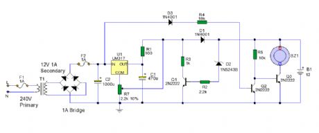
In this circuit an electricity supply (domestic or industrial) is continually monitored. Should the supply be interrupted then an alarm will sound for the duration of the interruption. It has battery backup and overcharge protection. (View)
View full Circuit Diagram | Comments | Reading(1115)
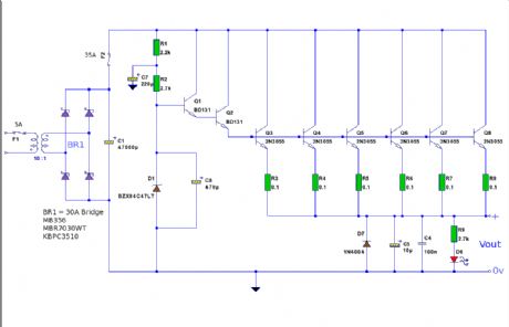
12 Volt 20 Amp Power Supply
Published:2012/11/26 1:05:00 Author:muriel | Keyword: 12 Volt , 20 Amp, Power Supply
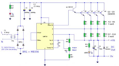
A 12 Volt high current 20 Amp power supply. The output voltage is variable from 12.2 Volt to 14.4V so can be set for any device requiring voltage and current in that range. This PSU uses an LM723 as the regulator, 4 parallel connected outboard pass transistors and has current limiting above 25 amps. (View)
View full Circuit Diagram | Comments | Reading(3817)
Multiple Output DC Converter
Published:2012/11/26 1:04:00 Author:muriel | Keyword: Multiple, Output, DC Converter
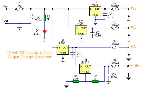
A DC converter circuit taking one single DC input and converting to parallel multiple DC outputs. (View)
View full Circuit Diagram | Comments | Reading(2338)
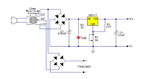
Adjustable Power Supply with Charger Output
Published:2012/11/26 1:04:00 Author:muriel | Keyword: Adjustable Power Supply , Charger Output
View full Circuit Diagram | Comments | Reading(2671)
Fast Electronic Fuse
Published:2012/11/26 1:03:00 Author:muriel | Keyword: Fast , Electronic Fuse
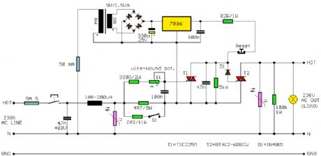
A fast electronic fuse designed to operate on 230V AC with an adjustable trip current. (View)
View full Circuit Diagram | Comments | Reading(1618)
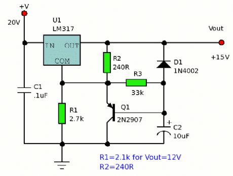
Variable Power Supply Using Fixed Regulator
Published:2012/11/26 1:03:00 Author:muriel | Keyword: Variable Power Supply, Fixed Regulator
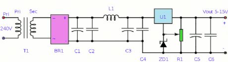
This is a similar power supply that I used to power my FM Transmitter. After suffering long problems with mains hum, this design using a pi filtered C-L-C approach. This circuit offers excellent ripple rejection. (View)
View full Circuit Diagram | Comments | Reading(933)
1.3V Power Supply
Published:2012/11/26 1:02:00 Author:muriel | Keyword: 1.3V , Power Supply

This is a replacement power source for 1.3V mercury cells or other small batteries. It has many uses and I use this circuit in my computer to power a front panel multi adapter which has a digital thermometer. (View)
View full Circuit Diagram | Comments | Reading(860)
Add-On Current Limiter for Power Supplies
Published:2012/11/26 0:59:00 Author:muriel | Keyword: Add-On, Current Limiter, Power Supplies
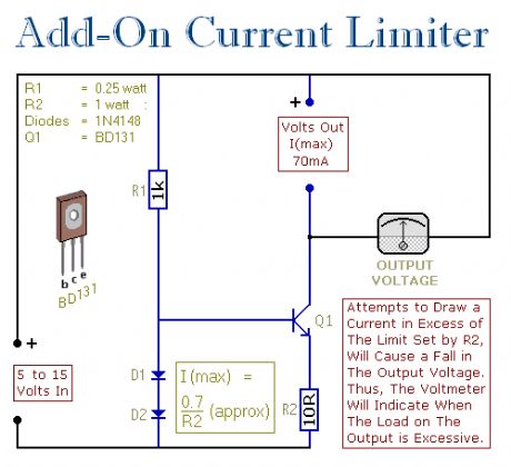
This circuit allows you to set a limit on the maximum output current available from your PSU. It's very useful when you power-up a project for the first time - or carry out a soak-test. By setting an upper limit on the current available from your PSU - you can protect both your power supply - and any device connected to it. It offers a simple and cheap alternative to the Current Limiting Power Supply. (View)
View full Circuit Diagram | Comments | Reading(1425)
Universal PSU
Published:2012/11/26 0:59:00 Author:muriel | Keyword: Universal PSU
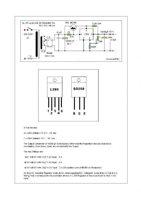
A Universal Power supply based on the L200 regulator, which includes an outboard pass transistor to boost output currents up to 4 amps. (View)
View full Circuit Diagram | Comments | Reading(1975)
Soft Start PSU
Published:2012/11/26 0:58:00 Author:muriel | Keyword: Soft Start, PSU
Two soft start power supplies. The output voltage slowly increases to the desired output. (View)
View full Circuit Diagram | Comments | Reading(1411)
Small Variable power Supply
Published:2012/11/26 0:58:00 Author:muriel | Keyword: Small Variable, power Supply
View full Circuit Diagram | Comments | Reading(1032)
Supply Voltage Indicator
Published:2012/11/26 0:57:00 Author:muriel | Keyword: Supply Voltage Indicator
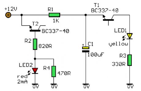
A novel supply voltage monitor which uses a LED to show the status of a power supply. (View)
View full Circuit Diagram | Comments | Reading(952)
| Pages:36/291 At 202122232425262728293031323334353637383940Under 20 |
Circuit Categories
power supply circuit
Amplifier Circuit
Basic Circuit
LED and Light Circuit
Sensor Circuit
Signal Processing
Electrical Equipment Circuit
Control Circuit
Remote Control Circuit
A/D-D/A Converter Circuit
Audio Circuit
Measuring and Test Circuit
Communication Circuit
Computer-Related Circuit
555 Circuit
Automotive Circuit
Repairing Circuit