
Index 24
Car charger for Nicd Battery Packs
Published:2013/3/21 4:15:00 Author:Ecco | Keyword: Car charger , Nicd Battery Packs
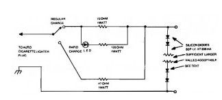
The Car charger for Nicd Battery Packs circuit is very suitable for portable charger, with a few components, allows you to build them in a small case.
The number of silicon diodes across the Car charger output is determined by the voltage of the battery pack.Figure each diode at 0.7 volt. For example, a 10.9- volt pack would require 10.9/0.7 = 15.57, or 16 diodes.
(View)
View full Circuit Diagram | Comments | Reading(978)
Nicd Charger Uses LEDs Constant Current
Published:2013/3/21 4:02:00 Author:Ecco | Keyword: Nicd Charger , LEDs , Constant Current
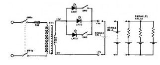
This Nicd charger circuit diagram is another simple NiCd battery charger, and I think its very interesting because uses LEDs to adjust the charging current.
As mentioned above, this Nicd charger circuit uses constant current LEDs to adjust charging current. It makes use of LEDs that pass a constant current of about 15 -mA for an applied voltage range of 2-18 V.They can be paralleled to give any multiple of 15 mA and they light up when current is flowing.
The circuit will charge a single cell at 15, 30 .or 45 mA or cells in series up to the rated supply voltage limit (about 14 V).
(View)
View full Circuit Diagram | Comments | Reading(1213)
5V to 15V Power Supply using 7805 IC Regulator
Published:2013/3/21 4:00:00 Author:Ecco | Keyword: 5V to 15V, Power Supply , IC Regulator
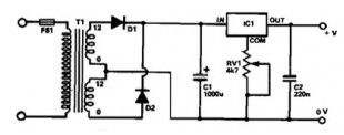
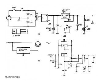
This power supply based 7805 IC regulator, it can provides a regulated output voltage of between 5 V to 15 VDC, it is adjusted and set by a preset resistor.
Maximum output current range of this power supply is 350 mA, its enough to supply powered calculator, radio, or cassete player. An integrated circuit regulates the output voltage and although this 7805 IC is generally applied to a fixed-voltage of 5 Vdc supply it is for a variable output voltage.
(View)
View full Circuit Diagram | Comments | Reading(1076)
Precision high voltage regulator
Published:2013/3/21 3:55:00 Author:Ecco | Keyword: high voltage regulator
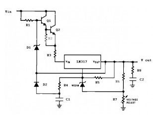
This is precision high voltage regulator circuit diagram based 3 terminal adjustable regulator LM317L IC.The circuit require input voltage Vin ≥ 178V and can provide output voltage ( V out) between 8 V to 160 V @ 25 mA current output.
(View)
View full Circuit Diagram | Comments | Reading(0)
Simple Split Rail Power Supply based LM380
Published:2013/3/21 3:50:00 Author:Ecco | Keyword: Simple Split Rail, Power Supply
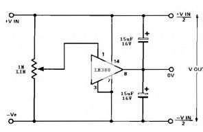


This split power supply circuit uses the of the popular LM380 audio power amplifier chip. The device is internally biased so that without having any input the output is held midway between the supply rails. R1, that will be initially set to mid-travel, is used to nullify any inbalance in the output.
Regulation of Vout depends upon the circuit feeding the LM380, but negative and positive outputs will track accurately irrespective of input regulation and unbalanced loads. The free air dissipation slightly more than 1 watt, and so will require extra cooling. The device is fully protected and will shut-down if its rated dissipation is exceeded. Current limiting occurs when the output current is higher than 1.3 A. The split power supply input voltage should never exceed 20 V.
(View)
View full Circuit Diagram | Comments | Reading(2047)
Fast Response Power Supply Protection
Published:2013/3/20 1:57:00 Author:Ecco | Keyword: Fast Response, Power Supply Protection
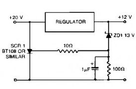
This Fast response power supply protection circuit is used to protect regulated power supply from the risks of undervoltage and overvoltage condition.
When working with a regulated power supply to reduce a supply voltage, there’s always the risk that component failure in the power supply may cause a severe overvoltage condition through the load. To deal with overvoltage conditions, the Fast response power supply protection circuit is designed to protect the load underovervoltage conditions. Component values given are for a 20 V supply with regulated output at 12V. The zener diode can be changed-according to any voltage is to be the maximum. When the voltage at the regulator output goes up to 13 V or higher, the zener diode breaks down-and triggers-the thyristor which will shorts out the supply line and blows the main fuse.
(View)
View full Circuit Diagram | Comments | Reading(1006)
Variable Power Supply with Adjustable Current Limit
Published:2013/3/20 1:54:00 Author:Ecco | Keyword: Variable Power Supply , Adjustable Current Limit
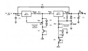
This circuit variable power supply with adjustable current limit using three terminal adjustable regulator LM117 which is used to regulate current and the voltage limits. Variable power supply input range is between 32 V to 40 VDC and can provide outputs up to 25 VDC and provide currents up to 1.2 A
Dioda D2 and D3 and Q2 are added to allow adjustment of output voltage to 0 volts. D1 protect both LM117 during an input short circuit
(View)
View full Circuit Diagram | Comments | Reading(2713)
Lead Acid Battery Charger with Current Limit
Published:2013/3/20 1:53:00 Author:Ecco | Keyword: Lead Acid, Battery Charger , Current Limit

The Lead Acid battery charger is based at charging voltage 2.4 V per cell, according to many manufacturers recommendations’. Pulse circuit the battery under charge with 14.4 V (6 CEUs x2.4 V per cell) at 120 Hz.
This Lead Acid battery charger design provides current limiting to protect the internal components battery charger circuit while limiting the charging rate to prevent severe damage to discharged lead-acid batteries. The recommended maximum charging time is typically about a quarter of the value of ampere-hour battery. For example, the maximum battery charging current to an average of 44 ampere-hour is 11 A. If the impedance of the load requires a larger charging current of 11 A current limit, the circuit will go into current limit. The amplitude of the charging pulse is controlled to maintain maximum peak charging current of 11 A (8 on average A).
(View)
View full Circuit Diagram | Comments | Reading(2601)
Adjustable Output Regulator with Op-Amp
Published:2013/3/20 1:52:00 Author:Ecco | Keyword: Adjustable , Output Regulator , Op-Amp
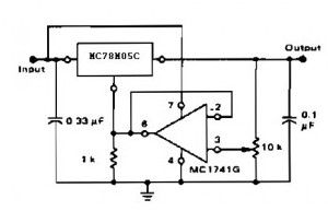
With adjustable voltage regulator the circuit voltage can be obtained varies from 7 to 20 VDC. This circuit requires a voltage input> = 20VDC
Circuit NotesThe addition of an op amp MC1741 allows adjustment to higher or intermediate values while retaining regulation characteristics. The minimum voltage obtainable with this arrangement is 2.0 volts higher than the regulator voltage.
(View)
View full Circuit Diagram | Comments | Reading(1236)
Universal Power Supply Module 3V-30V
Published:2013/3/20 1:51:00 Author:Ecco | Keyword: Universal , Power Supply Module , 3V-30V
This universal power supply circuit provides a variable voltage between 3-30 V. The power supply provides maximum current 1.5 A and with a few modifications and additions to modules can provide a higher current.
Adjustable regulator LM317 (U1) offers short-circuit protection and automatic current limiting at 1.5A. The input voltage to the regulator is supplied by DB1, a 4 A 100 PIV full-wave bridge rectifier. Capacitor C1 gives initial filtering. U1 provides extra electronic filtering included in the regulating function. The output level of the regulator is set by trim-pot R1. To prevent high-frequency oscillation Bypass capacitor added to the input and output of U1 . The current output of the transformer should be no less than 1.8 times the rated continuous-duty output of the supply. Which means that a 1.5-A supply should apply a 2.7-A transformer. For light or intermittent loads, a smaller 2.0-A transformer should be enough.
Wiring a 2nd Adjustable regulator LM317, U2, in parallel with U1 can be a quick and clean method to increase the current limiting threshold of the universal power supply to 3 A without having to sacrifice short-circuit protection. When more than 3 A is needed, the regulator module may be used to drive the base of one or more pass-transistors (see Fig. B).
(View)
View full Circuit Diagram | Comments | Reading(1338)
Current Source / Regulator
Published:2013/3/20 1:50:00 Author:Ecco | Keyword: Current Source, Regulator
The Current Source/Regulator circuit powers the load through the regulator’s input rather than its output. Since the regulator’s output sees constant dummy load R1, it attempts to consume a constant amount of current, regardless of what the voltage across the actual load really is. Therefore, the regulator’s input works as a constant current source for the actual load.
Thecurrent source circuit need power supply with any of the commonly available ± 15 or ± 12V . The voltage dropped over the regulator and dummy load lowered the total compliance voltage of the Current Source/ Regulator circuit. You set the load’s current with R1. The current equals 1.25 AAA x R.
(View)
View full Circuit Diagram | Comments | Reading(933)
Low Power 5V Switching Regulator
Published:2013/3/20 1:39:00 Author:Ecco | Keyword: Low Power, 5V , Switching Regulator
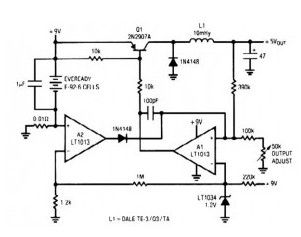
This simple switching regulator circuit have 5 V output, the input provide by a 9 V battery. Ithaving 80% efficiency and 50mA output capability.
How simple switching Regulator works:While Q1 is actually on, its collector voltage increases, delivering current through the inductor. The output voltage goes up, triggering A1′s(precision op amp LT1013) output to rise. Q1 cuts off as well as the output decays through the load.
The 100pF capacitor would ensure clean switching. The cycle repeats when the output falls low enough for A1 to turn on Transistor Q1. The 1µF capacitor ensures low battery impedance at high frequencies, preventing sag during switching.
(View)
View full Circuit Diagram | Comments | Reading(776)
Power Supply Splitter 9V to ± 5V
Published:2013/3/20 1:38:00 Author:Ecco | Keyword: Power Supply Splitter, 9V to ± 5V
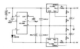
This power supply splitter circuit can divide the voltage of ± 5V only from a 9V battery. This circuit consists of three ICs. The first is IC ICL7660, these are monolithic, CMOS switched-capacitor voltage converters that invert, double, divide, or multiply a positive input voltage. Next is ICL7663 IC a positive voltage regulator. And the last ICL7664 for negative voltage regulator.
The oscillation frequency of the ICL7660 will be reduced with the external oscillator capacitor, so that it inverts the battery voltage more efficiently.
(View)
View full Circuit Diagram | Comments | Reading(1656)
Dual polarity 15V power supply
Published:2013/3/20 1:37:00 Author:Ecco | Keyword: Dual polarity, 15V power supply
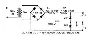
This simple split / dual polarity unregulated power supply circuit provides a +15 Volt and -15 Volt supply from a single transformer winding and one full-wave bridge.
A couple of zener diodes in series give you the voltage division and their centerpoint is grounded. (The filter capacitor should not be seated through its case). Since this power supply is unregulated type, so it will not recommended for high quality audio system.
(View)
View full Circuit Diagram | Comments | Reading(1295)
12V battery charger Max : 20 A rms
Published:2013/3/20 1:35:00 Author:Ecco | Keyword: 12V battery charger , 20 A rms
This 12V battery charger circuitcan charge12 voltbatteries withmaximumcurrent20 Arms.
(View)
View full Circuit Diagram | Comments | Reading(1084)
Electronic crowbar for AC and DC lines
Published:2013/3/20 1:34:00 Author:Ecco | Keyword: Electronic crowbar , AC and DC lines
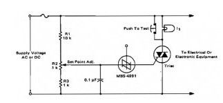
For positive protection of electrical or electronic equipment, use this against excessive supply voltage. Because of incorrect switching, electrical wiring, short circuits, or failure of regulators, an electronic crow-bar circuit can quickly place a short circuit through the power lines, thereby decreasing the voltage across the protected device to close to zero and blowing a fuse. The triac and SBS both are bilateral components, the circuit will be equally useful on alternating current or direct current supply lines.
Using the values shown for R1, R2, and R3, the crow-bar operating stage can be altered over the range of 60 to 120 volts dc or 42 to 84 volts ac. The resistor values may be changed to cover a different range of supply voltages. The voltage rating of the triac should be greater than the highest operating-point as set by R2. I1 is a low power incandescent bulb with a voltage rating similar to the supply voltage. It may be used to check the set point and operation of the unit by opening the test switch and adjusting the input or set point to fire the SBS.
(View)
View full Circuit Diagram | Comments | Reading(1204)
Constant Voltage Current Limited Charger
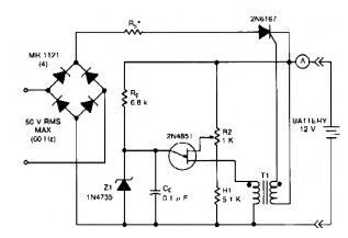
Published:2013/3/20 1:32:00 Author:Ecco | Keyword: Constant Voltage, Current Limited , Charger
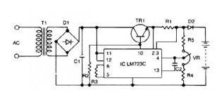
This 12v lead acid battery charger circuit based Regulator IC LM723C. The lead acid battery charger circuit can provide 12 V output voltage at 0.42 A maximum current. This battery charger circuit is design for 12 V Lead Acid battery.
(View)
View full Circuit Diagram | Comments | Reading(1438)
Thermally Controlled Nicad Charger
Published:2013/3/20 1:31:00 Author:Ecco | Keyword: Thermally Controlled , Nicad Charger
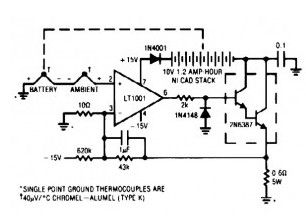
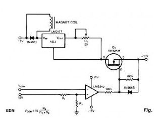
One method to charge Nikel Cadmium (NiCad) batteries quickly with out abuse is generally to measure battery cell temperature and taper the charge accordingly.
This nicad charger circuit works with a thermocouple for this function. Another thermocouple nulls out the effects of ambient temperature. The temperature difference between both thermocouples can determine the voltage, which will appears at the amplifier’s positive input. Since battery temperature rises, this small negative voltage (1 °C difference between the thermocouples equals 40 µV) gets larger.
The amplifier, working at a gain of 4300, gradually reduces the current over the nicad battery to keep its inputs at balance. The nicad battery charges at a high rate until heating occurs and the circuit then tapers the charge. The values given in the circuit limit the battery-surface temperature rise over ambient to about 5°C.
(View)
View full Circuit Diagram | Comments | Reading(821)
Nicad Battery Zapper
Published:2013/3/20 1:30:00 Author:Ecco | Keyword: Nicad Battery Zapper
This Nicad Battery zapper circuit clears internal shorts in nickel-cadmium batteries by burning them away. (View)
View full Circuit Diagram | Comments | Reading(1154)
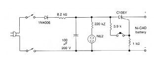
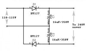
Traveller’s Shaver Adapter
Published:2013/3/20 1:29:00 Author:Ecco | Keyword: Traveller, Shaver Adapter
Thissimple circuitcanprotectyourelectricshaversfrom damagedue to wrongvoltage.
Many countries have 115 volts mains supplies. This can be a problem if your electric shaver is designed for 220/240 volts only. This simple rectifier voltage doubler enables motor driven 240 volt shavers to be operated at full speed from a 115 volt supply. As the output voltage is dc, the circuit can only be-used to drive small ac/dc motors. It cannot be used, for example, to operate vibrator-type shavers, or radios unless the latter are ac/dc operated.
(View)
View full Circuit Diagram | Comments | Reading(825)
| Pages:24/291 At 202122232425262728293031323334353637383940Under 20 |
Circuit Categories
power supply circuit
Amplifier Circuit
Basic Circuit
LED and Light Circuit
Sensor Circuit
Signal Processing
Electrical Equipment Circuit
Control Circuit
Remote Control Circuit
A/D-D/A Converter Circuit
Audio Circuit
Measuring and Test Circuit
Communication Circuit
Computer-Related Circuit
555 Circuit
Automotive Circuit
Repairing Circuit