
Battery Charger
Index 3
12 V Gelled-Electrolyte Battery Charger
Published:2012/9/19 21:39:00 Author:Ecco | Keyword: 12 V, Gelled-Electrolyte, Battery Charger

This circuit is a high-performance charger for gelled-electrolyte lead-acid batteries. This charger quickly recharges the battery and shuts off at full charge. It uses the well-known LM301A and LM350 ICs.Initially, charging current is limited to 2A. As the battery voltage rises, current to the battery decreases, and the current had decreased to 150 mA, the charge switches to a lower float voltage which prevents overcharge.When the start switch is pushed, the output of the charger goes to 14.5V. As the battery approaches full charge, the charging current decreases and the output voltage is reduced to 14.5V to about 12.5V, terminating the charging. Transistor then lights the LED as a visual indicator of full charge.
12V battery charger circuit schematic
?
One Response to “12 V Gelled-Electrolyte Battery Charger”
Source: electroschematic.com
(View)
View full Circuit Diagram | Comments | Reading(2679)
Wind powered battery charger
Published:2012/9/19 21:38:00 Author:Ecco | Keyword: Wind , powered, battery charger
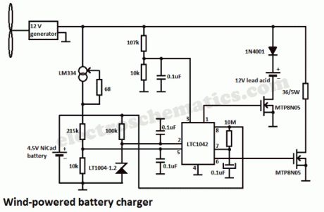
In this wind powered battery charger circuit the dc motor is used as a generator. The voltage output is proportional to its rpm. The LTC1042 monitors the voltage output and provides the following control function.1. if the voltage output is below 13.8V, the control circuit is active and the NiCad battery is charging through the LM334 current source. The lead-acid battery is not being charged.2. if the voltage output is between 13.8V and 15.1V, the 12V lead-acid battery is being charged at about 1-amp/hour rate (limited by the power FET).3. if generator voltage exceeds 15.1V (a condition caused by excessive wind speed or when the 12V battery is fully charged), the a fixed load is connected, which limits the generator rpm to prevent damage.This wind powered charger can be used as a remote source of power where wind energy is plentiful, such as on sailboats or at remote radio repeater sites. Unlike solar-powered panels, this system will function in bad weather and at night.
Battery Charger Schematic using wind energy
7 Responses to “Wind powered battery charger”
Source: electroschematic.com
(View)
View full Circuit Diagram | Comments | Reading(0)
NiMH Battery Charger circuit
Published:2012/9/19 21:37:00 Author:Ecco | Keyword: NiMH, Battery Charger
Here is a simple battery charger for the Nickel Metal Hydride battery that requires current regulated charging. The charger provides 140 mA current for quick charging of the battery.
Power supply section consists of a 0-18 volt AC 1 Ampere step-down transformer, a full wave bridge rectifier comprising D1 through D4 and the smoothing capacitor C1. Current regulation is achieved by the action of R1,R2 and the Epitaxial Darlington PNP transistor TIP 127. Resistor R1 keeps the charging current to 140 milli amperes. LED and resistor R2 plays an important role to control the base current of T1 and thus its output.
NiMH Battery Charger Circuit
Around 2.6 volts drop develops across the LED which appears at the base of T1. Emitter – base junction of T1 drops around 1.2 volts. So 2.6 – 1.2 volts gives 1.40 volts. So the current passing through R1 will be 1.40 V / 10 = 0.14 Amps or 140 Milli Amps. The LED act as the charging status indicator. LED lights only if the battery is connected to the output of circuit and the input voltage is normal.
2 Responses to “NiMH Battery Charger circuit”
Source: electroschematic.com
(View)
View full Circuit Diagram | Comments | Reading(2370)
Cell Phone charger using 1.5V battery
Published:2012/9/18 21:32:00 Author:Ecco | Keyword: Cell Phone charger, 1.5V battery
This article was received from Subham Chatterjee. Thank you!
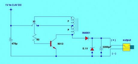
For the cell phone to charge, charger output must be above 4V and can deliver a maximum current of 500mA. This charger circuit will step up the voltage from 1.5V to 5V DC to reach the cell phone charging requirement. The circuit uses only an AA or AAA 1.5v battery (1V to 2.4V). The charger is composed of simple oscillator, a rectifier, and voltage regulator.The feedback winding F is composed 5 turns of #30 AWG magnetic wire and main winding P is composed of 6 turns of #24 AWG wire. The 5.1V zener diode and 2200uF capacitor regulates the output voltage to ensure proper charging.
The windings are not critical, you can experiment using different number of turns. If ever the charger doesn’t have any output, try to reverse the winding connection.
Cellphone charger circuit schematic
My opinion is that this can charge the cellphone battery only for short period of time because the 1.5 volt battery power capacity is much lower than the phone’s battery.
17 Responses to “Cell Phone charger using 1.5V battery”
(View)
View full Circuit Diagram | Comments | Reading(2386)
12V SCR Battery Charger
Published:2012/9/18 21:25:00 Author:Ecco | Keyword: 12V , SCR Battery Charger
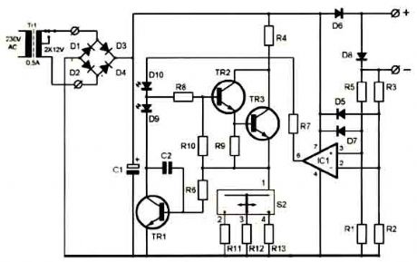
This battery charger circuit differs from the norm in a number of ways, all of which make it difficult to understand. For this reason, I do not recommend it for the beginner.Repairing /revamping a dead chargerWhat I started with was an inoperative 12amp battery charger. In hope of repairing it, I traced out the circuit, but did not like what I found—poor circuit design. So what I had to start with was an enclosure, ammeter, thermal overload interrupter, and center-tapped transformer all designed for battery charger application.
Since the maximum current delivered by the unit is a function of the transformer internal impedance, I recommend that the readers use the same type of transformer. If you are a good pack-rat (like me), you may already have a dead charger—or you can be on the lookout for one.
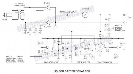
12V Battery Charger Schematic
SCR (Thyristor) RectifiersFirst of all, the two SCRs (silicon controlled rectifiers or thyristors) are connected with their anodes (stud or tab) grounded—this makes for excellent thermal transfer because no insulating hardware is required (if it is permissible to connect the negative terminal of the charger directly to the steel enclosure). If you do not wish to ground this point, use insulating hardware to electrically isolate the SCRs. This makes the transformer center-tap the positive terminal. The reason for this circuit placement is the ease of driving the SCR gates via the positive battery voltage—it is very unconventional as I have never seen this trick done before.
SCRs are the ideal power device choice for a battery charger because they can both regulate battery charging voltage and prevent fault current when the battery is inadvertently connected reverse. I have actually connected mine reverse and thought that the charger was inoperative until I realized what I had done.
Power Device SelectionI used two 2N690 stud-mount SCRs that I had available. Any in the series will work (2N683 through 2N690)—only the voltage rating differs and anything greater than 100V is good for the application. Other more inexpensive TO-220 candidates are: STMicroelectronics TYN616, Teccor/Littlefuse S6015L (isolated package), NXP 151-500C, or ON Seimconductor 2N6403G. Avoid sensitive gate devices.
Circuit CommonNormally circuits use a negative common—that is just the way the world seems to work, but in this case, it was more convenient to make the positive rail the common point and all visualization must be made with this in mind. The only exception is D7 that was installed to prevent damage should the battery get connected reverse. For visualization, simply short out D7. The conventional ground symbol is used for the negative rail. This tends to tie your brain in knots…
Voltage ReferenceA good battery charger tapers off when the battery voltage is above about 14V. For this to function, D6 is a 5.1V shunt zener regulator that puts out -5.1V relative to the positive rail. It is biased via R8.
Ramp GeneratorC1 and R4 form a ramp generator that generates a negative going sawtooth voltage (relative to the positive rail). It is reset to the positive rail via Q1 and Q2 at line voltage zero crossing. At zero crossing, there is no voltage at the anodes of D3 & D4 (relative to the positive rail), Q1 is off, Q2 is on and C1 is shorted. At all other points in the AC line cycle, C1 is charging. My line frequency is 60HZ. For 50HZ, increase the value of R4 to 82K.
Error AmplifierU1A
Source: electroschematics.com (View)
View full Circuit Diagram | Comments | Reading(3252)
12V Battery checker circuit
Published:2012/9/18 21:23:00 Author:Ecco | Keyword: 12V, Battery checker
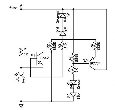
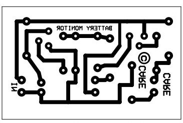
This is a 12V battery checker circuit that uses 3 LEDs that light up at their respective voltages. The red LED lights up when the battery voltage is between 8 to 10V, the orange one at voltages between 10.5V to 12V and the green one when the battery voltage is above 12.5V.This is a tried and tested battery checker circuit using one NPN and one PNP transistor. A PCB is given along with the schematic.
6 Responses to “12V Battery checker circuit”
(View)
View full Circuit Diagram | Comments | Reading(2760)
Car Battery Charger with transistors
Published:2012/9/18 21:21:00 Author:Ecco | Keyword: Car Battery Charger , transistor
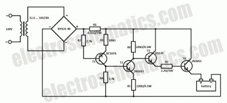
This car battery charger circuit can be used to charge 12V and 6V batteries. If it is used a transformer that can deliver 4A to 5A at a voltage between 12.6V and 16V then we can get rid of the switch for 6V or 12V batteries.
12V car battery charger circuit schematic
The car battery charging current is automatically limited to 4.2A. If there is a 600mV voltage on R1 (4A thru it), then the T1 transistor starts to conduct. Excessive charging current is avoided because the current value on T3′s base is limited. The difference between applied load current (at T4′s collector) and real voltage of the battery is balanced thru T4′s collector-emitter junction.
The power input of T4 (2N3055) is the product of load current and voltage difference already mentioned. When charging 6V car battery this power reaches a maximum of 40W. The rectifier diodes must be able to deliver 4A at 40V. T4 2N3055 must be mounted on a good heatsink in order to dissipate the heat.?
2 Responses to “Car Battery Charger with transistors”
Source: electroschematics.com
(View)
View full Circuit Diagram | Comments | Reading(3175)
Pulse-Charging Battery circuits
Published:2012/9/16 21:54:00 Author:Ecco | Keyword: Pulse-Charging Battery
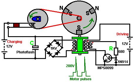
With this system, the rotor is started spinning by hand. As a magnet passes the triple-wound tri-filar coil, it induces a voltage in all three coil windings. The magnet on the rotor is effectively contributing energy to the circuit as it passes the coil. One winding feeds a current to the base of the transistor via the resistor R. This switches the transistor hard on, driving a strong current pulse from the battery through the second coil winding, creating a North pole at the top of the coil, boosting the rotor on its way. As only a changing magnetic field generate a voltage in a coil winding, the steady transistor current through coil two is unable to sustain the transistor base current through coil one and the transistor switches off again. (View)
View full Circuit Diagram | Comments | Reading(3475)
Free energy Battery Charger
Published:2012/9/16 21:46:00 Author:Ecco | Keyword: Free energy , Battery Charger

With this system, the rotor is started spinning by hand. As a magnet passes the triple-wound tri-filar coil, it induces a voltage in all three coil windings. The magnet on the rotor is effectively contributing energy to the circuit as it passes the coil. One winding feeds a current to the base of the transistor via the resistor R. This switches the transistor hard on, driving a strong current pulse from the battery through the second coil winding, creating a North pole at the top of the coil, boosting the rotor on its way. As only a changing magnetic field generate a voltage in a coil winding, the steady transistor current through coil two is unable to sustain the transistor base current through coil one and the transistor switches off again. (View)
View full Circuit Diagram | Comments | Reading(13283)
12V Analogue Battery Volt Meter
Published:2012/9/16 20:50:00 Author:Ecco | Keyword: 12V , Analogue Battery , Volt Meter
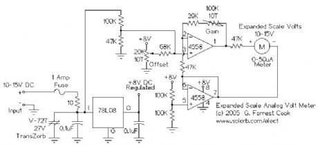
This circuit is used to measure the voltage on a 12V (nominal) lead acid rechargeable battery system. It was specifically designed for use in solar powered systems, but is general enough that it can be used for automotive or other 12V systems. Lead acid batteries normally spend their working lifetime in the voltage range of 11-15 Volts. This meter circuit was designed to show the voltage range of 10-15V on an analog meter movement, it can be used to show the battery charge state from empty to full. (View)
View full Circuit Diagram | Comments | Reading(1880)
Ni-Cd Baterry Charger 12-18V
Published:2012/9/12 20:44:00 Author:Ecco | Keyword: Ni-Cd , Baterry Charger, 12-18V
A clever charger circuit that safely can charge any Ni-Cd battery. Offers charge current sellection, polarization detection and protection and the ability to connect many batterys in siries. Ni-Cd bateries can be recharged more than 1000 times before become useless. the charging current shoud be the 1/10 of the (Ah) of the battery. The bateries need 14 hours to be fully charged. (View)
View full Circuit Diagram | Comments | Reading(3924)
Battery Charge Current Indicator
Published:2012/9/6 20:01:00 Author:Ecco | Keyword: Battery Charge , Current Indicator
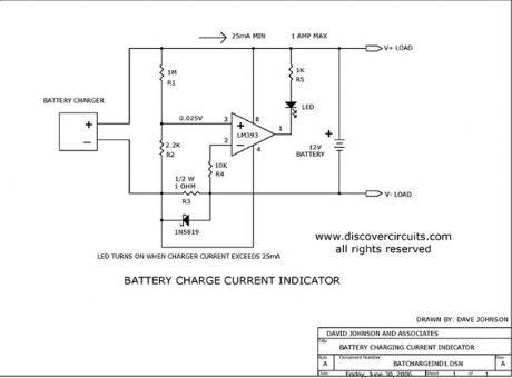
This circuit turns on a LED whenever it detects at least 25ma of battery charge current.
Source: discovercircuits (View)
View full Circuit Diagram | Comments | Reading(0)
+5v Powered Charge Pump Battery Charger
Published:2012/9/4 20:44:00 Author:Ecco | Keyword: +5v, Powered Charge Pump , Battery Charger
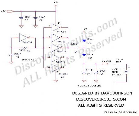
The circuit below will trickle charge a four cell pack of AA or AAA NiMH batteries. The circuit draws current from the +5v available a USB connection and pumps about 70ma of current into the battery. This should be enough current to fully charge a pack of 2500ma-hour cells in about 36 hours. The circuit uses a single 74HC14 hex Schmitt trigger inverter in conjunction with a voltage doubler charge pump circuit.
Source: discovercircuits (View)
View full Circuit Diagram | Comments | Reading(1415)
Auto-Off 12V NiCd Battery Charger
Published:2012/9/4 1:40:00 Author:Ecco | Keyword: Auto-Off , 12V , NiCd Battery Charger
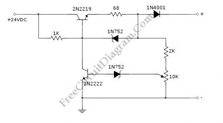
NiCd/NiCad battery charger circuit is still needed since some application demanding high current is still rely on NiCd type, since this type is still superior in term of high current output (low internal resistance) and low cost. This battery charger circuit is used to charge 12V NiCd battery at around 74 mA until battery is fully charged. This circuit need around 4 hours to fully recharge a totally empty/dead battery, depends on the battery capacity. Here is the schematic diagram of the circuit:
This circuit is basically a current source with auto cut-off. The current regulation is done by maintaining a fix voltage across a 68R at the emitter of 2N2219 transistor. This voltage is stabilized by a 5.6V zener diode 1N752, which keep the voltage at 68R resistor at around 5V, giving a constant current of 74 mA. The auto-off feature work by monitoring the output voltage (before the 1N4001 diode) relative to ground, as this voltage increases in accordance with the battery voltage which is being charged. After the battery voltage reach the fully-charged level, the lower 1N752 zener diode will pass the current to activate the 2N222 transistor, which short the upper transistor’s base, turning off the charging process. To calibrate the shut off point, connect a 270 ohm / 2 Watt resistor across the charge terminal and adjust the pot until the charging terminal voltage show 15.5V level.
(View)
View full Circuit Diagram | Comments | Reading(2994)
Passive Aircraft Receiver
Published:2012/8/29 2:08:00 Author:jailer | Keyword: Aircraft Receiver
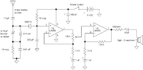
The Passive Aircraft Receiver is basically an amplified crystal radio designed to receive nearby AM aircraft transmissions. The passive design uses no oscillators or other RF circuitry capable of interfering with aircraft communications so it should be fine inside the cabin of the aircraft. Nevertheless, check the regulations before using this receiver on a commercial airliner. New security regulations probably prohibit this device on commercial flights. Do not expect to hear two-way aircraft transmissions with this receiver! It is a short-range receiver only.
The detector diode is a 1N5711, HP2835 or similar Schottky detector diode. The 10 megohm resistors provide a small diode bias current for better detector efficiency. The tuning capacitor may be any small variable with a range from about 5 pF to about 15 or 20 pF. The 0.15 uH inductor may be a molded choke or a few turns wound with a small diameter. Experiment with the coil to get the desired tuning range. The aircraft frequencies are directly above the FM band so a proper inductor will tune FM stations with the capacitor set near maximum capacity. (The FM stations will sound distorted since they are being slope detected.) Other capacitor and inductor combinations may be selected to tune other bands if desired. (Try the CB band at 27 MHz.) The LM358 dual op-amp draws under 1 ma so the battery life is quite long. A speaker amplifier may be added to drive a speaker or low-z earphone. The antenna can be a couple of inches if the receiver is near the transmitter or a couple of feet for maximum range. The selectivity is reduce as the antenna length is increased so best performance is achieved with the shortest acceptable antenna. Try increasing the 1.8 pF capacitor value when using very short antennas and decreasing it for long antennas. The receiver could be built into a small plastic box with a short antenna inside. (View)
View full Circuit Diagram | Comments | Reading(2207)
3.6W mobile phone battery charger circuit diagram
Published:2012/8/12 20:47:00 Author:Ecco | Keyword: 3.6W , mobile phone , battery charger
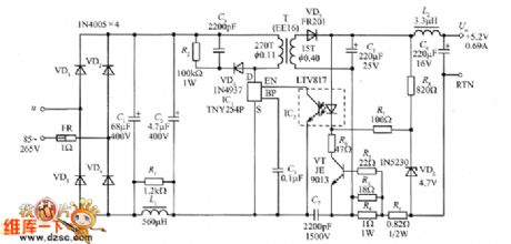
The3.6W charger circuit special for mobile phone is shown as the figure, andthe power supplyhas constant current / constant voltage output characteristics, and the no-load power consumption is less than 100mW. It can provide constant current charging for nickel-metal hydride (NiMH) batteries or nickel cadmium (NiCd) batteries, lithium ion ( Li = ion) batteries inmobile phone. Its main technical index: AC input voltage u = 85 ~~ 265V, output voltage Uo = 5.2V , the maximum output current Iom = 0.697A, output power Po, = 3.6W.
(View)
View full Circuit Diagram | Comments | Reading(4977)
Storage battery automatic charger 3
Published:2011/11/10 2:44:00 Author:May | Keyword: Storage battery, automatic charger

Familiar storage battery automatic charger can achieve the purpose of automatic control by detecting storage battery voltage when it ischarging. But when it has charging current, justified voltage of storage battery will be too high, so it is hard to decide the degree of charging by storage battery voltage. This text introduces an automatic storage battery charger.
The circuit is shown in diagram 4-10. It is theautomatic charger and its core is thethyristor components. When charger is connectedto discharged storage battery, thyristor VS is breaking over at every positive half period, and it will charge to the battery. In the end of positive half period, when charge voltage is lower than storage battery voltage, thyristor VS is cut off. When positive half period sarts, VS is in the cut-off stateat this time, the comparing of charge voltage and reference starts in order to decide whether VS is breaking over or not. When justified voltage of battery reaches to the certain value (about 13.5V), VT will not have current and VS will be cut off. (View)
View full Circuit Diagram | Comments | Reading(1520)
Voltage limiting nickel-cadmium battery charger circuit
Published:2011/11/10 2:37:00 Author:May | Keyword: Voltage limiting , nickel-cadmium battery charger
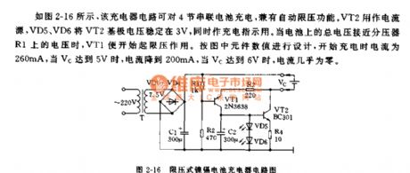
As shown in diagram 2-16, this charger circuit can charge to four series battery. This circuit also has theautomatic voltage limiting function. VT2 is used for current source. VD5, VD6 and VT2 can stabilize VT2's base voltage at 3V. Meanwhile they are used as charge lights. When the total voltage on the battery closes to the voltage on voltage divider R1, VT1 will start thevoltage limiting function. It is designed according to numeral value of element in the diagram, the currentis 260mAwhen it starts to charge, when Vc reaches to 5V, the current drops to 200mA, when Vc reaches to 6V, the current is almost zero. (View)
View full Circuit Diagram | Comments | Reading(1509)
Charging circuit using UBA2008 charging switch chip
Published:2011/11/30 20:28:00 Author:May | Keyword: Charging circuit , charging switch chip
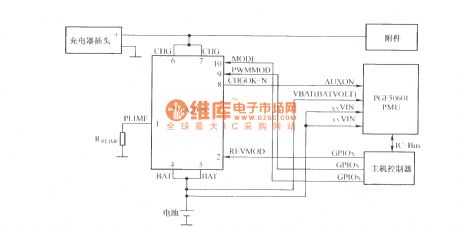
UBA2008 is the charging intelligent management chip with pulse way produced by Philips. The device integrates a low- resistance power switch which can be used for charge controlling of single cell Li-Ion or three NiMH cells or in the pre- charging or fast charging modes. It has current limiting , overvoltage protection, thermal protection and electrostatic discharge (ESD) protection, and it integrates the security mechanisms in battery charging process to ensure its safe operation.
(View)
View full Circuit Diagram | Comments | Reading(1113)
Multi-functional automatic charger circuit
Published:2011/10/26 21:17:00 Author:May | Keyword: Multi-functional automatic charger
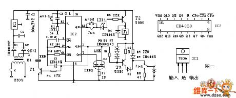
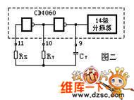
The working principle is shown in Figure one. It is the controller with CD4060 being the core. CD4060 is the 14-bit binary serial counting/frequency divider and oscillator. It has two parts: one is the 14 levels of frequency divider, and its frequency division coefficient is 16-16384 (it is output by Q4,¯Q14). Another part is the oscillator, which may be the RC oscillator composed of the external connecting resistor and capacitor. f=1/2.2RT CT. It is shown in Figure two. This installment is the oscillator composed of the C4, R2, R3, and the frequency approximately is the 0.2Hz. LED2 is the bi-color light emitter diode.
(View)
View full Circuit Diagram | Comments | Reading(2471)
| Pages:3/13 12345678910111213 |
Circuit Categories
power supply circuit
Amplifier Circuit
Basic Circuit
LED and Light Circuit
Sensor Circuit
Signal Processing
Electrical Equipment Circuit
Control Circuit
Remote Control Circuit
A/D-D/A Converter Circuit
Audio Circuit
Measuring and Test Circuit
Communication Circuit
Computer-Related Circuit
555 Circuit
Automotive Circuit
Repairing Circuit