
Battery Charger
Index 4
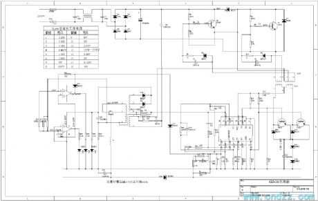
Intelligent pulse electric bike charger diagram
Published:2011/11/29 1:21:00 Author:Ecco | Keyword: Intelligent , pulse , electric bike charger
View full Circuit Diagram | Comments | Reading(8480)
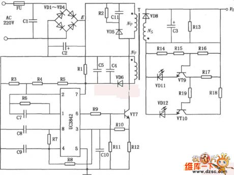
Electric bicycle battery charger circuit diagram
Published:2011/12/8 1:39:00 Author:Ecco | Keyword: Electric bicycle , battery charger
View full Circuit Diagram | Comments | Reading(4649)
Charging circuit composed of μA741
Published:2011/10/20 22:38:00 Author:Rebekka | Keyword: Charging circuit
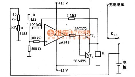
The figure shows the charging circuit composed of μA741. The battery voltage passes RP1 and adds to the inverting input terminal of A1. When the battery voltage is low, A1 outputs high, VT1 and VT2 turn on, the relay K will be energized, then the contacts K1-1 close. The charging power supply charges for the battery. When the battery is fully charged, the voltage is increased, A1 outputs low level, VT1 and VT2 stop, the relay K loses power,then the K1-1 disconnects, the battery will stops charging. (View)
View full Circuit Diagram | Comments | Reading(1692)
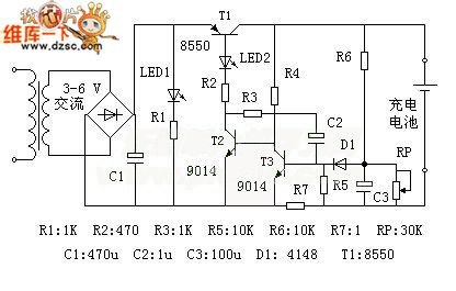
Lithium battery charger circuit diagram
Published:2011/10/17 1:29:00 Author:Ecco | Keyword: Lithium battery charger
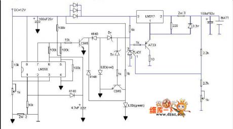
In this circuit, when it is in charging status, red light flashing shows that it is charging, and the green light flashing shows it is going to be full, then green light is lit completely, then it is full. As long as you have a 12V power supply, after finishing the circuit, you do not install the battery firstly, and adjusting the adjustable resistor in right corner make the battery output be 4.2V, then transferred adjustable resistor in the left corner make the pin 3 of LM358 be 0.16V, then the charging current is 380mA, and the circuit is ultra-fast, and three diodes connected in parallel is used to prevent overheating of LM317, and LM317 must add heat sink. The transistor shown in the figure can choose any model.
(View)
View full Circuit Diagram | Comments | Reading(3373)
The circuit of mobile phone charger
Published:2011/9/26 1:12:00 Author:Rebekka | Keyword: Mobile phone charger
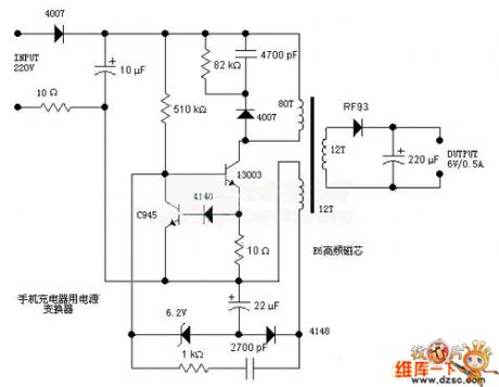
Here is the schematic diagram of the mobile phone charger circuit:
(View)
View full Circuit Diagram | Comments | Reading(7550)
Storage and Ni-MH Batteries Automatic Charger Circuit Diagram
Published:2011/9/14 22:43:00 Author:Rebekka | Keyword: Storage , Ni-MH Batteries , Automatic Charger
Batteries, Ni-MH battery automatic battery charger circuit, nickel hydrogen batteries, rechargeable battery are widely used in daily life, but often because of improper charge, the battery dies prematurely.
Properties: 1. The charger has a pulse current limiting charge, trickle charge and other functions in order to achieve intelligent charge without human care.2. The charger is triggered by battery power. There is no voltage output without connecting the battery; only the battery is connected correctly, the charge current will output. It has short circuit protection or reverse protection.3. The circuit has awide application. It performs in: ⑴ Wide input voltage range; ⑵ As long as you adjust the potentiometer, it will be suitable for other types of rechargeable batteries. (View)
View full Circuit Diagram | Comments | Reading(5115)
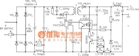
+6.7 V, 0.56A Constant current cell phone battery charger circuit composed of TNY254P
Published:2011/9/25 22:07:00 Author:Ecco | Keyword: +6.7 V, 0.56A , Constant current , cell phone , battery charger
View full Circuit Diagram | Comments | Reading(2380)
Motorcycle charging circuit diagram
Published:2011/9/14 22:16:00 Author:Rebekka | Keyword: Motorcycle charging
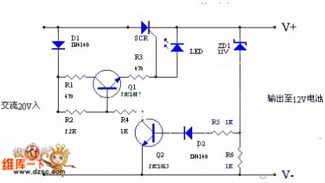
The circuit uses ACpositive half cycle charge. Charging speed is fast and it can extend battery life. People use the charger on ordinary motorcycle. It has an excellent performance and saves 5% fuel. It is a practical charging circuit. Working principle: (shown as the figure)AC voltage is also added to the D1 and SCR. It passes the half-wave rectifier D1 to R1、R2、Q1、R3 and provides trigger voltage to SCR. SCR is charging to the battery at this time. When the battery voltage isup to 13.5V, the ZD1 will be conducted. The voltage passing R5、D2 provides bias to Q2, thenQ2 will be conducted. Q1 reverse bias will be closed. SCR stops outputting when battery voltage is lower than 13-13.5V.
(View)
View full Circuit Diagram | Comments | Reading(6290)
Battery charging circuit composed of MIC5158
Published:2011/9/14 5:56:00 Author:Sophia | Keyword: Battery charging circuit
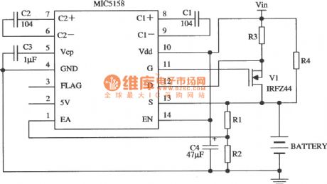
Constant-current charging circuit composed of the MIC5158 is as shown. In the whole process of charging, the circuit provides a constant current (35 mV/R3), until the battery voltage is charged to Vfl:. Vfl is float charge voltage (V). When float voltage is satisfied, MOSFET tube was turned off, and the R4 provides access forthe charge current. (View)
View full Circuit Diagram | Comments | Reading(1498)
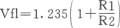
BQ2058T charging and discharging protection device circuit
Published:2011/9/12 22:04:00 Author:John | Keyword: protection device
BQ2058 and BQ2058T / X are specifically for the series combination of lithium-ion battery. In the circuit, BQ2058T can achieve the connection of two lithium-ion batteries in series and BQ2058X can achieve the connection of three or four series Li-ion batteries. Extremely low operating current makes lithium-ion battery generator not over-discharge during storage. And the systematic effective discharge loads can not be increased. In the internal parts of the lithium-ion battery generator, BQ2058T / X is the part of the low-loss charge and discharge control and protection system. The BQ2058T discharging protection device is shown.
(View)
View full Circuit Diagram | Comments | Reading(1614)
DS2760 lithium-ion battery protection circuit
Published:2011/9/12 22:04:00 Author:John | Keyword: lithium-ion battery
DS2760 has a 25mΩ sense resistor inside, which can detect two-way (charging and discharging) current (but its resistance and loss are bothe extremely small). The current resolution is 0.625mA and the dynamic range is within l.8A. It isalso with current cumulative function. The voltage measurement resolution is 48mV. Its temperature measurement resolution is up to 0.125 ℃. The digital converted by the A / D converter is stored in the corresponding memory container. It is connected with the main system through a single interface, thus leading it to be able to do management and control on lithium-ion battery power supply. Therefore, it is able to read / write access and control with internal memory container.
(View)
View full Circuit Diagram | Comments | Reading(2576)
Circuit Diagram of Solar-energy Nickel-cadmium Cell Charger
Published:2011/9/12 23:47:00 Author:Zoey | Keyword: Solar-energy, Nickel-cadmium Cell, charger
The picture above shows circuit diagram of nickel-cadmium cell that uses solar energy.The solar panel can provide 6V voltage, LT1073 will detect charge current through the 13Ω resistor and willmaintain 16mA fixed charging current in the nickel-cadmiumcell.LT1073 will shut off the charging circuit when the output voltageon thesolar panelofthelow-voltage detector descends to 4V.When the voltageascends toabove 5V, the cell can be recharged again. (View)
View full Circuit Diagram | Comments | Reading(1366)
Battery Quick Charger Circuit of Digital Potentiometer XC9104
Published:2011/8/25 22:45:00 Author:Michel | Keyword: Digital Potentiometer, Battery Quick Charger Circuit
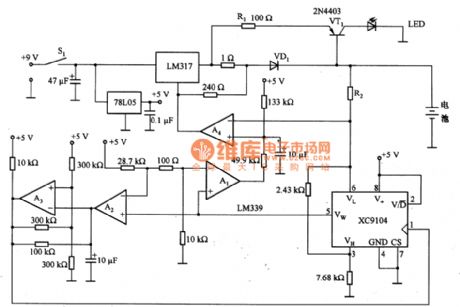
The above picture is battery quick charger circuit of digital potentiometer XC9104.When the power switch S1 switches on, 9 V voltage begins to charge the battery via LM317.When S1 switches on,Vw end voltage of XC9104 rises automatically,thus sliding port Vw is linked to VL end.In this state, A1 outputs high level, LM317 charges batteries quickly.The battery charges and the voltage gradually rises and XC9104 Vw end voltage rises automatically.A3 harmonic oscillator amplitude increases periodically according to the proportion that XC9104 remains. (View)
View full Circuit Diagram | Comments | Reading(2613)
Circuit diagram of small-size battery charger available to choosing charging time
Published:2011/9/9 8:01:00 Author:Vicky | Keyword: small-size battery charger , choosing charging time
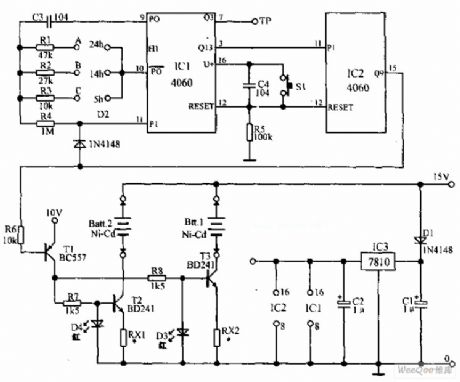
Small-size battery charging circuit which can choose charging time is shown in the above picture. The charger has the required constant current source digital circuit timer for charging safely. It can be used to charge 12 pieces of nickel-cadmium batteries. There are three grades of charging time for choice, and they are 5 hours, 14 hours, and 24 hours. The voltage adaptor of 15V outputs voltage supply the power for the circuit. 15V DC voltage is sent to the two constant current sources to charge the battery. In addition, IC3 (7810) provides the stable 10V power voltage for the timer。 (View)
View full Circuit Diagram | Comments | Reading(1754)
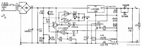
Lithium battery quick charger composed of LM3420-8.4
Published:2011/9/8 7:02:00 Author:Felicity | Keyword: Lithium battery, quick charger
This circuit adopted the specialized lithium battery charger LM3420-8.4 and it’s simple and have high performance and can charges two lithium batteries quickly. When the charging voltage reaches the rated value (with a single lithium battery it’s 4.2V), the charging current drops down to avoid permanent damage of lithium battery caused by overvoltage.
(View)
View full Circuit Diagram | Comments | Reading(2228)
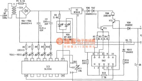
Lead accumulator charger circuit diagram
Published:2011/9/7 6:54:00 Author:Vicky | Keyword: Lead accumulator charger circuit
Lead accumulator charger circuit is shown in the above picture. The charger adopts constant voltage type charging. It controls the end of charging by the reduction of the charging current brought by the gradually adequate battery power. There is no need to worry about over-charging or lack of charging. When the power is on, the level of U1A inverting end , pin2, is always lower than the non-inverting input end, pin3. Therefore, pin 1 of U1A outputs high level, which makes Q1 saturate and conducted. It is as effective as the grounding of pin ADJ of U2, and the output of U2 is 1.2V with the charging end of 0.6A. It presents light load under such circumstance, and DS2 green luminous diodes is lighted. When the button S2 is pressed down, pin3 of U1A is grounded, pin2 is connected with the positive pole of the power via R1, then the U1A outputs low level, DS2 red luminous diode is lighted, and DS1 goes out. (View)
View full Circuit Diagram | Comments | Reading(2418)
Lead-acid cell over-charging protector circuit diagram
Published:2011/9/7 6:56:00 Author:Vicky | Keyword: lead-acid cell , over-charging protector circuit
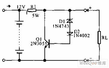
Lead-acid cell over-charging protector circuit is shown in the above picture. The protector can prevent middle size or large size lead-acid cell with capacity between 2 and 30 Ah from over-charging in the process of floating charging (the cell provides power for the load while being charged by trickle charge or solar panel). When it is not in the process of charging, Q1 cannot conduct the electricity due to the impedance of D1. When the charging voltage rises to about 14V, transistor Q1 (2N3055) is conducted, and splits the battery current to prevent the electrolyte from evaporating, which is beneficial for heat dissipation. Q1 should be assembled in a medium size heating panel. NTE143A can be also play the role of Q1. (View)
View full Circuit Diagram | Comments | Reading(2827)
Vehicle nickel-cadmium battery charger circuit diagram
Published:2011/9/7 6:58:00 Author:Vicky | Keyword: vehicle nickel-cadmium battery charger circuit
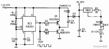
Vehicle nickel-cadmium battery charger circuit is shown in the above picture. It makes use of NE555 timer and two voltage multiplier circuits composed of power transistor so as to convert the voltage of vehicle battery from 12V to above 20V and then charge the 12V nickel-cadmium battery without changing the current. The voltage which has been multiplied sends the power current to three-end current stabilizer. NE555 are connected and form multi-vibrator, and the switch frequency is 1.4KHz. The charging current is set at 50mA, which can charge 10 pieces of 500mA·h nickel-cadmium batteries. (View)
View full Circuit Diagram | Comments | Reading(2390)
Circuit diagram of charger with diminishing pulse charging current exponentially
Published:2011/9/7 7:04:00 Author:Vicky | Keyword: charger, diminishing pulse charging current exponentially
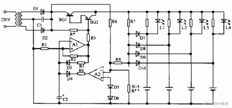
Circuit diagram of charger with diminishing pulse charging current in accordance with index is shown in the above picture. A1 and A2 constitute controlled multi-vibrator. Set the threshold value at around 1.45V. Back electromotive force generated by the polarized electric fields of the battery during charging would directly influence the output state of A2. During the test, when conducting pulse charging to the current, the increasing and decreasing speed of the polarized electric field strength and the depth of electrochemical reaction inside the battery present exponentially changing. The circuit utilizes this discipline to regulate the frequency and pulse brand of the pulse charging current and to realize the goal of controlling.
(View)
View full Circuit Diagram | Comments | Reading(2305)
Circuit diagram of prolonging the lifetime of nickel-cadmium battery
Published:2011/9/7 7:00:00 Author:Vicky | Keyword: nickel-cadmium battery, prolonging the lifetime
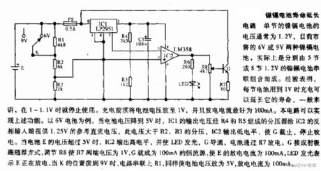
Circuit diagram of prolonging the lifetime of nickel-cadmium
Generally, the voltage of a single nickel-cadmium battery is 1.2V. 6V or 9v nickel-cadmium battery sold in the market now is in fact made of 5 or 8 nickel-cadmium battery of 1.2V in serial. Experience suggests that the lifetime of a battery can be prolonged when it was charged with still 1V left. Generally speaking, a battery should not be used when there is 1~1.1V left. The battery voltage must be reduced to 1V before charging, and the best discharging current is 100mA. The circuit in the picture can realize the above function. Take 6V battery as an example. When the battery voltage reduces to 5V, output voltage of IC1 provides the reference DC voltage of 1.25V for inverting input end of IC2 by voltage divider composed by R4 and R5. The reference voltage is higher than the divided voltage of R2 and R3. IC2 outputs low level which stops G, and the discharging stops. When the voltage of battery E is higher than 5V, IC3 outputs high level, and makes LED lighted, G conducted, and battery discharges via R7. (View)
View full Circuit Diagram | Comments | Reading(1313)
| Pages:4/13 12345678910111213 |
Circuit Categories
power supply circuit
Amplifier Circuit
Basic Circuit
LED and Light Circuit
Sensor Circuit
Signal Processing
Electrical Equipment Circuit
Control Circuit
Remote Control Circuit
A/D-D/A Converter Circuit
Audio Circuit
Measuring and Test Circuit
Communication Circuit
Computer-Related Circuit
555 Circuit
Automotive Circuit
Repairing Circuit