
power supply circuit
Index 132
Electronic_crowbar_circuit_using_an_SBS_and_a_triac
Published:2009/7/21 6:03:00 Author:Jessie
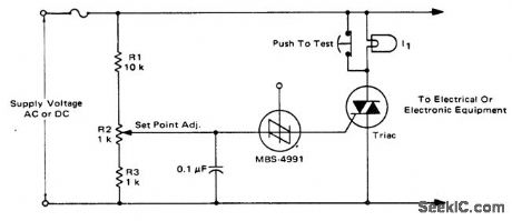
Electronic crowbar circuit using an SBS and a triac. This circuit protects equipment by placing a short-circuit across the line, thereby blowing the fuse. It works on DC circuits as well as AC types since the SBS and triac are both bilateral devices (courtesy Motorola Semiconductor Products Inc.). (View)
View full Circuit Diagram | Comments | Reading(2178)
SOR_full_range_power_controller_incorporating_an_SUS
Published:2009/7/21 6:02:00 Author:Jessie
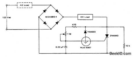
SOR full-range power controller incorporating an SUS (courtesy Motorola Semiconductor Products Inc.). (View)
View full Circuit Diagram | Comments | Reading(656)
Feedback_control_circuit_to_trigger_a_thyrister
Published:2009/7/21 6:01:00 Author:Jessie
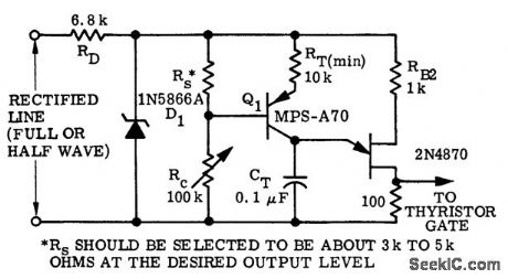
Feedback control circuit to trigger a thyrister (courtesy Motorola Semiconductor Products Inc.). (View)
View full Circuit Diagram | Comments | Reading(699)
Regulated_DC_motor_control_with_feedback_from_optical_sensor
Published:2009/7/21 5:59:00 Author:Jessie

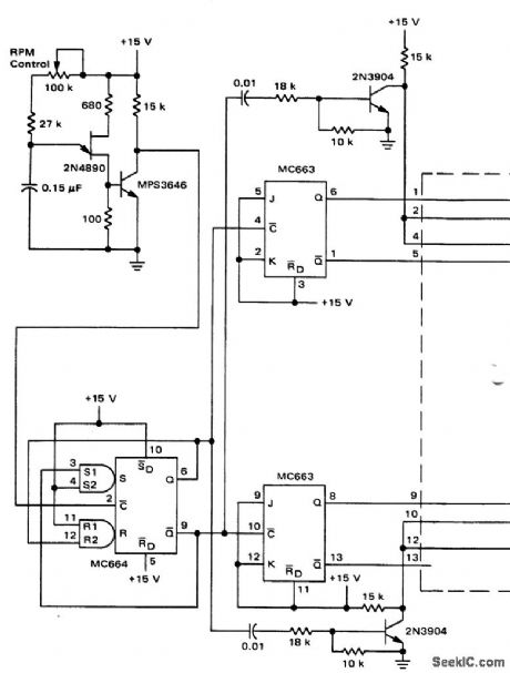
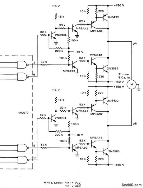
Regulated DC motor control with feedback from optical sensor (courtesy Motorola Semiconductor Products Inc.).
(View)
View full Circuit Diagram | Comments | Reading(972)
7_KV_AND_450_V_OSCILLATOR_TYPE_CRT_SUPPLY
Published:2009/7/21 5:58:00 Author:Jessie
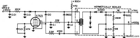
Pentode audio oscillator feeds hermetically sealed transformer-rectifter-filter unit.-NBS, Handbook Preferred Circuits Navy Aeronautical Electronic Equipment, Vol. 1, Electron tube Circuits, 1963, p N14-4. (View)
View full Circuit Diagram | Comments | Reading(583)
Variable_speed_control_for_induction_motors_1
Published:2009/7/21 5:57:00 Author:Jessie


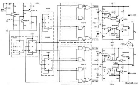

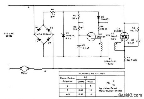
Variable speed control for induction motors (courtesy Motorola Semiconductor Products Inc.). (View)
View full Circuit Diagram | Comments | Reading(886)
5000_V_D_C_FROM_26_V_D_C
Published:2009/7/21 5:56:00 Author:Jessie
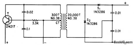
Uses transistor as sinusoidal oscillator. Voltage-doubling capacitors keep ripple below 0.01%.-R. D. Morrow, Inexpensive Converter Gives 5,000 Volts D-C, Electronics, 35:28, p 54. (View)
View full Circuit Diagram | Comments | Reading(600)
Triac_motor_speed_control_with_feedback
Published:2009/7/21 7:35:00 Author:Jessie
Triac motor speed control with feedback (courtesy Motorola Semiconductor Products Inc.). (View)
View full Circuit Diagram | Comments | Reading(2113)
Constant_current_motor_drive
Published:2009/7/21 7:34:00 Author:Jessie
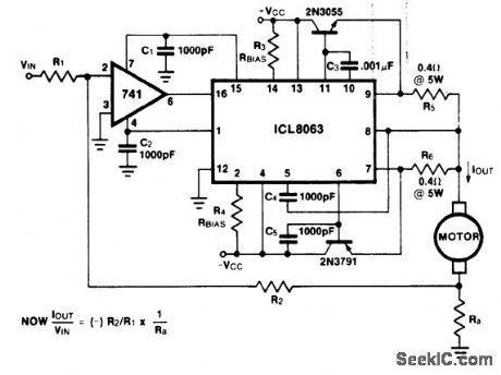
Constant-current motor drive. All capacitors should be at least 50 working volts and resistors the half-watt type, except those valued at 0.4 ohm and Ra. Use heat sinks for the power transistors with thermal compound. This circuit can be used where there is some likelihood of stalling or lockup, If the motor locks the current drive remains constant and the system does not destroy itself (courtesy Intersil, Inc.). (View)
View full Circuit Diagram | Comments | Reading(822)
Triac_heater_temperature_control_circuit
Published:2009/7/21 6:16:00 Author:Jessie
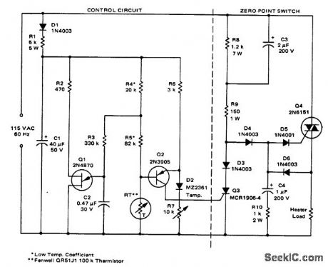
Triac heater temperature control circuit (courtesy Motorola Semiconductor Products Inc.). (View)
View full Circuit Diagram | Comments | Reading(2194)
Low_cost_light_dimmer_using_an_SBS_and_triac
Published:2009/7/21 6:14:00 Author:Jessie

Low-cost light dimmer using an SBS and triac. Shunting the SBS with two 20K resistors minimizes the flash-on effect (courtesy Motorola Semiconductor Products Inc.). (View)
View full Circuit Diagram | Comments | Reading(959)
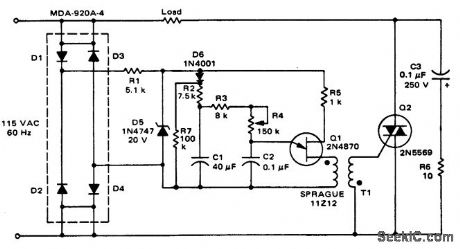
Triac_overvoltage_protection_circuit_with_automatic_reset
Published:2009/7/21 6:13:00 Author:Jessie
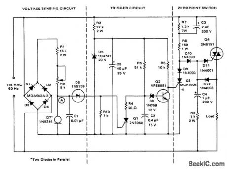
Triac overvoltage protection circuit with automatic reset. If the voltage at point A exceeds 11 volts during any half-cycle D6 fires and turns on SOB Q1, removing power from the load (courtesy Motorola Semiconductor Products Inc.). (View)
View full Circuit Diagram | Comments | Reading(1463)
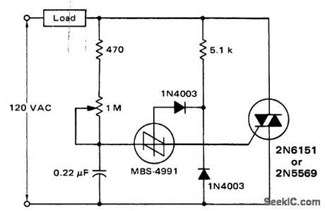
Hysteresis_free_power_controller_using_an_SBS_and_a_triac
Published:2009/7/21 6:10:00 Author:Jessie
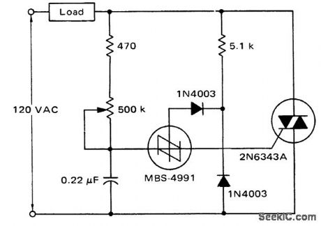
Hysteresis-free power controller using an SBS and a triac (courtesy Motorola Semiconductor Products Inc.). (View)
View full Circuit Diagram | Comments | Reading(796)
THERMOMETER_ADAPTER
Published:2009/7/8 2:04:00 Author:May
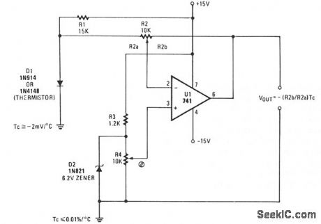
A simple op amp and silicon diode are the heart of the temperature-to-voltage converter that will permit you to use an ordinary voltmeter-either analog or digital-to measure temperature. User adjustments make it possible for a reading of either 10 mV or 100 mV to represent 1°F or C.
Temperature sensor D1 is a 1N4148 silicon diode. It has a temperature coefficient of -2 mV/°C. U1, a 741 op amp, is connected as a differential amplifier. A voltage divider consisting of R3 and Zener diode D2 provides a 6.2 V reference voltage. D2 is shunted by potentiometer R4, so that the offset can be adjusted to align the output voltage with either the Celsius or Fahrenheit scale, as desired.
Gain control R2 is adjusted so the output of the op amp is in the scale or voltage range of the meter being used. R4, the offset adjust control, is then adjusted so the output voltage represents either degrees F or C. The thermometer adapter can be calibrated by adjusting R4 while the probe sensor is at a known temperature. (View)
View full Circuit Diagram | Comments | Reading(2315)
Projection_lamp_voltage_regulator_using_a_phototransistor_SOB_and_UJT
Published:2009/7/21 7:43:00 Author:Jessie
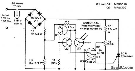
Projection lamp voltage regulator using a phototransistor, SOB and UJT (courtesy Motorola Semiconductor Products Inc.). (View)
View full Circuit Diagram | Comments | Reading(626)
Solid_state_relay_circuit_with_input_protection_of_the_MOC3011_triac_driver
Published:2009/7/21 7:41:00 Author:Jessie

Solid-state relay circuit with input protection of the MOC3011 triac driver. The input voltage to the protection circuit can be 3 to 30 volts DC (courtesy Motorola Semiconductor Products Inc.). (View)
View full Circuit Diagram | Comments | Reading(1316)
Remote_control_of_AC_load_using_an_MOC3011_optically_coupled_triac_driver
Published:2009/7/21 7:39:00 Author:Jessie
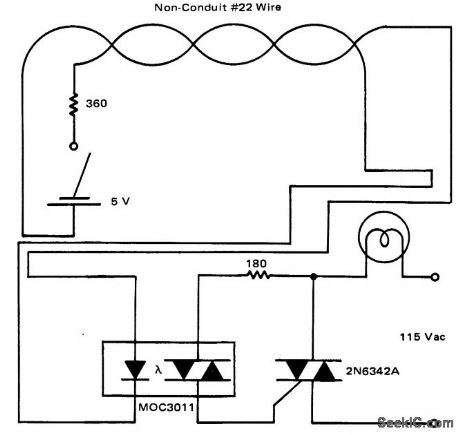
Remote control of AC load using an MOC3011 optically coupled triac driver (courtesy Motorola Semiconductor Products Inc.). (View)
View full Circuit Diagram | Comments | Reading(1218)
800_watt_triac_light_dimmer_with_silicon_bilateral_switch_SBS
Published:2009/7/21 7:38:00 Author:Jessie
800-watt triac light dimmer with silicon bilateral switch, SBS (courtesy Motorola Semiconductor Products Inc.). (View)
View full Circuit Diagram | Comments | Reading(2434)
Triac_control_circuit_with_current_boost_using_an_ECG776_zero_voltage_switch
Published:2009/7/21 7:27:00 Author:Jessie
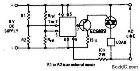
Triac control circuit with current boost using an ECG776 zero voltage switch. Resistor R2 must be the external sensor for the internal short and open protection to be operative. Notice that the circuit utilizes a DC supply. Select the triac for the particular application from the ECG5600 series (courtesy GTE Sylvania Incorporated). (View)
View full Circuit Diagram | Comments | Reading(1464)
800_watt_soft_start_triac_light_dimmer
Published:2009/7/21 7:26:00 Author:Jessie
800-watt soft-start triac light dimmer (courtesy Motorola Semiconductor Products Inc.). (View)
View full Circuit Diagram | Comments | Reading(3890)
| Pages:132/291 At 20121122123124125126127128129130131132133134135136137138139140Under 20 |
Circuit Categories
power supply circuit
Amplifier Circuit
Basic Circuit
LED and Light Circuit
Sensor Circuit
Signal Processing
Electrical Equipment Circuit
Control Circuit
Remote Control Circuit
A/D-D/A Converter Circuit
Audio Circuit
Measuring and Test Circuit
Communication Circuit
Computer-Related Circuit
555 Circuit
Automotive Circuit
Repairing Circuit