
power supply circuit
Index 120
200_V_D_C_TO_24_V_D_C_REGULATED_POWER_SUPPLY
Published:2009/7/20 4:53:00 Author:Jessie
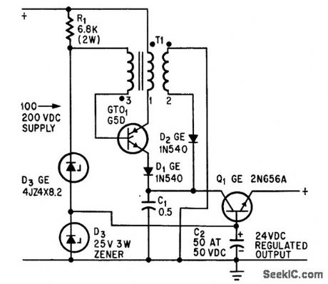
Gate turnoff and silicon power transistor together provide switching and regulating action efficiently at high frequency for d-c/d-c stepdown transformer applications.-D. R. Grafham, Now the Gale Turnoff Switch Speeds Up D-C Switching, Electronics, 37:12, p 64-71. (View)
View full Circuit Diagram | Comments | Reading(755)
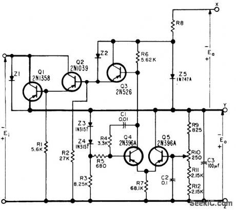
TEMPERATURE_STABILIZED_1_TO_17_V
Published:2009/7/20 4:59:00 Author:Jessie
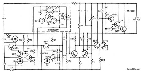
Shunttype supply uses prestabilizer to control temperature controller and stabiilzing circuit that serves as voltage reference. After reaching equilibrium temperature in 5 hours, overall drift over 15-hour period is only 36 microvolts per hour at 6 v output. Ripple voltage is 0.1 my maximum peak-to-peak.-E. Baldinger and W. Czaja, Designing Highly Stable Transistor Power Supplies, Electronics, 32:39, p 70-73. (View)
View full Circuit Diagram | Comments | Reading(634)
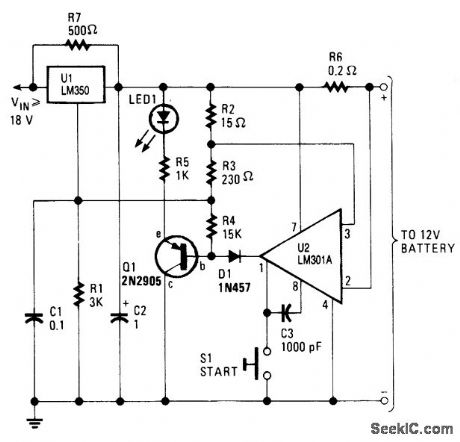
CHARGER_EXTENDS_LEAD_ACID_BATTERY_LIFE
Published:2009/7/9 20:32:00 Author:May
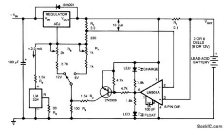
The circuit furnishes an initial charging voltage of 2.5 V per cell at 25'C to rapidly charge a battery. The charging current decrbases as the battery charges, and when the current drops to 180 mA, the charging circuit reduces the output voltage to 2.35 V per cell, floating the battery in a fully charged state. This lower voltage prevents the battery from overcharging, which would shorten its life. The LM301A compares the voltage drop across R1 with an 18-mV reference set by R2. The comparator's output controls the voltage regulator, forcing it to produce the lower float voltage when the battery-charging current pass-ing through RI drops below 180 mA. the 150-mV difference between the charge and float voltages is set by the ratio of R3 to R4. The LEDs show the state of the circuit. (View)
View full Circuit Diagram | Comments | Reading(1524)
EQUAL_POSITIVE_AND_NEGATIVE_VOLTAGES
Published:2009/7/20 4:58:00 Author:Jessie
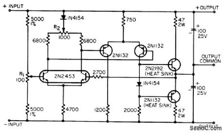
Single supply provides equal and opposite output voltages at desired value between 5 and 25 v, at up to 100 ma, for input voltages from 10 to 50 v. R1 balances output voltage, while R2 is adjusted to give good tracking of output voltage.-T. P. Sylvan, Regulator Makes Two Power Supplies Out of One, EEE, 14:5, p 117. (View)
View full Circuit Diagram | Comments | Reading(814)
+12_Vdc_MOBILE_BATTERY_CHARGER
Published:2009/7/9 20:28:00 Author:May
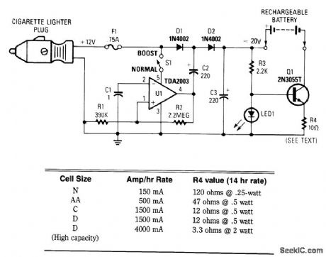
This circuit provides up to 20 V output from a 12-V automotive supply, to enable constant current charging of Nicad battery assemblies up to about 18 V total. V1 forms a square-wave oscillator, D1 and D2, coupling this square wave to the 12-V battery supply to obtain over 20 Vdc. If this is not needed, S1 is left open. Q1 forms a current regulator to determine the charging rate of the rechargeable battery. R4 is selected from the table or it can be switched with a rotary selector switch. (View)
View full Circuit Diagram | Comments | Reading(2457)
LINE_VOLTAGE_REGULATOR
Published:2009/7/20 4:46:00 Author:Jessie
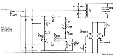
Line voltage controls frequency of relaxation oscillator Q3, which in turn changes triggering of scr's to keep load voltage essentially constant.-R Wechsler, Scr's Regulate A-C Line Voltage, ,. Electronics, 38:3, p 61-62. (View)
View full Circuit Diagram | Comments | Reading(911)
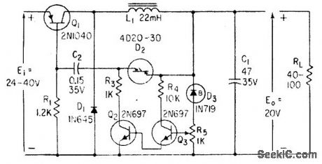
25_V_D_C_REGULATOR
Published:2009/7/20 4:43:00 Author:Jessie
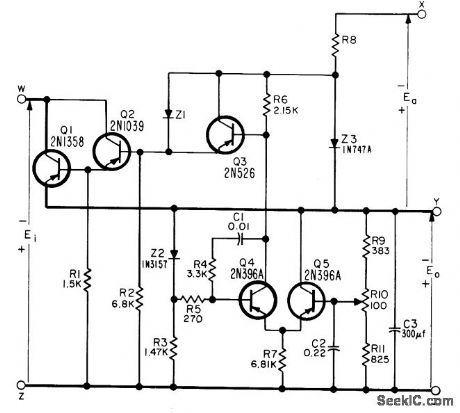
Provides up to 1.5 amp at 25 v with l% regulation for inputs of 26 to 50 v from unregulated source. Aux. iliary source Ea must be minimum of 5 v.-NBS, Handbook Preferred Circuits Navy Aeronautical Electronic Equipment, Vol. 11, Semiconductor Device Circuits, PSC 3, p 3.2. (View)
View full Circuit Diagram | Comments | Reading(711)
12_V_BATTERY_CHARGER
Published:2009/7/9 5:44:00 Author:May

This simple charger uses an LM350 regulator as a battery charger. (View)
View full Circuit Diagram | Comments | Reading(0)
CURRENT_LIMITED_6_V_CHARGER
Published:2009/7/9 5:44:00 Author:May
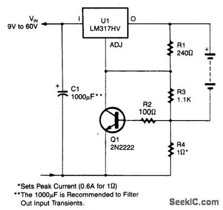
An LM317HV regulator is used as a current-limited charger. If current through R4 exceeds 0.6 A, Q1 is biased on, which pulls the ADJ terminal of the LM317 HV to ground and reduces the battery-charging current. (View)
View full Circuit Diagram | Comments | Reading(3207)
BATTERY_CHARGER
Published:2009/7/9 5:42:00 Author:May
This high-performance charger quickly charges gelled lead-acid batteries, and turns off at full charge. At first, the charge current is held at 2 A, but as battery voltage rises, current decreases. When current falls to 150 mA, the charger automat- ically switches to a lower float voltage to keep from overcharging. When you hit full charge, transistor Q1 lights the LED to indicate that status. (View)
View full Circuit Diagram | Comments | Reading(0)
50_V_D_C_REGULATOR
Published:2009/7/20 4:51:00 Author:Jessie
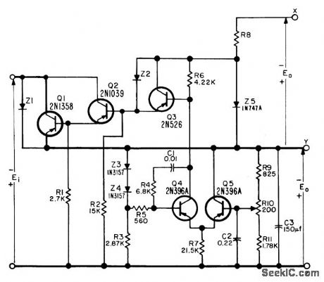
Provides up to 750 ma at 50 v with 1% regulation for inputs of 59 to 100 v from unregulated source. Auxiliary source Ea must be minimum of 5 v.-NBS; Handbook Preferred Circuits Navy Aeronautical Electronic Equipment, Vol. 11, Semiconductor Device Circuits, PSC 4, p 4-2. (View)
View full Circuit Diagram | Comments | Reading(694)
SUBAUDIBLE_TONE_ENCODER
Published:2009/7/20 4:50:00 Author:Jessie
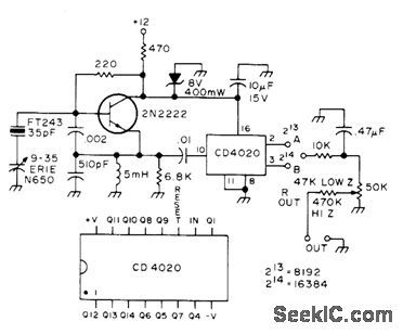
Simple crystal-controlled oscillator drives CD4020 CM0S divider to give output frequency below normal voice range, for providing tone access to repeater. With 1.120-MHz crystal and division ratio of 8192, output is 136.7 Hz. Output circuit is RC filter that converts square wave to triangle, with pot setting level. Article tells how to choose crystals for other output frequencies and division ratios.-C. Haines, Jr., Go Tone for Ten, 73 Magazine, Dec. 1976, p 22-23. (View)
View full Circuit Diagram | Comments | Reading(3931)
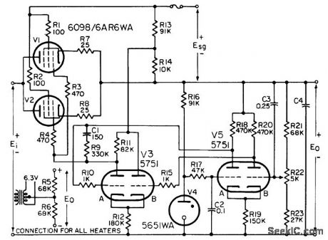
PREFERRED_150_V_D_C_REGULATOR
Published:2009/7/20 4:49:00 Author:Jessie
Provides either polarity of output with l% regulation, from minimum of 190 v d-c input. Maximum load current is 100 ma per series tube. C4 is minimum of 4 mfd.-NBS, Hand-book Preferred Circuits Navy Aeronautical Electronic Equipment, Vol. 1, Electron Tube Circuits, 1963, PC 4, p 4-2. (View)
View full Circuit Diagram | Comments | Reading(747)
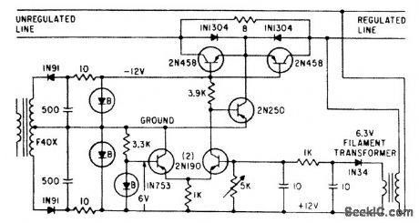
HEATER_VOLTAGE_REGULATOR
Published:2009/7/20 4:40:00 Author:Jessie
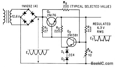
Clipping action is combined with depression of flat-top portion of output waveform in proportion to input voltage change, to hold rms output voltage constant within 0.2% of voltage determined by value of R5.-J. D. Wells, Low-Cost Adjustable Regulator Consumes Little Power, Electronics, 38:23, p 109-110. (View)
View full Circuit Diagram | Comments | Reading(814)
100_V_D_C_REGULATOR
Published:2009/7/20 4:39:00 Author:Jessie
Provides up to 400 ma at 100 v with 1% regulation for inputs of 101 to 150 v from unregulated source. Auxiliary source Ea must be minimum of 5 v.-NBS, Handbook Preferred Circuits Navy Aeronautical Electronic Equipment, Vol. 11, Semiconductor Device Circuits, PSC 5, p 5-2.
(View)
View full Circuit Diagram | Comments | Reading(760)
A_C_LINE_REGULATOR
Published:2009/7/20 4:26:00 Author:Jessie
Five-transistor circuit uses breakdown diodes to regulate voltage inputs between 113 v and 140 v to within 0.5 v of 110 v for 2-amp load.-R. A. Grainer, Line Voltage Control Uses Zener Diodes, Electronics, 33:6, p 64. (View)
View full Circuit Diagram | Comments | Reading(679)
as_CIRCUIT_LED_POWER_INDICATOR
Published:2009/7/9 5:21:00 Author:May
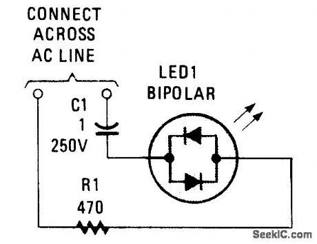
Many electronic circuits need an indication that they are under power; for most ac circuits, a neon lamp is the device of choice. A bidirectional tricolor LED can be used if a capacitor is connected in series with the LED to limit the current through the LED. A1-μF, 250-WVdc capacitor, which has a reactance of 2650 ohms at 60 Hz, is used in series with an LED to limit the current through the unit to 43 mA. The impedance of the LED is low compared to the reactance of the capacitor, so nearly al the impedance will be caused by the capacitor with the added advantage of no energy loss caused by the capacitor.
The power of the LED is 1.175Vx0.043 A=50 mW compared to an NE-2H at 250 mW. For 230V, use a 0.47-μF, 400-WVdc capacitor. (View)
View full Circuit Diagram | Comments | Reading(1073)
D_C_SWITCHED_REGULATOR
Published:2009/7/20 4:36:00 Author:Jessie
Gives 0.5% regulation for input voltage range from -15% to +30%. Efficiency is 95%. Transistor is near-ideal switch, having low leakage when open and low voltage when closed.-A. A. Sorenson, Solid-State D-C Switched Regulators, Electronics, 33:48, p 121-123. (View)
View full Circuit Diagram | Comments | Reading(723)
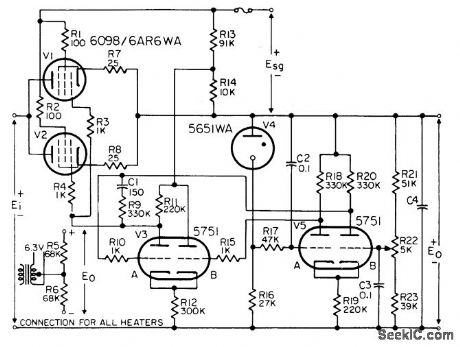
PREFERRED_01_REGULATION_300_V_D_C
Published:2009/7/20 4:32:00 Author:Jessie
Provides either polarity, for applications requiring superior regulation and long-time stability Minimum input is 340 v d-c, and -minimum Esg is 150 v. Maximum load current is 100 ma per series tube. C4 is minimum of 4 mfd.-NBS, Handbook Preferred Circuits Navy Aeronautical Electronic Equipment, Vol. 1, Electron Tube Circuits, 1963 PC 5, p 5-2. (View)
View full Circuit Diagram | Comments | Reading(638)
3_30_V_UNIVERSAL_POWER_SUPPLY_MODULE
Published:2009/7/9 5:05:00 Author:May
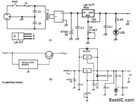
U1, an LM317 adjustable regulator provides short-circuit protection and automatic current limiting at 1.5 A. The input voltage to the regulator is supplied by DB1, a 4-A 100 PIV full-wave bridge rectifier. Capacitor C1 provides initial filtering. U1 provides additional electronic filtering as part of the regulating function. The output level of the regulator is set by trimpot R1. Bypass capacitors on the input and output of U1 prevent high-frequency oscillation. The current rating of the transformer must be at least 1.8 times the rated continuous-duty output of the supply. This means that a 1.5-A supply should use a 2.7-A transformer. For light or intermittent loads, a smaller 2.0-A transformer should suffice.Wiring a second LM317, U2, in parallel with U1 is a quick and clean way to increase the current-limiting threshold to 3 A without sacrificing short-circuit protection. When more than 3 A is required, the regulator module can be used to drive the base of one or more pass-transistors (see Fig. 75-2B).
A simple battery-powered switching regulator provides 5 V out from a 9-V source with 80% efficiency and 50 mA output capability. When Q1 is on, its collector voltage rises, forcing current through the inductor. The output voltage rises, causing A1's output to rise. Q1 cuts off and the output decays through the load. The 100-pF capacitor ensures clean switching. The cycle repeats when the output drops low enough for A1 to turn on Q1. The 1-μF capacitor ensures low battery impedance at high frequencies, preventing sqg during switching. (View)
View full Circuit Diagram | Comments | Reading(1605)
| Pages:120/291 At 20101102103104105106107108109110111112113114115116117118119120Under 20 |
Circuit Categories
power supply circuit
Amplifier Circuit
Basic Circuit
LED and Light Circuit
Sensor Circuit
Signal Processing
Electrical Equipment Circuit
Control Circuit
Remote Control Circuit
A/D-D/A Converter Circuit
Audio Circuit
Measuring and Test Circuit
Communication Circuit
Computer-Related Circuit
555 Circuit
Automotive Circuit
Repairing Circuit