
power supply circuit
Index 102
AUDIO_INTERPOLATING_PHASE_SHIFTER
Published:2009/7/17 3:03:00 Author:Jessie
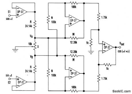
A simple interpolating phase shifter places a negative resistance across potentiometer X to obtain constant-amplitude, linear-phase performance. (View)
View full Circuit Diagram | Comments | Reading(763)
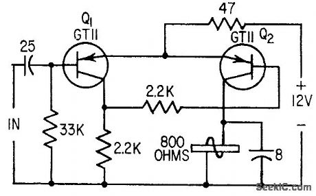
CABLE_DRIVE_FOR_VELOCIMETER
Published:2009/7/17 3:02:00 Author:Jessie
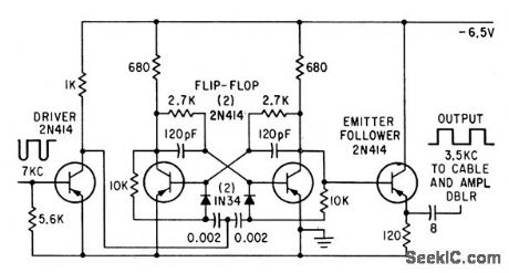
Flip-flop frequency divider converts 7-kc pulse output of velocimeter to 3.5 kc while providing low impedance and sufficient driving power for sending pulses through up to 35,000 feel of cable to counter on surface vessel.-L. Dulberger, Deep-Ocean Velocimeter Aids Sonar Systems Design, Electronics, 34:22, p 41-43. (View)
View full Circuit Diagram | Comments | Reading(963)
SIMPLE_REMOTE_CONTROL_INTERFACE_CIRCUITS
Published:2009/7/17 4:11:00 Author:Jessie
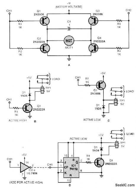
If you want to control a dc motor, a momentary load, or an on/off load, these are some useful interface circuits. Figure A shows a dc-motor controller that requires the outputs of two different channels (CH1 and CH2). Note that it doesn't matter if the channel outputs are active low or high; what matters is that CH1 must be different from CH2 for the motor to be energized. The circuits in Figs. B and C are momentary-load controllers for active high and active low channel outputs, respectively. The circuit in Fig. D is a toggled-load controller. If you have an active high channel out-put, you must add the inverter shown. (View)
View full Circuit Diagram | Comments | Reading(1023)
Free_running_multivibrator_using_an_ECG955M_timer_oscillator_chip
Published:2009/7/17 4:10:00 Author:Jessie
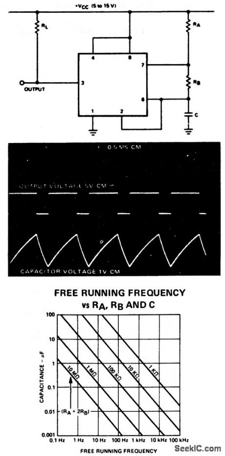
Free-running multivibrator using an ECG955M timer/oscillator chip. The external capacitor charges through RA and RB, but discharges through RB only. The photo shows the actual waveforms generated. The free-running frequency can be easily found by referring to the graph (courtesy GTE Sylvania Incorporated).
(View)
View full Circuit Diagram | Comments | Reading(702)
IMPROVED_ONE_SHOT
Published:2009/7/17 4:10:00 Author:Jessie
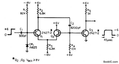
Improvement of basic circuit uses less power and fewer components, while providing higher timing accuracy.-T. G.. Ellestad, Improved One-Shot Output Circuits, EEE, 13:8, p 67. (View)
View full Circuit Diagram | Comments | Reading(693)
AUTOMATIC_WATERING_SYSTEM_CONTROLLER
Published:2009/7/17 4:10:00 Author:Jessie
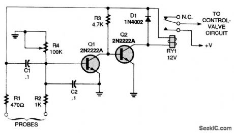
Two probes are inserted into the soil. When the soil is wet, it is more conductive and Q1 is for-ward-biased, cutting Q2 off. As the soil dries, Q1 loges bias, allowing Q2 to turn on, actuating the relay RY1. RY1 closes, operating the watering-system control valve. When the soil is sufficiently moist, Q1 turns on, cutting off Q2, RY1, and the water valve. (View)
View full Circuit Diagram | Comments | Reading(1172)
MULTIVIBRATOR_CONTROLLED__RELAY
Published:2009/7/17 4:09:00 Author:Jessie
Control signal is used to trigger mvbr that operates relay when input signal is greater than predetermined level (about 10 mv), and releases relay immediately when signal falls below this level.-G. B. Miller, Multivibrator Operates Relay, Electronics, 31:49, p 106-112. (View)
View full Circuit Diagram | Comments | Reading(666)
SPRINKLER_GUARDIAN_
Published:2009/7/17 4:09:00 Author:Jessie
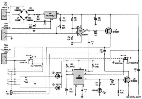
The Sprinkler Guardian can be used in conjunction with any sprinkler controller that uses standard 24-Vac valves. The add-on unit senses the moisture content at the ground surface; if the ground is dry, the unit allows the controller to execute all the ON times preset by the controller clock. The unit obtains its power supply from the controller that it is used with. The output of U1 supplies a regulated 12 V to the rest of the circuit. The ground probes are connected to terminals 1 and 2 of TB2. Resistor R2 is used to balance the resistance of the earth between the two probes so that op amp U2, which is configured as a comparator, outputs a high when the ground is dry. PNP transistor Q1 is turned off, K1 is not energized, and terminals 1 and 2 of TB3 are shorted. Under those con-ditions, if the controller calls for watering the lawn, watering will commence. Now, assume that the ground is wet. The resistance between the probes drops, causing the output of U2 to go low, which turns on Q1. That energizes K1. Under those conditions, even when the controller is programmed to water, the valves will not open. Now assume that the soil is dry. Relay K1 is off. When the programmed watering time arrives, the water valve is opened, starting the timed watering cycle. The probes are wetted immediately, and U2 goes low. As the voltage output of U2 drops, a negative-going pulse is delivered through C4 to pin 2 of U3, a 555 timer, which triggers the timer into operation. The time output from pin 3 turns Q2 off, which keeps K1 from closing during the time cycle deter-mined by R8 and C7. That allows time for the sprinkler system to complete the watering cycle. A DPDT switch, S1, is used to place the circuit in either the automatic or manual mode. In the automatic mode, the circuit operates as previously described. In the manual mode, the terminals of TB3 are shorted, effectively removing the Guardian from the system. (View)
View full Circuit Diagram | Comments | Reading(1276)
SCR_gas_smoke_detector_with_half_wave_control_of_24_volt_AC_horn
Published:2009/7/17 4:02:00 Author:Jessie
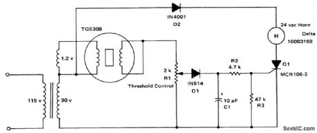
SCR gas/smoke detector with half-wave control of 24-volt AC horn. The Taguchi gas sensor (TGS) consists of an N-type semiconductor of tin dioxide encased in a noble metal wire heater, which also serves as an electrode (courtesy Motorola Semiconductor Products Inc.). (View)
View full Circuit Diagram | Comments | Reading(1573)
AC_OPERATED_WATERING_CONTROL_SYSTEM
Published:2009/7/17 4:02:00 Author:Jessie
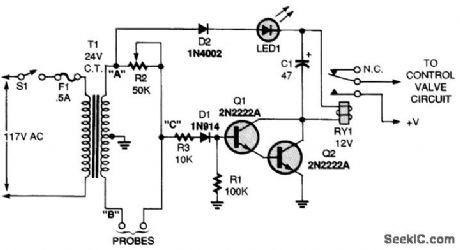
Ac operation of the circuit reduces possible electrolysis effects over time. Two probes are inserted into the soil. When the soil is wet, it is more conductive and Q1 conducts, cutting Q2 off. As the soil dries, Q1 loses bias, allowing Q2 to turn on, actuating the relay (RY1). RY1 closes, operating the watering-system control valve. When the soil is sufficiently moist, Q1 turns on, cutting off Q2, RY1, and the water valve. R2 sets the trip level. (View)
View full Circuit Diagram | Comments | Reading(864)
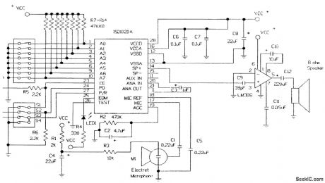
1_min_RECORD_PLAYBACK_CIRCUIT
Published:2009/7/17 4:02:00 Author:Jessie
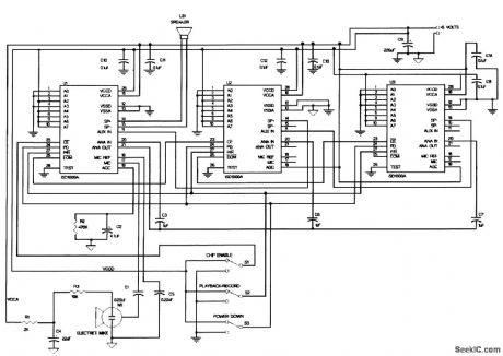
You can cascade several ISD1020As to increase a system's capacity. A circuit to create a 1-minute message is shown. With this conftguration, a message is stored across chip boundaries in a manner transparent to the user. Changing from Record to Play resets the MSP to the beginning of the first message in the series. The next Play proceeds under control of CB. The circuit operates exactly like that for a single device. (View)
View full Circuit Diagram | Comments | Reading(842)
TAPELESS_PLAY_ONLY_DEVICE
Published:2009/7/17 4:01:00 Author:Jessie
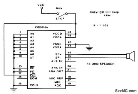
This requires a prerecorded message to be preprogrammed in the ISD1020A. To play a message, set the switch to the +5-V position. The ISD1020A plays the entire contents one time, then stops.Because CB is tied low, the set end-of-message bits are ignored. Momentarily changing the switch to open, then back to +5 V makes the ISD1020A play again. (View)
View full Circuit Diagram | Comments | Reading(1071)
Tri_level_comparator
Published:2009/7/17 4:01:00 Author:Jessie
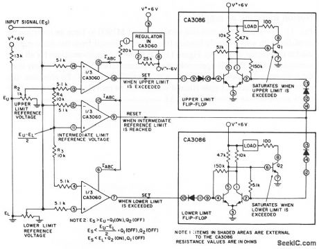
This circuit uses all three sections of a CA3060 to form a tri-level comparator, which has three adjustable limits. If either the upper or lower limit is exceeded, the appropriate output is activated until the input signal returns to a selected intermediate value. Such comparators are used in industrial control applications. The lower and upper limits are set by R 1 and R2, respectively. R3 and R4 set the intermediate limit. When both R3 and R4 are the same value, the intermediate limit is midway between the upper and lower limits. The loads shown are 5-V 25-mA lamps. Harris Semiconductor Linear & Telecom ICs 1991 p 3-51 (View)
View full Circuit Diagram | Comments | Reading(2577)
FAULT_TOLERANT_RELAY_DRIVER
Published:2009/7/17 4:09:00 Author:Jessie
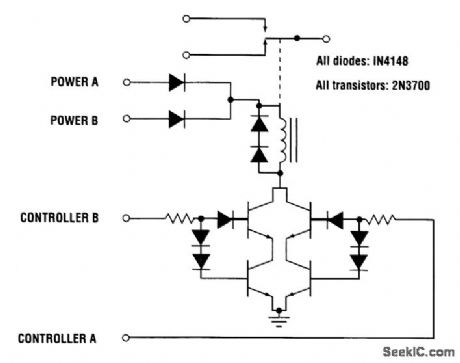
Mechanical relays are useful in remote-switching applications that require electrical isolation between control and switched circuits. The traditional approach for driving the relay coils uses a single-transistor common-emitter switch. The figure shows a circuit that can reduce the likelihood of having an unrecoverable failure in the relay driver circuit. Additional transistor switches, inserted in series with the original controlling transistors, maintain proper operation if a single transistor fails. The diodes connected to the upper transistors prevent reverse base-current flow if the collector-base junctions break down. The diodes connected to the lower transistor provide proper biasing for the circuit. The upper and lower transistors will have a similar Vbe because they are the same type and have nearly identical currents. Therefore, the Vbe of the lower transistor will be about the same as one diode voltage drop, and the device will be operating in the active region. Power to the relays can be provided by one of two voltage sources connected together through 'diodes in a wired-OR configuration. The additional diode clamps the coil inductance voltage spike in the event that one of the suppression diodes fails shorted. (View)
View full Circuit Diagram | Comments | Reading(2631)
SOLID_STATE_LATCHING_RELAY_CIRCUIT
Published:2009/7/17 4:07:00 Author:Jessie
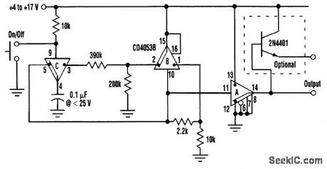
A multitude of simple circuits perform switch debouncing because there are many ways to implement a toggling latch. The circuit illustrated here merges these functions into one topology, is extremely tolerant of power-supply variation (it works fine over more than a 3:1 range of supply voltage), and, most importantly, is unusual. The IC used in this case is the 4053B triple CMOS SPDT switch. Section B acts as a bistable latch and stores the current ON/OFF state of the relay. The 2.2-kΩ resistor between pins 1 (the ON terminal of the switch) and 10 (the control input) provides positive feedback that sustains the switch in whichever state it finds itself. Thus, if the latch is ON, pin 1 will be switched to pin 15 and, thereby, the positive rail. This will reinforce the positive state of pin 10 and the ON state of the switch. If, on the other hand, the latch is OFF, then the connection of pin 1 to pin 15 will be broken and the 10-kΩ pull-down resistor will drag pin 1 to ground. This will pull pin 10 low, in turn, holding the latch in the OFF state. Meanwhile, pin 2 will output the logic inverse of the signal appearing in pin 1. This signal communicates to pin 3 and, if the control push button is open, will connect to pin 4 and charge the capacitor to a state opposite that of the latch. There matters will rest until someone presses the button. This will connect the capacitor to pin 10 and toggle the Latch state. 4053B section A serves as an output buffer and has an output impedance of about 200 Ω when run with a 5-V supply and 100 Ω when run with a 12-V supply. If this is insufficient for the application, a transistor emitter-follower, like that illustrated, will boost output capability to beyond 0.1 A. (View)
View full Circuit Diagram | Comments | Reading(2583)
POLARITY_SENSITIVE_RELAY_CIRCUIT
Published:2009/7/17 4:07:00 Author:Jessie
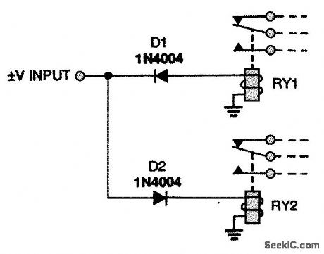
When a positive voltage is input to the circuit, relay RY1 is activated; when a negative voltage is input, RY2 is activated. (View)
View full Circuit Diagram | Comments | Reading(1639)
Ionization_chamber_smoke_detector_using_McMOS_alarm_oscillators_
Published:2009/7/17 4:07:00 Author:Jessie
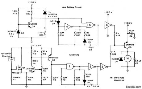
Ionization-chamber smoke detector using McMOS alarm oscillators (courtesy Motorola Semiconductor Products Inc.). (View)
View full Circuit Diagram | Comments | Reading(2831)
50_μA_SOLID_STATE_RELAY
Published:2009/7/17 4:06:00 Author:Jessie


The relay circuit described here reduces the control current to 50 μA, but can switch up to 600 W of 120-Vac power. The circuit uses a conventional 10-A, 400-V triac. The triac gate current is routed through a small bridge rectifier, a 15-V zener diode, a sensitive SCR (Q2), and a 180-Ω resistor (R2). The circuit allows a small SCR to control ac current through the triac's gate terminal. The voltage needed to control the SCR's gate terminal is developed by rectifying and filtering the ac voltage across the triac. Capacitors C2, C4, and C5, resistor R3, bridge rectifier BR2, and zener diode D2 form the rectifier circuit. C5 and D2 filter and limit the supply voltage to about 8 V, while the 470-Ω resistor R3 limits the charging current. To develop a slightly higher voltage (up to 30 V p-p), a 15-V zener diode (D1) is inserted in series with the SCR. D1 delays the triac's conduction trigger point each half cycle and produces only a slight reduction in rms power to the load. The dc control voltage, produced by the rectifier circuit, is switched to the SCR's gate using a sensitive Darlington-type optoisolator (A1)i Only about 50 μA of LED current in the isolator is needed to fully turn on the SCR. (View)
View full Circuit Diagram | Comments | Reading(1005)
TRANSISTOR_UJT_MVBR
Published:2009/7/17 4:06:00 Author:Jessie
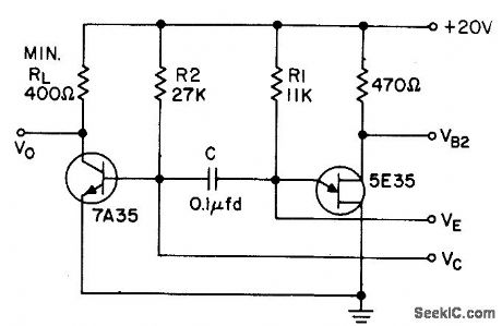
Uses low-cost 7A35 silicon mesa transistor.- Transistor Manual, Seventh Edition, General Electric Co, 1964, p 341. (View)
View full Circuit Diagram | Comments | Reading(626)
TGS_gas_smoke_detector_with_2_minute_time_delay_using_a_McMOS_latch_
Published:2009/7/17 4:05:00 Author:Jessie
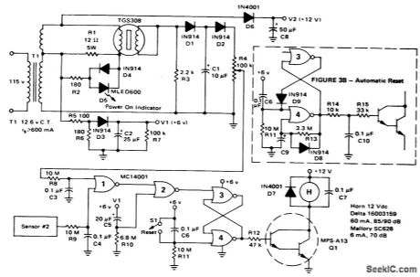
TGS gas/smoke detector with 2-minute time delay using a McMOS latch (courtesy Motorola Semiconductor Products Inc.). (View)
View full Circuit Diagram | Comments | Reading(818)
| Pages:102/291 At 20101102103104105106107108109110111112113114115116117118119120Under 20 |
Circuit Categories
power supply circuit
Amplifier Circuit
Basic Circuit
LED and Light Circuit
Sensor Circuit
Signal Processing
Electrical Equipment Circuit
Control Circuit
Remote Control Circuit
A/D-D/A Converter Circuit
Audio Circuit
Measuring and Test Circuit
Communication Circuit
Computer-Related Circuit
555 Circuit
Automotive Circuit
Repairing Circuit