
power supply circuit
Index 112
0_66V_AT_2A
Published:2009/7/19 21:24:00 Author:Jessie
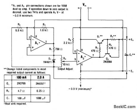
High-power circuit is suitable for low-voltage logic devices that require high current at supply voltages between 3 and 6V. Maximum output of 2A is obtained with 2N6057 Darlington pair for Q1. Single 2N3766 can be used if load is only 100mA. Q2 provides short-circuit protection for Q1, Since supply does not have to be adjusted down to 0V,negative supply for A2 can go to common negative of circuit. Optional connection to -3 V is used only when voltage range must go down to 0V.-W.G. Jung, IC Op-Amp Cookbook, Howard W. Sams, Indianapolis, IN, 1974, p 157-158. (View)
View full Circuit Diagram | Comments | Reading(823)
Precision_current_sourced_VFC
Published:2009/7/19 21:23:00 Author:Jessie
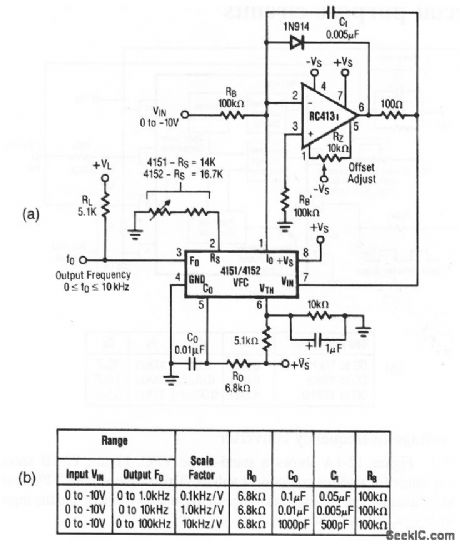
Figure 12-2A shows a current-sourced VFC that is similar to Fig. 12-1, except that the passive RC integrator is replaced by an active op-amp integrator.This increases the dynamic range down to 0 V, improves response time, and eliminates the nonlinearity error that is introduced by the limited compliance of the switched current source output. Figure 12-2B shows the operating range for various component values. Raytheon Linear Integrated Circuits 1989 p 7-7, 7-8. (View)
View full Circuit Diagram | Comments | Reading(717)
NEUTRON_DIFFRACTOMETER
Published:2009/7/19 21:23:00 Author:Jessie
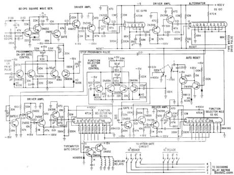
Neutron beam from reactor strikes sample, producing diffraction pattern. Multielement glow tubes control sequence of operation in which length of data accumulation time at each angle of diffraction is determined by counting neutrons in incident beam. This eliminates counting errors due to reactor level fluctuations. Circuit drives key solenoids of electric type-writer to give printout of results.-E. W. Johanson, Glow-Tube Programmer Controls Neutron Spectrometer Experiments, Electronics, 34:19, p 65-67. (View)
View full Circuit Diagram | Comments | Reading(740)
LOW_OHMS_ADAPTER
Published:2009/7/10 3:53:00 Author:May
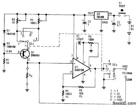
The circuit consists of a 5-V regulator, constant-current source D1, D2, and Q1, and op amp gam stage U1. Power is provided by a 9-V battery whose output is regulated to + 5 Vdc by the 3-terminal regu-lator. The emitter of Q1 is always 0.6 V below the + 5-V line. Resistor R1 sets the current through both diodes D1 and D2 to 5mA.
The resulting 0.6 Vdc across one of the multiturn trimmer potentiometers (R2 and R3), as selected by switch section S2A, sets the current through Q1 and the resistor-under-test.
When R2 is selected, the test current is 1mA; when R3 is selected, the test current is 10mA. On the lower two ranges, ×1 and ×10, the voltage across resistance-under-test is applied directly to the DMM terminals. On the upper two ranges, op amp gain stage UI is switched into the circuit and the DMM mea-sures the voltage between op amp output pin 6 and the test resistor.
When switch S2 is in position 3 (× 100) the current set by the constant-current source is 1 mA; the multiplying factor is ×100. When S2 is in position 4, ×1 000, the current is 10 mA and the multiplying factor is 100 x 10 = 1 000. Multiturn trimmer-potentiometer R6 adjusts the offset of the op amp so that, with no voltage across the resistor-under-test (i.e. with the measurement terminals short-circuited), the output is zero. (View)
View full Circuit Diagram | Comments | Reading(1065)
NEGATIVE_SHUNT_REGULATION
Published:2009/7/19 21:22:00 Author:Jessie
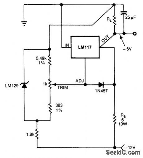
Connection shown for LM117 positive series regulator provides spike-suppressing negative shunt regulation of -5V output With capacitor shown, regulator will withstand 75-V spikes on raw DC supply For larger spikes, increase capacitor value.-P Lefferts, Series Regulators Provide Shunt Regulation, EDN Magazine, Sept 5,1978,p158 and 160. (View)
View full Circuit Diagram | Comments | Reading(797)
Basic_voltage_to_frequency_converter
Published:2009/7/19 21:22:00 Author:Jessie
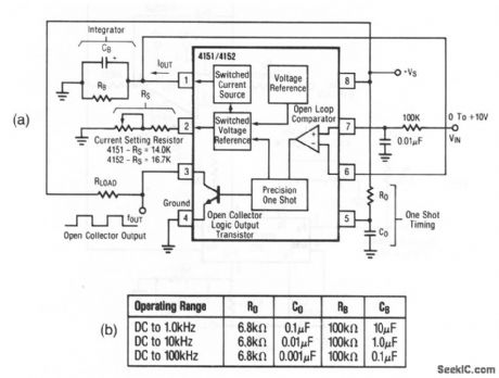
Figure 12-1A shows a stand-alone VFC. Figure 12-1B shows the operating range for various component values. This single-supply VFC is recommended for uses, where the dynamic range of the input is limited, and the input does not reach 0 V. Raytheon Linear Integrated Circuits, 1989 p 7-6 7-7 (View)
View full Circuit Diagram | Comments | Reading(746)
5V_AT_5A_FOR_TTL
Published:2009/7/19 21:21:00 Author:Jessie
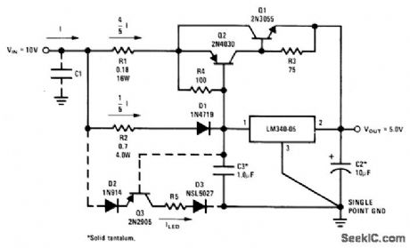
Typical load regulation is 1.8% from no load to full load, Q1 and Q2 serve in place of single higher-cost power PNP boost transistor. Dotted lines show how to add overload indicator using National NSL5027 LED and R2 as overload sensor. When load current exceeds 5A, Q3 turns on and D3 lights. Circuit includes thermal shutdown and short-circuit protection.- Linear Applications, Vol. 2, National Semiconductor, Santa Clara, CA, 1976, AN-103, p 5. (View)
View full Circuit Diagram | Comments | Reading(940)
±5_AND±12_V_FOR_COMPUTER
Published:2009/7/19 21:20:00 Author:Jessie
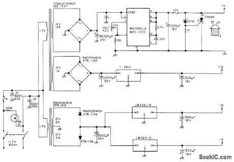
Provides all voltages required for 8080-4BD microcomputer system marketed by The Digital Group (Denver, CO). Transformer for positive supplies is 6.3-V 20-A unit with secondary replaced by two new windings giving required voltage and current. Crowbar circuit using 2N688 SCR protects ICs in memory and CPU. Use of at feast 50,000 μF in filter of 5-V supply prevents noise problems in computer MPC-1000 5-V 10-A regulator should be mounted on large heatsink at rear of computer housing in open air.- L.I. Hutton, A Ham's Computer, 73 Magazine, Dec. 1976, p78-79 and 82-83. (View)
View full Circuit Diagram | Comments | Reading(917)
THERMAL_NUCLEAR_RADIATION_DETECTOR
Published:2009/7/19 21:19:00 Author:Jessie
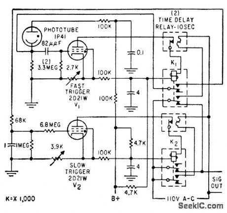
Triggers only on Light lash from nuclear explosion, consisting of initial fast-rising pulse lasting a few millisec, followed by pulse lasting over 1 sec. Discriminates against short lashes from lightning and shell bursts, and long slowly rising pulses caused by headlights and sunlight reflections.-J. C. Champeny, T. E. Petriken, and S. Siciliano, Nuclear Bomb Alarm Systems, Electronics, 32:19, p 53-55. (View)
View full Circuit Diagram | Comments | Reading(1479)
JUNCTION_DIODE_ALPHA_DETECTOR
Published:2009/7/19 21:15:00 Author:Jessie
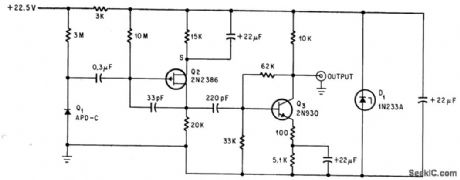
Used for counting alpha particles at high altitudes in dew-point hygrometer. Signal-to-noise ratio is poor (about 4 to 1).-C. R. Seashore and C. D, O'Brien, FET Detects Alpha Particles Better and More Precisely, Electronics, 38:3, p 64-66. (View)
View full Circuit Diagram | Comments | Reading(959)
TRANSISTORIZED_GEIGER_COUNTER
Published:2009/7/19 21:14:00 Author:Jessie
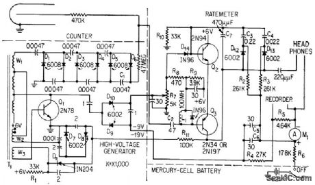
Rate-meter circuit converts output of halogen-type counter directly into meter indication corresponding to radiation intensity. Counter triggers two-transistor switch to place low-impedance load across conventional dual-output diode pump. Two halves of pump current are summed in metering circuit.-F. S. Goulding, Transistorized Geiger Counter Fits in Probe, Electronics, 32:3, p 64-66. (View)
View full Circuit Diagram | Comments | Reading(2188)
0_TO_±15V_TRACKING_AT_100mA_OR_2A
Published:2009/7/19 21:09:00 Author:Jessie
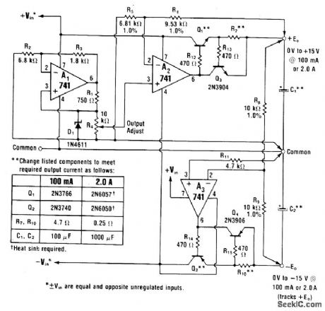
Basic tracking regulator is combined with transistors to extend output to voltages higher than zener reference and provide higher output currents. Choice of transistors for Q1 and Q2 determines maximum load current.-W. G. Jung, IC Op-Amp Cookbook, Howard W. Sams, indi-anapolis, IN, 1974, p 161-163. (View)
View full Circuit Diagram | Comments | Reading(841)
Multimeter_single_chip
Published:2009/7/19 21:49:00 Author:Jessie
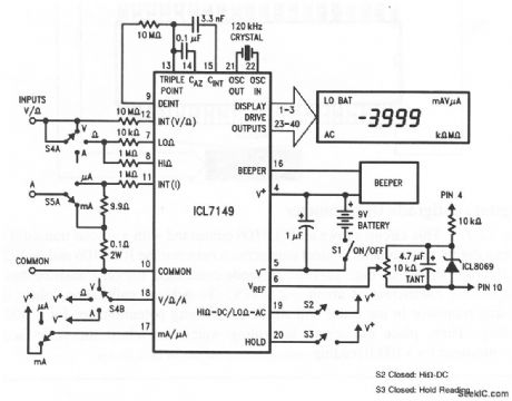
This circuit shows an ICL7149 that is connected as a low-power, autoranging digital multimeter. Although the ohms ranges do not need protection, the current ranges should be provided with fast-blow fuses between 55A and the 0.1- and 9.9-Ω shunt resistors. Also, the 10-kΩ resistor at pin 7 must be able to dissipate 1.2 or 4.8 W for short periods during accidental application of 110- or 220-V line voltages, respectively. The suggested crystal is a Statek CX-1V, the display is an LXD part number 38D8R02H, and the beeper is a muRata PKM24-4A0. (View)
View full Circuit Diagram | Comments | Reading(4311)
COLD_CATHODE_COUNT_RATE_CIRCUIT
Published:2009/7/19 21:48:00 Author:Jessie

Fourelement cold-cathode tube operates directly from output pulse of 6292 photomultiplier receiving light output of Zns screen of alpha particle detector. Maximum counting rate is 100 counts per second.-M. H. Goosey, De-signing Cold-Cathode Tube Circuits, Electron-ics, 31:3, p 101-108. (View)
View full Circuit Diagram | Comments | Reading(660)
A_D_conversion_and_display_for_ac_signals
Published:2009/7/19 21:46:00 Author:Jessie
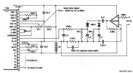
This circuit shows an ICL7106 connected to measure ac voltages, and to display the results on a 3 1/2-digit LCD. Direct connections between the ICL7106 and an LCD display are shown in Fig. 12-11B. Adjust the 1-kΩ potentiometer for the desired scale factor. Harris Semiconductors Data Acquisition, 1991 p 2-40 (View)
View full Circuit Diagram | Comments | Reading(854)
FET_ALPHA_DETECTOR
Published:2009/7/19 21:45:00 Author:Jessie
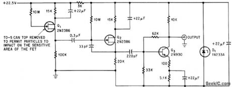
Field-effect transistor with cover removed serves as low-noise alpha-particle detector in high-altitude dew point hygrometer. Signal-to-noise ratio is 67 to 1.-C. R. Seashore and C. D. O’Brien, FET Detects Alpha Particles Better And More Precisely, Electronics, 38:3, p 64-66. (View)
View full Circuit Diagram | Comments | Reading(1576)
46_60V_FROM_62V
Published:2009/7/19 21:45:00 Author:Jessie
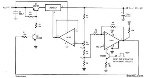
Variable-output high-voltage regulator includes short-circuit and overvoltage protection. When LM340K-24 regulator has been shut down by shorted load, LM311 must be activated by applying 4-V strobe pulse to 2N2222 transistor to make Q1 close again and start regulator.-' Linear Applications, Vol. 2, National Semiconductor, Santa Clara, CA, 1976, AN-103, p 11-12. (View)
View full Circuit Diagram | Comments | Reading(1332)
Digital_centigrade_thermometer
Published:2009/7/19 21:44:00 Author:Jessie
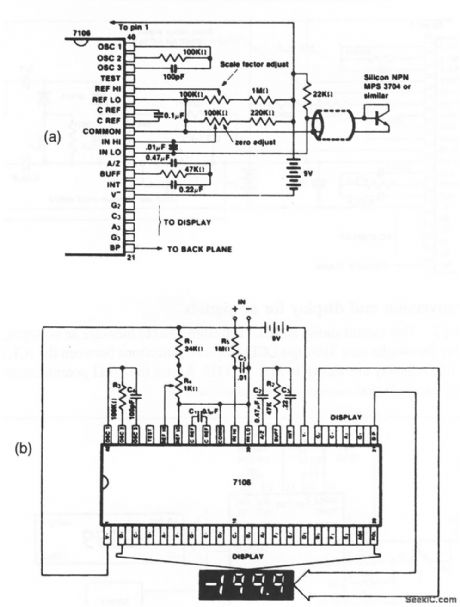
This circuit shows an ICL7106 connected with a silicon transistor to form a digital thermometer. Direct connections between the ICL7106 and an LCD display are shown in Fig. 12-11B. A diode-connected silicon transistor has a temperature coefficient of about -2 mV/℃. To achieve calibration, place the sensing transistor in ice water and adjust the zeroing potentiometer for a 000.0 reading. Then, place the sensor in boiling water and adjust the scale-factor potentiometer for a 100.0 reading. Bards Semiconductors Data Acquisition, 1991 p 2-32, 2 39 (View)
View full Circuit Diagram | Comments | Reading(1709)
15V_AT_1A_WITH_LOGIC_SHUTDOWN
Published:2009/7/19 21:43:00 Author:Jessie
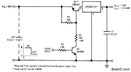
Arrangement shown provides practical method d shutting down LM340T-15 or similar regulator under control of ff L or DTL gate. Pass transistor Q1 operates as saturated transistor when logic input is high (2.4 V minimum for TTL) and Q2 is turned on. When logic input is low (below 0.4 V for TTL), Q2 andQ1 are off and regulator is in effect shut down.- Linear Applications, Vol.2, National Semiconductor, Santa Clara, CA, 1976, AN.103, p 11. (View)
View full Circuit Diagram | Comments | Reading(1452)
SIX_TRANSISTOR_6_V_BROADCAST_RECEIVER
Published:2009/7/20 0:50:00 Author:Jessie
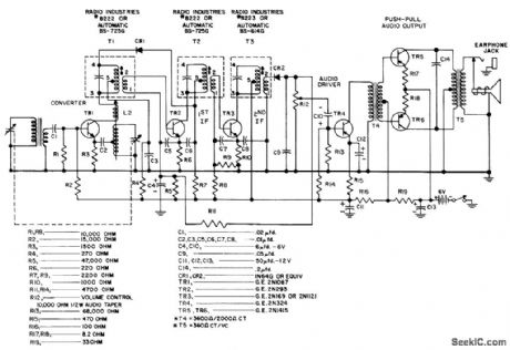
Nominal sensitivity is 200 microvolts per meter, maximum power output is 200 mw, and zero-signal battery drain is 8 ma.- Transistor Manual, Seventh Edition, General Electric Co., 1964, p 292. (View)
View full Circuit Diagram | Comments | Reading(760)
| Pages:112/291 At 20101102103104105106107108109110111112113114115116117118119120Under 20 |
Circuit Categories
power supply circuit
Amplifier Circuit
Basic Circuit
LED and Light Circuit
Sensor Circuit
Signal Processing
Electrical Equipment Circuit
Control Circuit
Remote Control Circuit
A/D-D/A Converter Circuit
Audio Circuit
Measuring and Test Circuit
Communication Circuit
Computer-Related Circuit
555 Circuit
Automotive Circuit
Repairing Circuit