
power supply circuit
Index 114
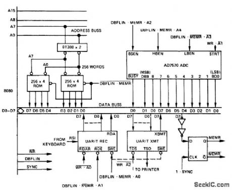
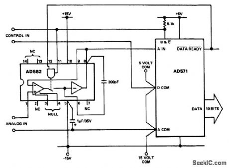
10_bit_A_D_converter_interface_with_an_8_bit_bus_such_as_in_the_8080_control_structure
Published:2009/7/19 22:17:00 Author:Jessie
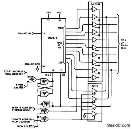

10-bit A/D converter interface with an 8-bit bus such as in the 8080 control structure (courtesy Analog Devices, Inc.). (View)
View full Circuit Diagram | Comments | Reading(1281)
±65V_TRACKING_AT_1A
Published:2009/7/19 22:16:00 Author:Jessie
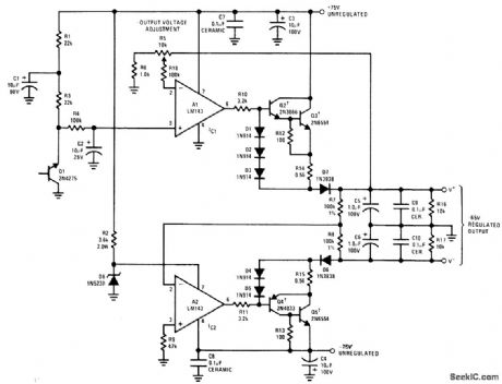
Circuit uses two LM143 high-voltage opamps in combination with zener reference and discrete power-transistor pass elements.Q1 is transistor used as stable 6.5-V zener voltage reference. Opamp A1 amplifies reference voltage from 1 to about 10 times for application through R10 to Darlington-connected transistors Q2 and Q3. Feedback resistor R5 is made variable so positive output voltage can be varied from 6.5 V to about 65 V. This output is applied to unity-gain inverting power opamp A2 to generate negative output voltage. Q2-Q5 should be on common Ther-malloy 6006B or equivalent fleatsink. Supply includes short-circuit protection. Maximum shorted load current is about 1.25 A.- Linear Applications, Vol. 2, National Semiconductor, Santa Clara, CA, 1976, AN-127, p 8-9. (View)
View full Circuit Diagram | Comments | Reading(922)
Cold_junction_compensation_for_type_K_thermocouple
Published:2009/7/19 22:16:00 Author:Jessie
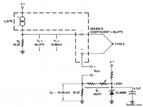
This circuit shows an AD590 that is connected to compensate a type-K thermocouple. The reference junctions should be in close thermal contact with the AD590 case. V+ must be at least 4 V and ICL8069 current should be set at 1 to 2 mA. Calibration does not require shorting or removal of the thermocouple. Set R1 for V2= 10.98 mV. If very precise measurements are needed, adjust R2 to the exact Seebeck coefficient for the thermocouple used (measured or from table), then note V1 and set R1 to buck out this voltage (that is, set V2 to equal V1). For other thermocouple types, adjust values to the appropriate Seebeck coefficient. (View)
View full Circuit Diagram | Comments | Reading(1744)
SATELLITE_TRANSMITTER
Published:2009/7/19 22:16:00 Author:Jessie
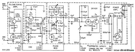
Novel phase modulator, based on bridged-T network, gives simple design dong with wide modulating capability. Transmitter has output of 300 mw at 108 Mc for telemetering data for up to 18 months from Van Allen radiation bell.-A. J. Fisher, W. R. Talbert, and W. R. Chittenden, Telemetry Transmitter for Radiation Satellite, Electronics, 33:19, p 68-69. (View)
View full Circuit Diagram | Comments | Reading(980)
LOW_ENERGY_PARTICLE_DETECTOR
Published:2009/7/19 22:16:00 Author:Jessie
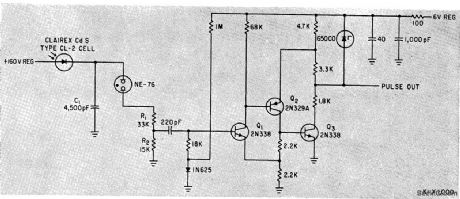
Change in conductivity of single-crystal photocell under irradiation is converted to pulse-code modulation by neon glow-tube relaxation oscillator whose Firing rate is determined by charging of C1 through photocell. Saturating bootstrap amplifier Q2 inverts and shapes pulses to drive accumulation register-J. W. Freeman, Energy Detector for Satellites, Electronics, 35:4, p 42-43. (View)
View full Circuit Diagram | Comments | Reading(1722)
0_TO__66V_AT_5mA
Published:2009/7/19 22:13:00 Author:Jessie
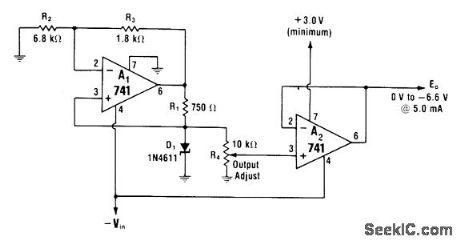
Voltage follower A2 buffers output that can be adjusted over full range from 0 V to zener limit with R4. Positive supply of A2 must go to voltage slightly more positive than +3 V common if linear output operation is required over full range.-W. G. Jung, IC Op-Amp Cookbook, Howard W. Sams, Indianapolis, IN, 1974, p 159-160. (View)
View full Circuit Diagram | Comments | Reading(606)
Differential_thermometer
Published:2009/7/19 22:13:00 Author:Jessie
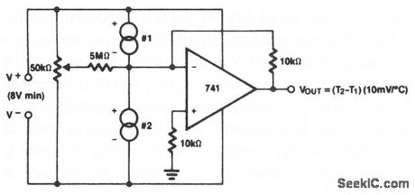
This circuit shows two AD590s and an op amp that is connected to measure temperature differential. The 50-kΩ potentiometer trims offsets in both devices, and can be used to set the size of the difference interval. The circuit can be used for liquid-level detection (if there is a measurable temperature difference in the liquid at different levels). Harris Semiconductors Data Acquisition) 1991 p. 12-9 (View)
View full Circuit Diagram | Comments | Reading(0)
Centigrade_thermometer
Published:2009/7/19 22:13:00 Author:Jessie
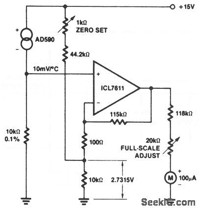
This circuit shows an AD590 and a low-current op amp that are connected to form a 0 to 100℃ thermometer. The readout is a 100-μA meter, which is adjusted by the Zero Set and Full-Scale Adjust potentiometer so that 1μA indicates 1℃, 10μA indicates 10℃, and so on. Harris Semiconductor Data Acquisition 1991 p 12-9 (View)
View full Circuit Diagram | Comments | Reading(1075)
7_23V_AT_12_2A
Published:2009/7/19 22:12:00 Author:Jessie
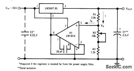
Ground terminal of LM340T-05 regulator is raised by amount equal to voltage applied to noninverting (+) input of opamp, to give output voltage set by R2 in resistive divider. Short-circuit protection and thermal shutdown are provided overfull output range.- Linear Applications, Vol. 2, National Semiconductor, Santa Clara, CA, 1976, AN-103, p6-7. (View)
View full Circuit Diagram | Comments | Reading(838)
LUNAR__PROBE__TRANSMITTER
Published:2009/7/19 22:10:00 Author:Jessie
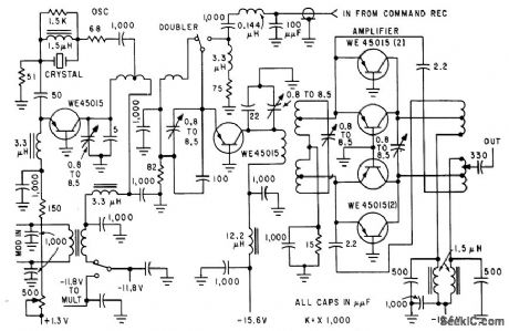
Five subcarrier channels are rsed in f-m/p-m systems to transmit ion density, two levels of micrometeorite particle impacts, magnetic field strength, and compartment temperature. Strength, and compartment temperature. Output stage uses four transistors in push-pull parallel to give 400mv output.-R. R. Bennett et al., Circuits for Space Probes, Electronics, 32:25, p 55-57. (View)
View full Circuit Diagram | Comments | Reading(731)
500000_PPS_SCALER
Published:2009/7/19 22:09:00 Author:Jessie
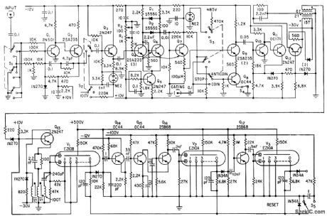
Uses seven fast gasfilled decade counter tubes driven by transistors, for counting pulses from nuclear radiation detector. Input channel, which can accept positive or negative pulses from 0.1 to100 v, has amplitude discriminator and coincidence-anticoincidence gating.-M. Birk, H. Brafman, and J. Sokolowski, Transistors Drive Half-Megacycle Cold-Cathode scaler, Electronics, 34:41, p 60-61. (View)
View full Circuit Diagram | Comments | Reading(907)
MALFUNCTION_MONITOR
Published:2009/7/19 22:09:00 Author:Jessie
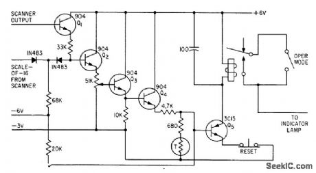
Used for monitoring missile in light while maintaining radio silence of telemetry transmitter unless abnormal condition is detected. After arming of missile, monitor can be used to transmit missile kill data.-R. C. Wright, Collecting Data from Live Missiles in Flight, Electronics, 34:12, p 46-49.
(View)
View full Circuit Diagram | Comments | Reading(681)
Microprocessor_controlled_TTY_to_A_D_convener_interface
Published:2009/7/19 22:09:00 Author:Jessie
Microprocessor-controlled TTY-to-A/D convener interface. The AD7570 is a 10-bit CMOS A/D convener (courtesy Analog Devices, Inc.). (View)
View full Circuit Diagram | Comments | Reading(1105)
Single_setpoint_temperature_controller
Published:2009/7/19 22:09:00 Author:Jessie
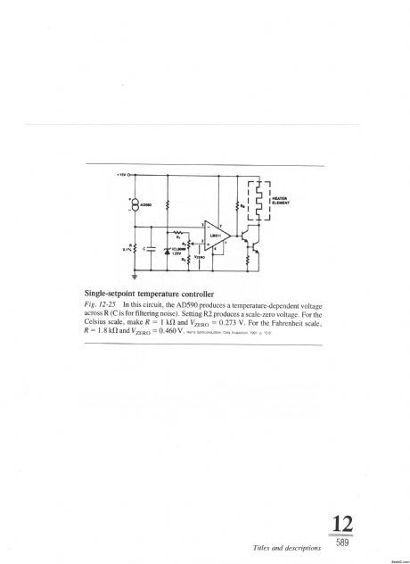
In this circuit, the AD590 produces a temperature-dependent voltage across R (C is for filtering noise). Setting R2 produces a scale-zero voltage. For the Celsius scale, make R=1 kΩ and VZERO=0.273 V. For the Fahrenheit scale, R=1.8kΩand VZERO=0.460V. Harris Semiconductors. Data Acquisition 1991 p 12-8 (View)
View full Circuit Diagram | Comments | Reading(670)
O_20V_HIGH_PRECISION
Published:2009/7/19 22:07:00 Author:Jessie
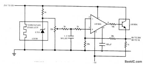
National LM199 temperature-stabilized 6.95-V reference feeds LM108A opamp that is buffered by LM195K power transistor IC which provides full overload protection.- Li near Applications, Val. 2, National Semiconductor, Santa Clara, AN-161,p6. (View)
View full Circuit Diagram | Comments | Reading(733)
NEUTRON_COUNTING_TRANSMITTER
Published:2009/7/19 22:07:00 Author:Jessie
Used with cosmic-ray neutron counter to drive con ventional radiosonde. Signals above preset amplitude trigger subcarrier gate that in turn frequency-modulates r-f carrier.-L. Hillman and R. C. Haymes, Modifying a Telemetry System for Balloon-Borne Neutron Detection, Electronics, 34:11, p 60-63.
(View)
View full Circuit Diagram | Comments | Reading(853)
BOOSTING_OUTPUT_CURRENT
Published:2009/7/19 22:06:00 Author:Jessie
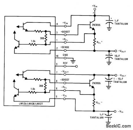
External NPN pass transistor is added to each section of LM125 precision dual tracking regulator to in-crease maximum output current by factor equal to beta of transistor. To prevent overheating and destruction of pass transistors and result, ant damage to regulator, series resistor RCL, is used to sense load current. When voltage drop across RCL equals current-limit sense voltage in range of about 0.3 to 0.8 V (related to junction temperature), regulator will current-limit. Maximum load current is about 1A for 25℃ junction and 0.6 ohm for RCL. LM125 provides ±15V, LM126 provides ±12V, and LM127 provides +5V and -12V.-T. Smathers and N. Sevastopoulos, LM125/LM126/LM127 Precision Dual Tracking Regulators, National Semiconductor, Santa Clara, CA, 1974, AN-82, p 5. (View)
View full Circuit Diagram | Comments | Reading(771)
Sample_and_hold_interface_with_an_AD571_10_bit_A_D_converter
Published:2009/7/19 22:06:00 Author:Jessie
Sample-and-hold interface with an AD571 10-bit A/D converter (courtesy Analog Devices, Inc.). (View)
View full Circuit Diagram | Comments | Reading(725)
±15V_TRACKING_1
Published:2009/7/19 22:04:00 Author:Jessie
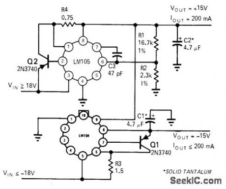
Arrangement uses LM104 negative regulator to track positive regulator, with both regulators adjusted simultaneously by changing R1. Inverting opamp can be added to provide negative output voltage while using positive voltage as reference.-R. C. Dobkin, One Adjustment Controls Many Regulators, EDN Magazine, Nov. 1, 1970, p 33-35. (View)
View full Circuit Diagram | Comments | Reading(855)
ARITHMETIC_BINARY
Published:2009/7/19 22:03:00 Author:Jessie
Uses 2N501 series-triggered transistors, catching diodes, and peaking coils operating at date input rate of about 15 Mc, in neutron time-of-flight and pulsed-neutron measurements.-E. J. Wade, Digital Instrumentation for Nuclear Research Tests, Electronics, 33:43, p 68-71.
(View)
View full Circuit Diagram | Comments | Reading(663)
| Pages:114/291 At 20101102103104105106107108109110111112113114115116117118119120Under 20 |
Circuit Categories
power supply circuit
Amplifier Circuit
Basic Circuit
LED and Light Circuit
Sensor Circuit
Signal Processing
Electrical Equipment Circuit
Control Circuit
Remote Control Circuit
A/D-D/A Converter Circuit
Audio Circuit
Measuring and Test Circuit
Communication Circuit
Computer-Related Circuit
555 Circuit
Automotive Circuit
Repairing Circuit