
power supply circuit
Index 116
Temperature__to_frequency_converter
Published:2009/7/19 22:27:00 Author:Jessie
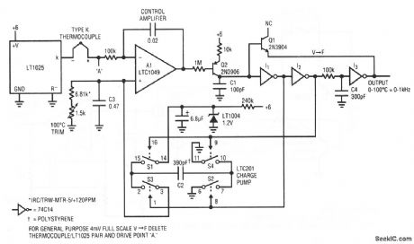
This circuit produces a 0- to 1-kHz output in response to a sensed 0 to 1 00℃ temperature range. Cold-junction compensation is included, and accuracy is within 1℃ with stable 0. 1℃ resolution. A single 4.75- to 10-V supply is required, with a maximum current consumption of 360μA. To calibrate this circuit, disconnect the thermocouple and drive point A with 4.06 mV. Then, set the 1.5-kΩ trim for exactly 1000-Hz output. Connect the thermocouple and the circuit is ready for use. Recalibration is not required if the thermocouple is replaced. Linear Technology Corporation 1991 AN45-8 (View)
View full Circuit Diagram | Comments | Reading(679)
DUAL_TRACKING
Published:2009/7/19 22:35:00 Author:Jessie


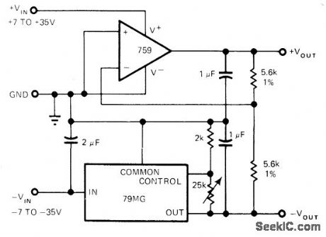
Uses one 759 power opamp for positive output, connected to track with 79MG negative voltage regulator having adjustable output. Common-mode range of 79MG includes ground, permitting operation from single supply. Circuit can also be built with two power opamps, one inverting and the other noninverting.-R. J. Apfel, Power Op Amps-Their Innovative Circuits and Packaging Provide Designers with More Options, EDN Magazine,Sept. 5, 1977, p 141-144. (View)
View full Circuit Diagram | Comments | Reading(1289)
8085A_CPU_to_8202_interface_with_no_read_or_write_wait_states
Published:2009/7/19 22:34:00 Author:Jessie

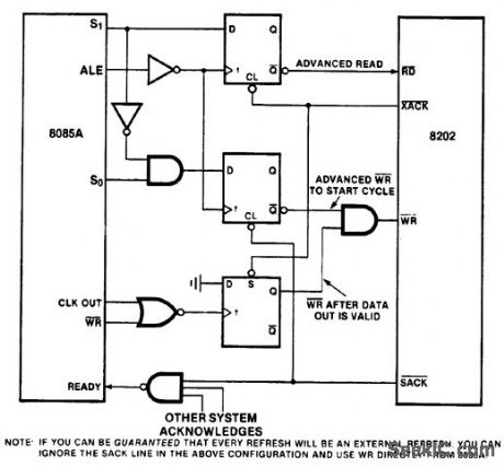
8085A CPU to 8202 interface with no read or write wait states (courtesy Intel Corporation). (View)
View full Circuit Diagram | Comments | Reading(906)
15_V_powered_radiation_detector
Published:2009/7/19 22:34:00 Author:Jessie
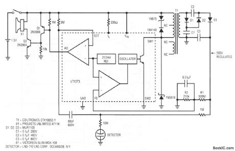
This circuit provides an audible tick signal each time radiation or a cosmic ray passes through the detector. The LT1073 switching regulator pulses T1 which, in turn, drives a voltage tripler to provide 500-V bias to the detector. R1 and R2 provide feedback to the LT1073, which closes the control loop. No calibration is needed. Linear Technology Corporation, 1991, AN45-11. (View)
View full Circuit Diagram | Comments | Reading(776)
±15V_TRACKING_AT_1A
Published:2009/7/19 22:33:00 Author:Jessie

Positive regulator tracks negative. IfQ1 and Q2 are perfectly matched, tracking action is unchanged over full operating temperature range, with tracking betterthan 100 mV. Regulationfrom no load to full load is 10 mV for positive side and 45 mV for negative side.- Linear Applications, Vol. 2, National Semiconductor, Santa Clara, CA, 1976, AN-103, p 8-9. (View)
View full Circuit Diagram | Comments | Reading(907)
Micropower_voltage_to_frequency_converter
Published:2009/7/19 22:32:00 Author:Jessie
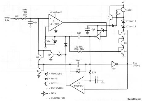
This circuit produces a 0- to 10-kHz output in response to a 0- to 5-V input, with a maximum current consumption of only 90μA. To calibrate, apply 50 mV and select the value at the C1 input for a 100-Hz output. Then, apply 5 V and trim the input potentiometer for a 10-kHz output. Linear Technology Corporation, 1991 AN45 15. (View)
View full Circuit Diagram | Comments | Reading(0)
F_M_TRANSMITTER
Published:2009/7/19 22:32:00 Author:Jessie
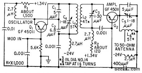
Provides 250 mw at 92 Mc, for use with balloon-borne ionizing radiation detectors. Variable-frequency oscillator can be used because only moderate stability is required.-D. Enemark, Transistors Improve Telemeter Transmitter, Electronics, 32:11, p 136-137. (View)
View full Circuit Diagram | Comments | Reading(794)
Scope_calibrator
Published:2009/7/19 23:18:00 Author:Jessie
This circuit uses an LM3909 to produce a precision square-wave signal that is used to calibrate scopes and scope probes or to check the gain and transient response of audio amplifiers (as described in chapter 1). The output is adjustable (with the 1-kΩ pot) and can be held to within a few tenths percent of 1 V.The output signal is a clean rectangular wave of about 1.5 ms On and 5.5 ms Off.The 0.01% temperature coefficient of the LM113 regulator results in negligible drift of the waveform amplitude under lab conditions. Because the circuit is battery powered, there is no inconvenient line cord, and no noise or hum. National Semiconductor. Linear Applications Handbook 1991 p 404 (View)
View full Circuit Diagram | Comments | Reading(0)
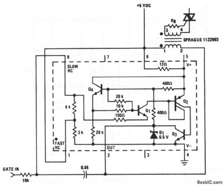
OVERVOLTAGE_CROWBAR
Published:2009/7/19 23:17:00 Author:Jessie
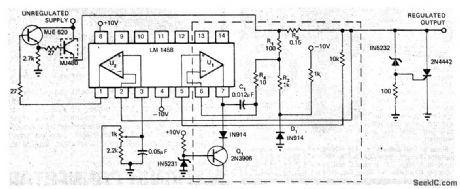
Components within dashed lines protect regulator IC from over current condition frequently encountered when zener-SCR crowbar is used across output.Regulated output is 5 V with IC shown. Article gives operating details of circuit and equation for shutdown time, which is about 1 s.-S. J. Pirkle, Circuit Protects Power Supply Regulator from Overcurrent, EDN Magazine, Feb. 5, 1973, p89. (View)
View full Circuit Diagram | Comments | Reading(845)
Triac_trigger
Published:2009/7/19 23:16:00 Author:Jessie
This circuit uses an LM3909 (operating from a standard 5-V logic supply) to trigger a triac (chapter 8). With no gate input, or a TTL-logic high input, the LM3909 is biased off because pin 1 is tied to V+. With a logic low at the gate input', the LM3909 provides 10-μs pulses at about a 7-kHz rate. A TTL gate loaded only by this circuit is assumed because worst-case voltage swing might be insufficient. The trigger is not of the synchronized zero-crossing type (chapter 8) because the first trigger pulse after gating on could occur at any time. However, the repetition rate is such that after the first cycle, a triac is triggered within 8 V of zero (with a resistive load and a 1 15-Vac line). National Semiconductor Linear Applications Handbook 1991 p. 403 (View)
View full Circuit Diagram | Comments | Reading(0)
SLOT_ANTENNAFIER
Published:2009/7/19 23:15:00 Author:Jessie
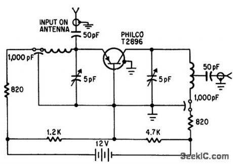
T-bar-fed 420-Mc slot antennafier for space vehicles has gain of 10 db, 100-Mc bandwidth, and 7.8 db noise figure.-J. F. Rippin, Making the Antenna on Active Partner, Electronics, 38:16, p 93-96. (View)
View full Circuit Diagram | Comments | Reading(633)
Series_shunt_chopper_for_low_input_voltages
Published:2009/7/19 23:10:00 Author:Jessie
Series-shunt chopper for low input voltages (courtesy Motorola Semiconductor Products Inc.). (View)
View full Circuit Diagram | Comments | Reading(707)
VOLTAGE_ADAPTER
Published:2009/7/19 23:15:00 Author:Jessie
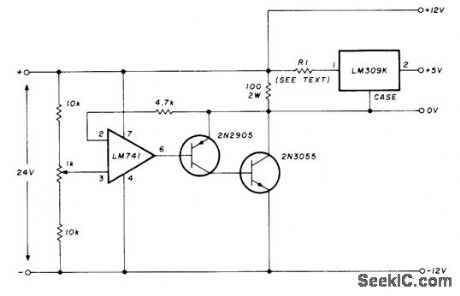
Bench power supply provides ±12 V and +5 V from single regulated 24-V source, for use with many ICs. Both t2-V supplies can be adjusted in same direction by varying 24-V source or in opposite directions by adjusting 1K pot. RI is used to decrease power dissipated in LM309K voltage regulator and is normally 2.2 ohms.-J. A. Plat, Voltage Adapter for MSI/LSI Circuits, Ham Radio, March 1978, p 115. (View)
View full Circuit Diagram | Comments | Reading(890)
Whooper_siren
Published:2009/7/19 23:14:00 Author:Jessie
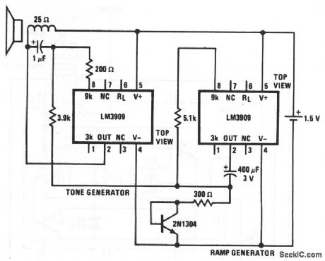
This circuit uses two LM3909s, one as a tone generator and one as a ramp generator, to produce a whooper sound that is somewhat like the electronic sirens that are used on city police cars, ambulances, and airport crash wagons. The rapid modulation makes the tone seem louder for the same amount of power input. The tone generator is similar to that of the Fig. 12-55 circuit, except that the pushbutton is replaced by a rapidly rising and falling modulating voltage that is produced by the ramp generator. National Semiconductor Linear Applications Handbook 1991, p 402, (View)
View full Circuit Diagram | Comments | Reading(833)
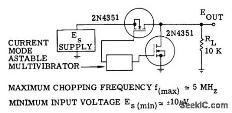
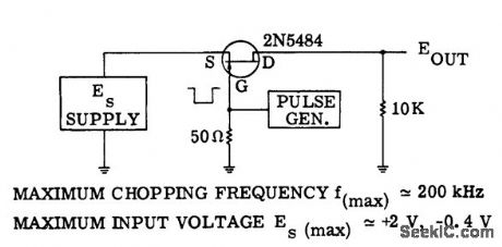
MOSFET_chopper_with_extended_range_of_±3_volts
Published:2009/7/19 23:13:00 Author:Jessie
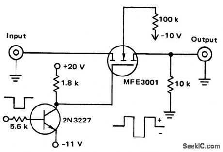
MOSFET chopper with extended range of ±3 volts (courtesy Motorola Semiconductor Products Inc.).
(View)
View full Circuit Diagram | Comments | Reading(1029)
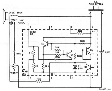
Fire_siren
Published:2009/7/19 23:13:00 Author:Jessie
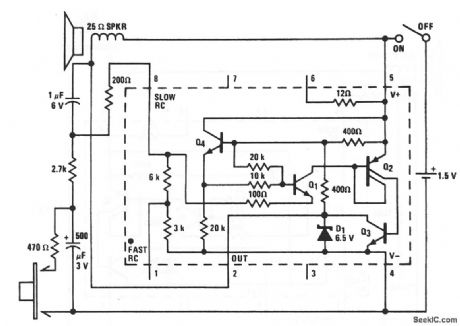
This LM3909 circuit produces a rapidly rising wail upon pressing the button, and a slower coasting down sound upon release. If it is desirable to have the tone stop sometime after the button is released, an 18-kΩ resistor can be placed between pins 8 and 6 of the LM3909. The sound is then much like that of a motor-driven siren, National Semiconductor Linear Applications Handbook, 1991 p. 402.
(View)
View full Circuit Diagram | Comments | Reading(2412)
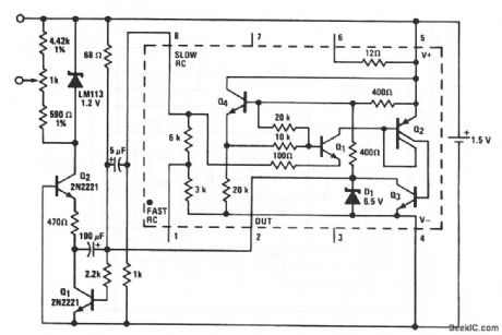
_5V_WITH_PROTECTION_
Published:2009/7/19 23:12:00 Author:Jessie
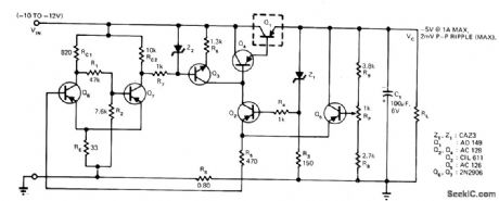
Switching- type short-circuit protection network uses R7 connected to Schmitt trigger Q6-Q7. Ground is provided by Q7 which is normally conducting. ff out-put of regulator is short-circuited, current through Q1 increases; at predetermined limit, a6 conducts and cuts off Q7 breaking ground connection of R7 and thus cutting off Q3 Power transistorQ1 is also cut of, and output current begins to decrease. When load current drops below another predetermined level, Q6 again goes off and Q7 turns on to begin another ON/OFF cycle, with switching process continuing until short-circuit is removed.-H. S, Raina and R. K. Misra, Novel Circuit Provides Short Circuit Protection, EDN Magazine, June 5, 1974, p 84. (View)
View full Circuit Diagram | Comments | Reading(1054)
Electronic_
Published:2009/7/19 23:11:00 Author:Jessie
With this circuit, the LM3909 oscillates at the speaker-cone free-air resonance point. That is, if the speaker is in an enclosure with a higher resonant frequency than the speaker, this becomes the frequency at which the circuit oscillates. An educational audio-demonstration device, or simply an enjoyable toy, has been fabricated as follows. A roughly cubical box of about 64 3 was made with one end able to slide in and out like a piston. The box was stiffened with thin layers of pressed wood, etc. Speakers, circuit, battery, and all were mounted on the sliding end, with the speaker facing out through a 21/4 hole. A tube was provided (21/2 long, 5/16 ID) to bleed air in and out as the piston was moved while not affecting resonant frequency. Minimum volume with the piston in was about 10 3. Slide tones can be generated, or a tune played, by properly positioning the piston part and working the push button. National Semiconductor Linear Applications Handbook 1911 p 401. (View)
View full Circuit Diagram | Comments | Reading(738)
Series_chopper_using_an_N_channel_JFET
Published:2009/7/19 23:10:00 Author:Jessie
Series chopper using an N-channel JFET (courtesy Motorola Semiconductor Products Inc.). (View)
View full Circuit Diagram | Comments | Reading(584)
1000V_AT_100W
Published:2009/7/19 23:10:00 Author:Jessie
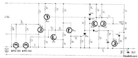
Two Delco DTS-723 transistors in series function as pass element of regulator in which differential amplifier Q1-Q2 senses output voltage and compares it with reference voltage at base of O2. Difference signal is amplified by Q3-Q4 for feed to Q5. 12-V regulated supply is referenced to high side of output voltage through R2. R1 is chosen so regulator shuts down when load current reaches 120 mA and triggers Schmitt trigger Q8-Q9 which fires SCR. When overload is removed, circuit returns to normal operation. Input voltage range of 1200-1500 V gives 0.1% regulation at full load.- 1000-Volt Linear DC Regulator, Delco, Kokomo, IN, 1974, Application Note 45. (View)
View full Circuit Diagram | Comments | Reading(886)
| Pages:116/291 At 20101102103104105106107108109110111112113114115116117118119120Under 20 |
Circuit Categories
power supply circuit
Amplifier Circuit
Basic Circuit
LED and Light Circuit
Sensor Circuit
Signal Processing
Electrical Equipment Circuit
Control Circuit
Remote Control Circuit
A/D-D/A Converter Circuit
Audio Circuit
Measuring and Test Circuit
Communication Circuit
Computer-Related Circuit
555 Circuit
Automotive Circuit
Repairing Circuit