
power supply circuit
Index 118
Remotely_powered_sensor_amp
Published:2009/7/19 22:41:00 Author:Jessie
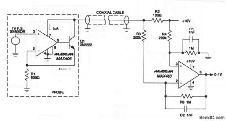
A simple two-wire current transmitter uses no power at the transmit-ting end (except that from the transmitted signal). At the transmitter, a 0- to 1-V input drives a MAX406 and npn transistor that is connected as a voltage-controlled current source. Although the MAX406 supply current is taken from the signal, only 1-μA out of 2-mA error is added. The output is sent through the coax to the MAX480, which reconstructs a ground-referenced 0- to 1-V signal. Maxim 1992, Applications and Product Highlights p. 5-9 (View)
View full Circuit Diagram | Comments | Reading(701)
SC_MP_to_cassette_tape_recorder_interface
Published:2009/7/19 22:40:00 Author:Jessie
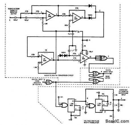
SC/MP to cassette tape recorder interface (courtesy National Semiconductor Corporation). (View)
View full Circuit Diagram | Comments | Reading(851)
Buffered_pH_probe_allows_low_cost_cable
Published:2009/7/19 22:40:00 Author:Jessie
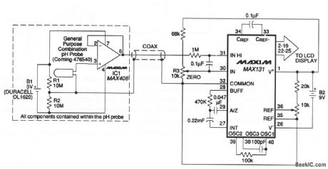
The probe circuit eliminates expensive low-leakage cables that often connect pH probes to meters. A MAX406 and a lithium battery are included in the probe housing. A conventional low-cost coax carries the buffered pH signal to the MAX131 A/D converter. The battery life depends on the dc loading of the amplifier output (MAX131 input current and cable leakage). In most cases, battery life exceeds the functional life of the probe. Maxim, 1992, Applications and Product Highlights p 5-9 (View)
View full Circuit Diagram | Comments | Reading(830)
Long_life_battery_powered_light_detector_alarm
Published:2009/7/19 22:38:00 Author:Jessie
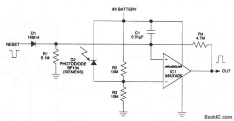
This circuit draws only 1.5μA. At this load, a 9-V alkaline battery can supply 200 mA/hours, which translates to a 15-year life (the shelf life of the battery will most likely end sooner). The circuit output latches high when light is detected. If the sensor is exposed, the output remains on until it is reset. The MAX406 operates as a comparator and as a latch by adding hysteresis externally via R4. Maxim 1992, Applications and Product Highlights, p 5-8 (View)
View full Circuit Diagram | Comments | Reading(959)
8085_CPU_to_RS_232C_interface_using_an_MC1488_and_an_MC1489
Published:2009/7/19 22:38:00 Author:Jessie

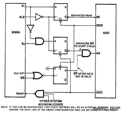
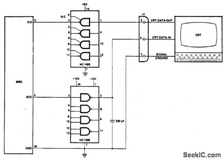
8085 CPU to RS-232C interface using an MC1488 and an MC1489 (courtesy Intel Corporation). (View)
View full Circuit Diagram | Comments | Reading(1854)
CURRENT_FOLDBACK_PROTECTION
Published:2009/7/19 22:37:00 Author:Jessie
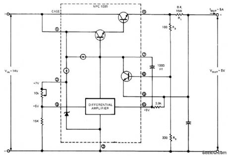
MPC1000 hybrid regulator provides regulated output of 5 V at 5 A from 14-V input. Values of components are based on foldback current of 6 A and short-circuit current of 2 A; this ensures that dissipation of regulator on short-circuit is Iess than dissipation at rated Ioad. Short-circuit current is controlled by diode drop across Ra and foldback current by drop across R2 Article gives design equations and procedure for obtaining other output voltages. Circuit also serves to limit starting surges into capacitive load, and reduces heatsink size and transistor ratings. ReturningR3 to pin 2 of MPC1000 instead of pin 3 gives lower short-circuit current, improves ef-ficiency, and reduces heat generation. Foldback protection is not suitable for variable-output supplies because foldback current is propor-tional to output voltage.-R. L. Haver, Use Cur-rent Foldback to Protect Your Voltage Regula-tor, EDNMagazine, Aug. 20, 1974, p 69-72. (View)
View full Circuit Diagram | Comments | Reading(1381)
Bipolar_voltage_to_frequency_converter
Published:2009/7/19 22:36:00 Author:Jessie
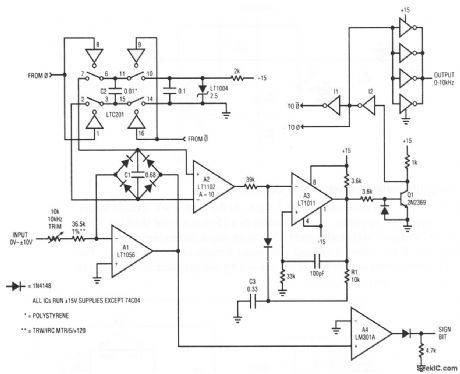
This circuit produces a 0- to 10-kHz output in response to a 0- to ± 10-V input. The A4 output indicates the sign (+ or -) of the input. To calibrate, apply either a - 10- or + 10-V input and set the 10-kΩ trim for exactly a 10-kHz output. The low offsets of A1 and A2 permit operation down to a few Hz with no zero trim required. Linear Technology Corporation 1991 AN45-17 (View)
View full Circuit Diagram | Comments | Reading(707)
FOUR_TRACE_OSCILLOSCOPE_ADAPTER
Published:2009/7/10 1:59:00 Author:May
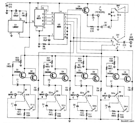
This simple adapter uses an oscillator (567) to drive a counter (U2) and switch (U3) that selects the output of one of four scope preamps (Q1/Q2 through Q7/Q8) and feeds it to buffer Q9 and output jack J1. J2 provides synch to the scope. R20 through R23 are posting controls for channels A through D (J3 through J6). SlA-B through S4A-B are switched attenuators, one for each channel. Switching rate is about 125 kHz. This circuit is useful for adding four-trace operation to inexpensive oscilloscopes. Signal levels of 0 to 20 V can be handled. (View)
View full Circuit Diagram | Comments | Reading(945)
BIPOLAR_REFERENCE_SOURCE
Published:2009/7/9 23:34:00 Author:May
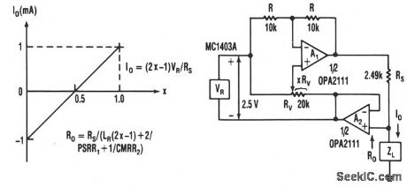
This current source has continuous control of the magnitude and polarity of its amplifier gain and needs only one voltage reference. The circuit includes reference VR, voltage-amplifier circuit A1 with gain-setting resistor RS, and bootstrap-follower amplifier A2. The bootstrapping converts the circuit to a current source and allows the load to be grounded. Any voltage developed across load ZL feeds back to the reference and voltage amplifier, making their functions immune to that voltage. Then the current-source circuitry floats, instead of the load.The voltage reference is connected to both the inverting and noninverting inputs of A1 ; this provides a balanced combination of positive and negative gain. The inverting connection has equal feedback resistors, R, for a gain of -1, and the noninverting connection varies according to the fractional setting, X, of potentiometer RV .X is controls the noninverting gain and adjusting it counters the effect of some of the inverting gain. The value of X is the portion of RV's resistance from the noninverting input of A1 to the temporarily grounded output of A2. Between potentiometer extremes, the current varies with X ± 1 mA. (View)
View full Circuit Diagram | Comments | Reading(993)
MIDDLEBROOCK_SERIES_STABILIZED_SUPPLY
Published:2009/7/20 2:35:00 Author:Jessie
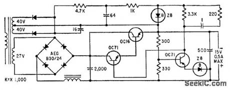
Provides constant 15 v for moderately variable load, with temperature coefficient of 1 my per degree C, 4 my peak-to-peak ripple, and 0.5 amp maximum current.-E. Baldinger and W. Czaja, Designing Highly Stable Transistor Power Supplies, Electronics, 32:39, p 70-73. (View)
View full Circuit Diagram | Comments | Reading(659)
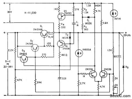
SERIES_RUGULATOR_WITH_TRANSISTOR_PREREGULATOR
Published:2009/7/20 2:31:00 Author:Jessie
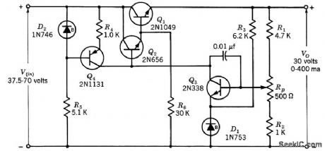
Design procedure is give to meet specification that regulation factor F range from 0.001 for no load to 0.00145 for full load when input voltage varies over range specified. Output varies from 30.7 v to 31.l over temperature range of -50 to +125℃.-Texas Instruments Inc., Transistor Circuit Design, McGraw-Hill, N.Y., 1963, p 160. (View)
View full Circuit Diagram | Comments | Reading(784)
TRANSDUCTORS_STABILIZE_HIGH_POWER_RECTIFIER
Published:2009/7/20 2:27:00 Author:Jessie
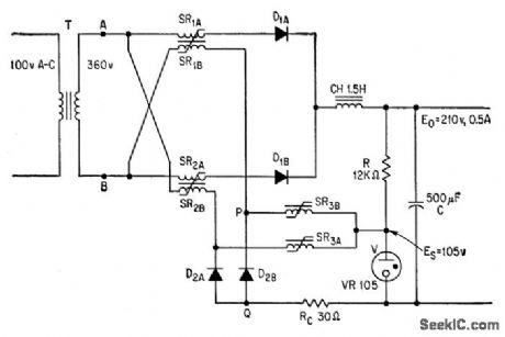
Rectangular-loop saturable reactors SR in single-phase power supply hold output voltage constant within l% at load currents of 0 to 20 amp and line voltage variations of 50%. Choice of components de-determines power capacity.-T. Kurimura and K. Yamamura, New Way to Use Saturable Reactors: Stabilizing High-Power Rectifiers, Electronics, 36:21, p 61-66. (View)
View full Circuit Diagram | Comments | Reading(599)
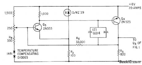
SHORT_CIRCUIT_PROTECTION
Published:2009/7/20 2:25:00 Author:Jessie
Series regulator has automatic pulsing-type short-circuit protection. D1, R2, and R3 form constant. current prelimiting circuit, and Q4 is shut-off transistor. Unijuunction transistor Q5 pulses continuously. D2 completes discharge path of C1 through R4 when Q5 fires.-A. G. Lloyd, Overload Protection for Transistor Voltage Regulators, Electronics, 33:52, p 56-59. (View)
View full Circuit Diagram | Comments | Reading(2154)
REGULATOR_DIODE_STRING
Published:2009/7/20 2:21:00 Author:Jessie
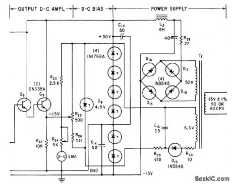
Six 5% silicon regulator diodes operated at 65 ma give +30 v at 90 ma and -15 v of 95 ma. Used with vibration-measuring circuit whose peak reading output drives d-c amplifier Q8-Q9 to give required output current of 2 ma for d-c meter or recorder.-H. A Harriman and W. M. Trenholm, Vibration Measurements with Peak. Reading Circuit, Electronics, 35:20, p 57-59. (View)
View full Circuit Diagram | Comments | Reading(700)
14_V_TWO_ZENER_REGULATOR
Published:2009/7/20 2:20:00 Author:Jessie
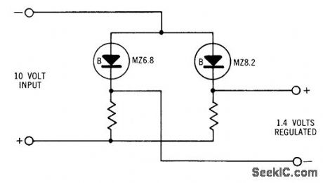
Used to deliver regulated voltage lower thon is normally available with zener diodes. Difference voltage is used for output. Gives excellent temperature compensation because both diodes tend to drift in same direction.- Zener Diode Handbook, International Rectifier Corp., 1960, p 54. (View)
View full Circuit Diagram | Comments | Reading(1022)
VARIABLE_FREQUENCY_A_C_REGULATOR
Published:2009/7/20 2:17:00 Author:Jessie
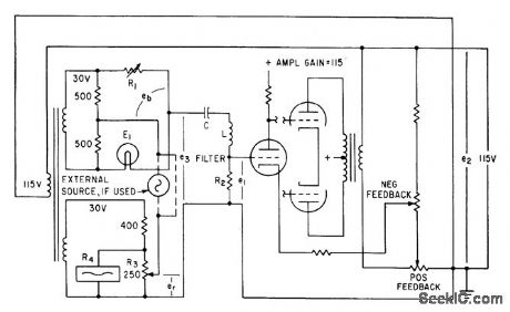
Commercial ballast tube in thermal regulating bridge is used with feedback-stabilized amp lifer and liter to regulate ac voltage source to 0.1%. Used for instrument calibration. Triode oscillator circuit oscillates al series resonant frequency of LC filter, which can be-tuned from 50 to 2,000 cps.-E. A Gilbert, Precision Variable Frequency Power Supply, Electronics, 34:2, p 99-100. (View)
View full Circuit Diagram | Comments | Reading(807)
High_gain_107_MHz_FM_limiter_amplifier_detector_for_FM_receivers
Published:2009/7/20 2:16:00 Author:Jessie
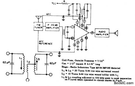
High-gain 10.7 MHz FM limiter/amplifier/detector for FM receivers. Supply voltage should be 30 volts with resistor R being 750 ohms. See lower diagram for specific discriminator information. The bypass capacitor at pin 5 is 0.001,μF.Bypass capacitors at pins 2, 9, 11, and 12 are 0.05μF. The input transformer is a standard 10.7 MHz IF type (courtesy GTE Sylvania Incorporated). (View)
View full Circuit Diagram | Comments | Reading(963)
TWO_LEVEL_REGULATION_FOR_12_V_AT_02A
Published:2009/7/20 2:15:00 Author:Jessie
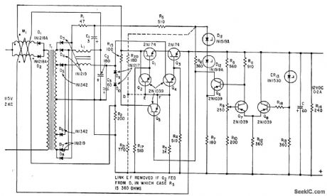
Transformer provides two voltages, one for normal operation and the other to supply current during transients. Storage capacitance is only one-tenth of that needed with conventional series regulator.-F. L. Ward, Novel Bi-Level Regulator Reduces Storage Capacitance, Electronics, 35:32, p 74-75. (View)
View full Circuit Diagram | Comments | Reading(678)
VOLTAGE_STABILIZER_USING_FOUR_CONSTANT_CURRENT_DIODES
Published:2009/7/20 2:12:00 Author:Jessie
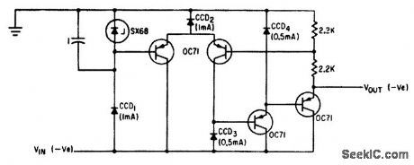
Value of stabilized output voltage can be adjusted by placing potentiometer in parallel with SX68 zener diode and connecting base of Q1 to slider. With this arrangement, magnitude and phase angle of output voltage setting.-T. K. Hemingway, Applications of the Constant-Current Diode, Electronics, 34:42, p 60-63. (View)
View full Circuit Diagram | Comments | Reading(997)
ZENER_REFERENCE
Published:2009/7/20 2:36:00 Author:Jessie
Sensing circuit for 6-v constant-voltage transformer -regulated power supply develops error signal for controlling shunt transistors.-J. T. Keefe, Transformer and Shunt Transistors Regulate D-C Power Supply, Electronics, 34:20, p 99:101. (View)
View full Circuit Diagram | Comments | Reading(607)
| Pages:118/291 At 20101102103104105106107108109110111112113114115116117118119120Under 20 |
Circuit Categories
power supply circuit
Amplifier Circuit
Basic Circuit
LED and Light Circuit
Sensor Circuit
Signal Processing
Electrical Equipment Circuit
Control Circuit
Remote Control Circuit
A/D-D/A Converter Circuit
Audio Circuit
Measuring and Test Circuit
Communication Circuit
Computer-Related Circuit
555 Circuit
Automotive Circuit
Repairing Circuit