
power supply circuit
Index 103
MONO_WITH_NEGATIVE_RECOVERY_TIME
Published:2009/7/17 4:04:00 Author:Jessie
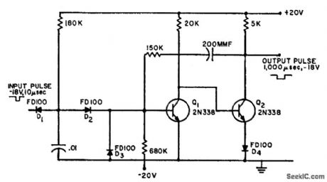
Will respond to input pulses occurring even before end of output pulse, which in effect gives negative recovery time. If circuit begins normal 1,000-microsec cycle and another trigger pulse arrives in 500 microsec, output pulse will last 1,500 microsec, or 500 microsec longer than usual. In other words, output pulse continues for 100 microsec after last trigger pulse. Input pulses should be of standardized voltage and long enough to discharge 0.01-mfd capacitor.-Monostable Circuit with Negative Recovery Time, Electronic Circuit Design Handbook, Mactier Pub. Corp., N.Y., 1965, p 72. (View)
View full Circuit Diagram | Comments | Reading(751)
WATERING_CONTROL_WITH_RF_MOISTURE_SENSING
Published:2009/7/17 4:03:00 Author:Jessie
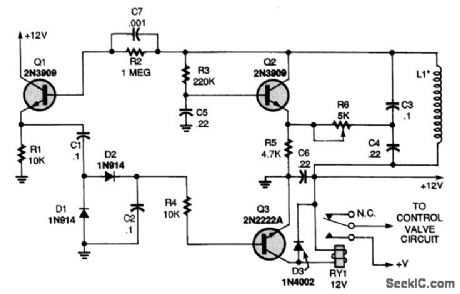

The moisture sensor does not depend on the ohmic resistance of the soil to activate the water valve. Instead, a VLF oscillator circuit with its tuned inductor buried In the soil senses the moisture content by absorption,Transistor Q2,L1,C3,and 04,make up a simple Hartley oscillator The circuit oscillates at about 16 kHz Transistor Q1,in an emitter-follower configuration,isolates the output circuit from loading or influencing the oscillator circuit Diodes D1 and D2 convert the RE Signal to dc to supply bias current for Q3,which operates the water-valve relay as long as the oscillator's output signal is sufficient to turn it on The oscillator,s sensitivity to varying soil conditions is set by R6,a 10-turn trimmer potentiometer The inductor,L1,consists of a 100-ft length of #26 plastic-covered wire wound in a 4-inch loop and kept together with electrical tape The loop is one area where much can be gained by experimenting,A pancake loop might be more sensitive or a different-shaped loop might work better,Also try different oscillator frequencies. (View)
View full Circuit Diagram | Comments | Reading(975)
RECORD_PLAYBACK_CIRCUIT_WITH_AUTOMATIC_POWER_DOWN
Published:2009/7/17 4:03:00 Author:Jessie
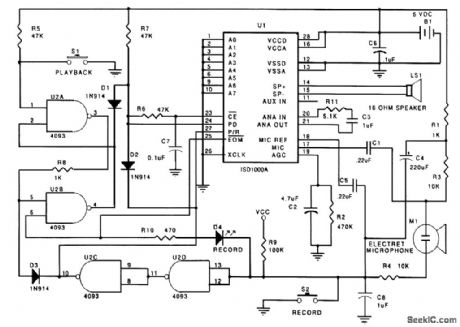
Many applications for sound recording and reproduction, where battery power is necessary, require minimum power consumption. A circuit that achieves automatic power down in a record-and-play application is shown. The cross-coupled latch, consisting of a 4093 Schmitt trigger quad two-input NAND package (U2A and U2B), works to control the PD and CB pins for the Play mode. Circuitry for the Record mode consists of U2C and U2D plus several support components. To start the Record cycle, S2 supplies the ground to the microphone circuit and takes the input to U2D low. The Schmitt Trigger action of U2 debounces the logic input to the ISD1020A. (View)
View full Circuit Diagram | Comments | Reading(1131)
TGS_gas_smoke_detector_using_a_McMOS_gated_oscillator_for_triac_control
Published:2009/7/17 3:58:00 Author:Jessie

TGS gas/smoke detector using a McMOS gated oscillator for triac control (courtesy Motorola Semiconductor Products Inc.). (View)
View full Circuit Diagram | Comments | Reading(746)
Logarithmic_current_source
Published:2009/7/17 3:57:00 Author:Jessie
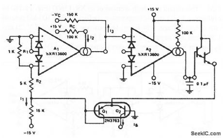
This circuit uses both sections of an XR-13600 (Fig. 11-1B) to form a logarithmic current source. The current can be used for IB (the bias current) in many OTA applications by providing a logarithmic current output for a linear voltage in.For example, the circuit can be used to bias the stereo volume control (Fig. 11-2) to provide temperature-independent stereo attenuation characteristics. EXAP Corporation Databook 1990 p5- 258 (View)
View full Circuit Diagram | Comments | Reading(1193)
_5_V_AT_4A_12_V_AT_025_AAND__24_V_AT_2_A
Published:2009/7/17 3:57:00 Author:Jessie
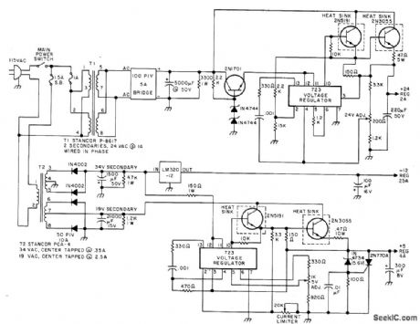
Provides regulated voltages needed for Sykes 7158 floppy disk and its interface controller, used in Southwest Technical Products MP-68 computer system. Circuit provides adjustable current limiting and overvoltage protection on 5-V supply. Output voltage adjustments are provided for 5-V and 24-V supplies. - P. Hughes, Interfacing the Sykes OEM Floppy Disk Kit to a Personal Computer, BYTE, March 1978, p 178-185. (View)
View full Circuit Diagram | Comments | Reading(1608)
MOISTURE_DETECTOR
Published:2009/7/17 3:56:00 Author:Jessie
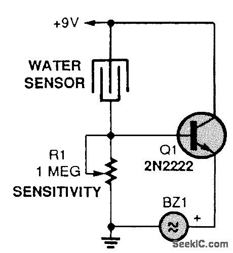
This simple circuit can save your house from water inundation. Also, it can save your electrical equipment from water damage. When raindrops fall on the water sensor, a small current flows, turning on Q1 and the buzzer. Alternatively, you could replace the buzzer with a relay to drive a pump. The water sensor can be made from an etched circuit board. (View)
View full Circuit Diagram | Comments | Reading(7180)
WATER_DETECTOR
Published:2009/7/17 3:54:00 Author:Jessie

The heart of the circuit is the LM1830 fluid detector. It contains all the circuitry needed to sense fluid levels and activate an external device (relay, etc). The IC generates an ac signal that is passed through two probes in the fluid. The IC's detector circuit senses the presence or absence of fluid by comparing the resistance between the probes with its internal reference resistance. When the probes detect the presence of water, the LM1830 will trigger Q1, and that in turn will trigger IC2 (an LM555), which starts a timing period. The output from pin 3 of IC2 closes the relay, and the bilge pump is activated for the duration of the timing period. The timing period is adjustable using R6, a 1-MΩ potentiometer. For the values shown, and depending on the setting of R6, the timing period is about 5 to 120 s. Components R4, D1, and C7 are tied to pin 4 of IC2 to hold the timer at RESET when power is first applied. (View)
View full Circuit Diagram | Comments | Reading(3153)
High_performance_high_noise_rejection_two_wire_data_transmission_system
Published:2009/7/17 3:54:00 Author:Jessie
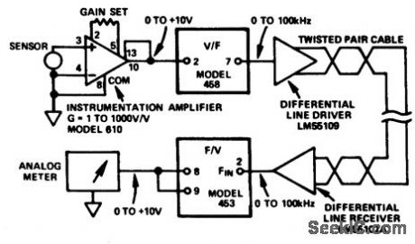
High-performance high-noise-rejection two-wire data transmission system. Instrumentation amplifier 610 amplifies the low-level transducer signal to apply to the 458 V/F converter. A differential line driver is used to drive the twisted pair. A differential line receiver is used to drive the 453 F/V converter, which in turn powers the analog meter (courtesy Analog Devices, Inc.). (View)
View full Circuit Diagram | Comments | Reading(660)
Voltage_reference_with_variable_TC
Published:2009/7/17 3:53:00 Author:Jessie
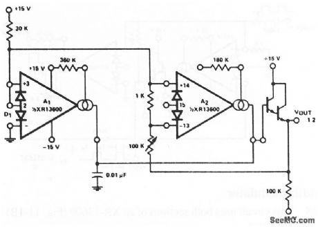
This circuit uses both sections of an XR-13600 (Fig. 11-1B) to form a voltage reference with variable temperature coefficient. The 100-kΩ potentiometer adjusts the output voltage, which has: 1) a positive TC above 1.2 V, 2) zero TC at about 1.2 V, and 3) a negative TC below 1.2V. This is done by balancing the TC of the A2 transfer function against the complementary TC of D1. EXRA Corporation Databook 1990,p 5-257 (View)
View full Circuit Diagram | Comments | Reading(727)
High_noise_immunity_data_transmission_system_using_a_V_F_converter
Published:2009/7/17 3:52:00 Author:Jessie
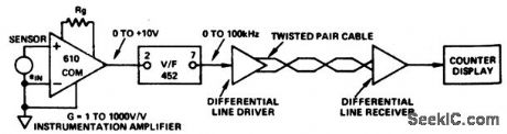
High-noise immunity data transmission system using a V/F converter. Model 610, an instrumentation amplifier, amplifies the low-level differential transducer signal up to the 10-voltfull scale input level of the452V/F convener. A differential line driver is used to drive a twisted pair. A differential line receiver is used to drive the digital counter and display (courtesy Analog Devices, Inc.). (View)
View full Circuit Diagram | Comments | Reading(636)
5_V_AT_3_A
Published:2009/7/17 3:52:00 Author:Jessie
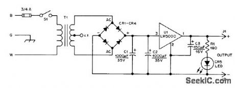
National LM5000 voltage regulator having built-in overload protection is basis of small bench supply for TTL work. Filament transformer rated 12.6 V at 3 A feeds full-wave bridge rectifier rated 200 PIV at 6 A, such as Radio Shack 276-1172. U1 requires heatsink insulated from chassis. Output filter C3 should be mounted directly on regulator terminals to minimize circuit oscillation. Output should read within 100 mV of 5 V. Radio Shack 276-047 LED serves as output indicator. Use 0.22-μF bypass between pins 2 and 3 of U1.-K. Powell, The 5 x 3 Power Supply, QST, May 1977, p 25-26. (View)
View full Circuit Diagram | Comments | Reading(648)
3_wire_plus_digital_ground_data_transfer_system_
Published:2009/7/17 3:52:00 Author:Jessie
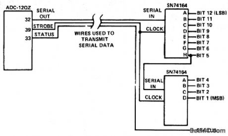
3-wire plus digital ground data transfer system (courtesy Analog Devices, Inc.). (View)
View full Circuit Diagram | Comments | Reading(667)
Two_wire_differential_data_transmission_system_using_an_MC75110_driver_and_an_MC75107_receiver
Published:2009/7/17 3:51:00 Author:Jessie
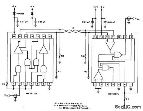
Two-wire differential data transmission system using an MC75110 driver and an MC75107 receiver (courtesy Motorola Semiconductor Products Inc.). (View)
View full Circuit Diagram | Comments | Reading(662)
13_V_AT_2_A_WITH_PNP_TRANSISTORS
Published:2009/7/17 3:50:00 Author:Jessie
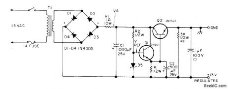
Reference voltage source q1 is 2N301, while series-pass regulator Q2 is 2N1523 D5 is 1N5245 15-V zener Secondary of T1 is 16-19 V, or can be 6-V and 12-V filament transformers in series. Article tells how to adapt circuit for other output voltages. - R. B. Joerger, Power Supply, 73 Magazine, Holiday issue 1976, p 40-41. (View)
View full Circuit Diagram | Comments | Reading(1220)
Dual_Schmitt_trigger_used_as_a_2_wire_differential_line_receiver_
Published:2009/7/17 3:50:00 Author:Jessie
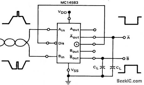
Dual Schmitt trigger used as a 2-wire differential line receiver (courtesy Motorola Semiconductor Products Inc.). (View)
View full Circuit Diagram | Comments | Reading(910)
60_hertz_nicad_battery_charger_with_voltage_sensing
Published:2009/7/17 3:49:00 Author:Jessie
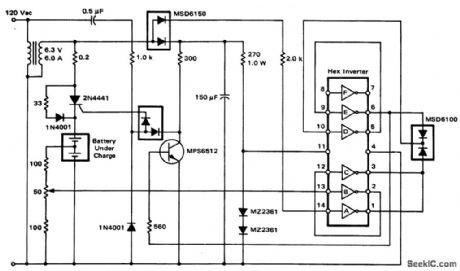
60-hertz nicad battery charger with voltage sensing. Hex inverter is an MC789P (courtesy Motorola Semiconductor Products Inc.). (View)
View full Circuit Diagram | Comments | Reading(1039)
20_kHz_nicad_battery_charger_with_voltage_sensing
Published:2009/7/17 3:47:00 Author:Jessie
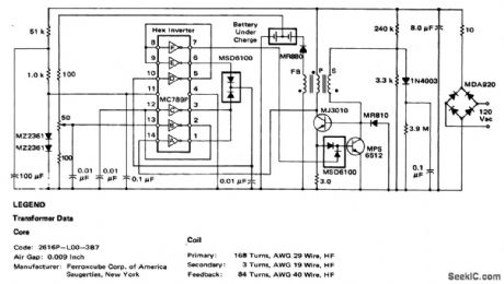
20 kHz nicad battery charger with voltage sensing (courtesy Motorola Semiconductor Products Inc.). (View)
View full Circuit Diagram | Comments | Reading(757)
12_volt_battery_charger_with_an_SOB_and_a_PUT_
Published:2009/7/17 3:44:00 Author:Jessie
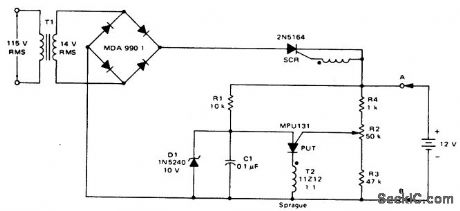
12-volt battery charger with an SOB and a PUT (courtesy Motorola Semiconductor Products Inc.). (View)
View full Circuit Diagram | Comments | Reading(1173)
ONE_CHIP_FRONT_END_AM_RECEIVER
Published:2009/7/17 3:43:00 Author:Jessie
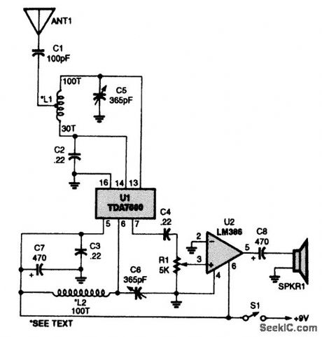
The schematic diagram of the receiver circuit is shown. About all you have to do is wind two coils, connect a few components together, and tie the input to a simple wire antenna, and a receiver is born. The two coils, L1 and L2, each comprised 100 turns of #28 enamel-covered copper magnet wire wound on T80-2 toroid cores (with a tap at the 30th turn on L1). (View)
View full Circuit Diagram | Comments | Reading(2193)
| Pages:103/291 At 20101102103104105106107108109110111112113114115116117118119120Under 20 |
Circuit Categories
power supply circuit
Amplifier Circuit
Basic Circuit
LED and Light Circuit
Sensor Circuit
Signal Processing
Electrical Equipment Circuit
Control Circuit
Remote Control Circuit
A/D-D/A Converter Circuit
Audio Circuit
Measuring and Test Circuit
Communication Circuit
Computer-Related Circuit
555 Circuit
Automotive Circuit
Repairing Circuit