
power supply circuit
Index 107
PRF_GENERATOR
Published:2009/7/19 20:32:00 Author:Jessie

Blocking oscillator operates in range of 200 to 2,000 pps, as radar repetition-rate generator having frequency stability of about 5%.-NBS, Handbook Preferred Circuits Navy Aeronautical Electronic Equipment, Vol. 1 Electron Tube Circuits, 1963, p NS-2. (View)
View full Circuit Diagram | Comments | Reading(0)
±15_V_AND_5_V_CAR_BATTERY_SUPPLY
Published:2009/7/10 20:52:00 Author:May

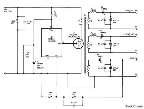
IC1is a switching regulator that generates a 45-kHz signal that drives the gate of MOSFET Q1.D1,D2, and D3 are Schottky diodes. The 5-V output is sensed as a reference; feedback to the chip turns offthe gate signal to Q1 if the voltage nses above 5 V.
T1 has Trifilar windings that assume about 2% regulation fr a 10-to 100-mA load change on the±15-V supplies, R1/D4 provide overvoltage protecti. T1 has a pnmary inductance ofabout 21 μH. Coreslze should allow 4-A peak currents. The turn ratios are 11 1/2 turns each for the 15-V supplies. 11 1/2 turns for the pnmary, and four turns for the 5-V secondary. The efficiency is about 75%. (View)
View full Circuit Diagram | Comments | Reading(1102)
CONSTANT_Q_FROM_1_CPS_TO_10_KC
Published:2009/7/17 9:47:00 Author:Jessie
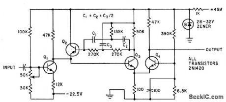
Symmetrical parallel-T R-C rejection filter in negative feedback loop of amplifier gives Q of 28 over frequency range, for frequency dependent noise measurements. Gain is about 5, and maximum output is about 5 V rms. –R. E. Hobson and L. Colcagno, Narrow Pass-Band Amplifier with Parallel-T Network, Electronics, 34:33, p 68. (View)
View full Circuit Diagram | Comments | Reading(677)
SQUELCH_ACTUATED_MOBILE_REPEATER
Published:2009/7/17 9:45:00 Author:Jessie
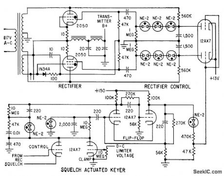
Thyratrons serve as rectifiers in transmitter power supply to avoid repeater malfunctions caused by relays. When incoming signal opens receiver squelch, thyratrons conduct and provide d-c power for transmitter. Under standby conditions, flip-flop keeps thyratrons nonconducting. When relaxation oscillator is activated by squelch tube voltages, flip-flop reverses and applies pulses to thyratrons to make them conduct. This prevents transmitter from being activated by receiver failure.-L. G. Sands, Design Trends in Mobile Radio Repeaters, Electronics, 32:47, p 82-84. (View)
View full Circuit Diagram | Comments | Reading(1307)
1000_MC_TO_200_MC_CONVERTER
Published:2009/7/17 9:24:00 Author:Jessie
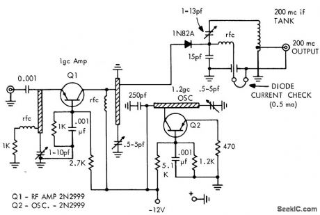
Used in measuring transistor noise figure at 1,000 Mc. Oscillator of converter operates at 1,200 Mc. Converter has gain of 10 db and 5 db noise figure.-Texas Instruments Inc., Solid-State Communications, McGraw-Hill, N.Y., 1966, p 349. (View)
View full Circuit Diagram | Comments | Reading(717)
200_MC_TRANSISTOR_NOISE_FIGURE_MEASUREMENT
Published:2009/7/17 9:19:00 Author:Jessie
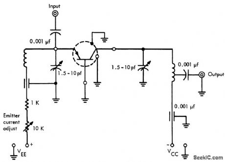
Input is fed by Hewlett-Packard 343A noise source, Output goes to 342A noise figure meter through 3-stage transistor post-amplifier. Input and output of test jig are tunable for best noise figure.-Texas Instruments Inc., Solid-State Communications, McGraw-Hill, N. Y., 1966, p 344. (View)
View full Circuit Diagram | Comments | Reading(810)
TRIODE_VARIABLE_RESISTANCE_THRESHOLD_CONTROL_SWITCH
Published:2009/7/17 9:17:00 Author:Jessie
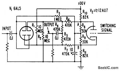
Passes only signals above predetermined positive and negative threshold value, for suppression of audio bockground noise. When V2 is cut off, threshold is at highest value, corresponding to off position of switch. With V2 conducting, threshold will be low and practically all signals appear unclipped at output, corresponding to on position of switch. Provides stable, nontransient switching, independent of changes in tube characteristics.-W. E. Earle, A-C Threshold Converts to Switch, Electronics, 31:1, p 96-99. (View)
View full Circuit Diagram | Comments | Reading(741)
12_14_V_AT_3_A
Published:2009/7/17 5:43:00 Author:Jessie
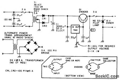
Basic circuit for operating mobile equipment off AC line uses IC voltage regulator in conjunction with series-pass transistor.-Circuits, 73 Magazine, Holiday issue 1976, p 170.
(View)
View full Circuit Diagram | Comments | Reading(2133)
5_V_WITH_DOUBLER
Published:2009/7/17 5:42:00 Author:Jessie
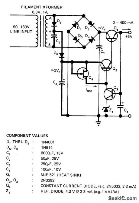
Doubling permits use of inexpensive 6.3-V filament transformer without risking loss of regulation when line voltage drops below about 105 V. With values shown, output varied only 6 mV for line voltage range of 95 to 135 V. Doubler circuit consists of C2, C3, D1, D3, D5, and D6.-A. Paterson, Voltage Doubler Prevents Supply from Losing Regulation, EDN Magazine, Nov. 1, 1972, p 46. (View)
View full Circuit Diagram | Comments | Reading(899)
_138_VDC_AT_18_A
Published:2009/7/17 5:36:00 Author:Jessie
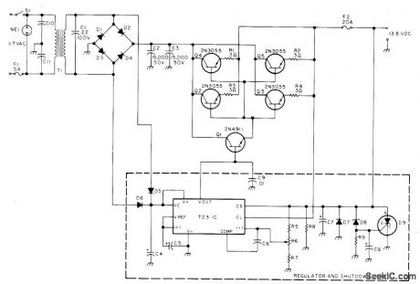
Developed for use with amateur radio transceiver. Transformer secondary is rated 25 VAC at 12 A. When output voltage exceeds 15 VDC, zener D8 (1N965A or equivalent) conducts and fires 2N4441 SCR to crowbar supply and protect transceiver Parts values are: R5 1.8 K, R6 2.5 K, R7 2.7 K, R8 1.5 K, R9 1 K, C4 250 Μf, C5-C6 1.2 μF, C7 220 μF, C8 100 μF, C9-C11 0.01 Pf, D1-D4 1N3492 or equivalent with 100 PIY at 18 A, D5-D6 1N4607 or equivalent, and D7 1N4002 or equivalent.-T. Lawrence, Build a Brute Power Supply, 73 Magazine, Aug. 1977, p 78-79. (View)
View full Circuit Diagram | Comments | Reading(2431)
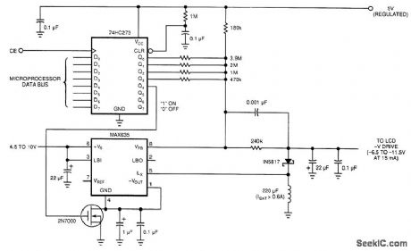
5_V_FROM_AC_OR_DC
Published:2009/7/17 5:33:00 Author:Jessie
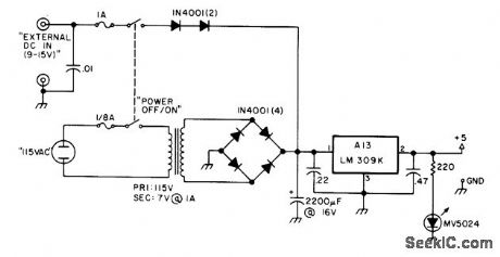
Developed for use with secondary frequency standard to permit checking frequency of amateur radio transmitter at station or in field. Any battery capable of delivering 250 mA at 9-15 V is suitable.-T. Shankland, Build a Super Standard, 73 Magazine, Oct. 1976, p 66-69. (View)
View full Circuit Diagram | Comments | Reading(764)
12_V_AT_5A
Published:2009/7/17 5:32:00 Author:Jessie
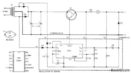
Uses MJ3000 Darlington power device as pass element providing gain of 1000 at 5 A. Output is set to current-limit at 6.5 A. Fuse at X is desirable. Values: R1 is 1.8 K; R2 is 2.5K trimpot; R3 is 2.7K; R4 is 1.5K; R5 is 0.1 ohm at 5 W; C1-C5 are 4000 μF each at 20 V; C6 is 250 μF at 25 V; C7-C8 are1.2 μF at 35 V; C9 is 220 pF; Dl-D2 are MR1120 or equivalent rated 6 A; D3-D4 are 1N4607 or equivalent; D5 is 1N4002 or equivalent; and T1 is 24-28 V CT secondary at 4 A. Article gives design procedure for increasing regulated output to as much as 100 A.-C. Anderton, A Hefty 12 Volt Supply, 73 Magazine. May 1975, p 85-87. (View)
View full Circuit Diagram | Comments | Reading(973)
DISTANCE_MARK_GENERATOR_5
Published:2009/7/17 5:29:00 Author:Jessie
Uses switched Hartley oscillator, mvbr-type trigger shaper, and parallel-triggered blocking oscillator to generate 1.67-mile distance marks in airborne search radar. Blocking-oscillator frequency dividers are used to get 5-and 10-mile marks.-NBS, Handbook Preferred Circuits Navy Aeronautical Electronic Equipment, Vol. 1, Electron Tube Circuits, 1963, p N8-2. (View)
View full Circuit Diagram | Comments | Reading(701)
Voltage_controlled_low_pass_filter
Published:2009/7/17 5:22:00 Author:Jessie
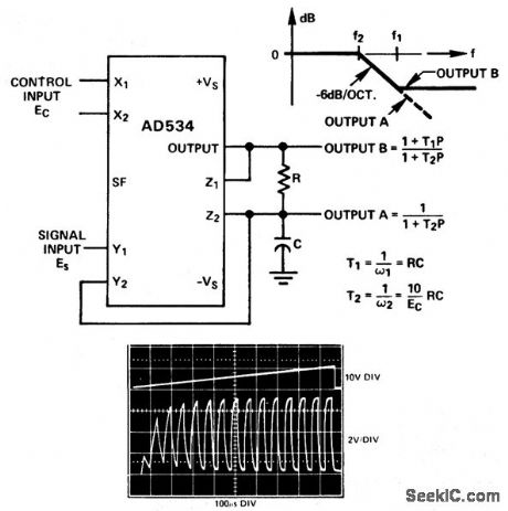
Voltage-controlled low-pass filter. The oscilloscope photo shows the circuit's response to a square wave with a ramp input. As an example if R is 8 K and C is 0.002 μF output A has a pole' frequency from 100 Hz to 10 kHz for Ea ranging from 100 mV to 10 V. Output B has an additional zero at 10 kHz. The circuit can be converted to a high-pass filter by interchanging C and R (courtesy Analog Devices, Inc.). (View)
View full Circuit Diagram | Comments | Reading(0)
Digitally_programmable_low_pass_filter
Published:2009/7/17 5:20:00 Author:Jessie
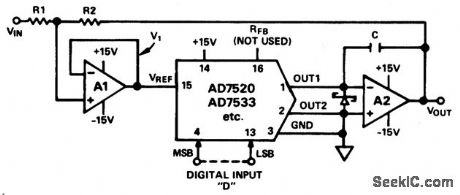
Digitally programmable low-pass filter. The two op amps are a AD747 (courtesy Analog Devices, Inc.). (View)
View full Circuit Diagram | Comments | Reading(806)
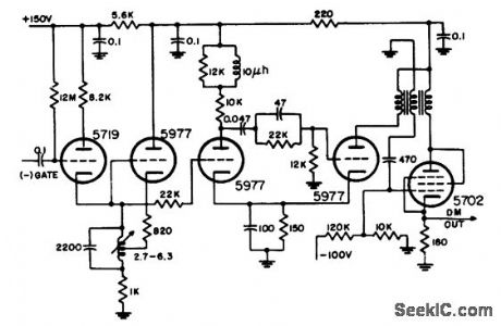
VARIABLE_TIME_INTERVAL_STANDARD
Published:2009/7/17 5:19:00 Author:Jessie
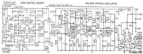
Produces two delayed pulses for establishing accurate time intervals from 1 to 10,000 microsec. Delays are adjustable in 1.microsec increments, with continuous interpolation between steps. Crystal-controlled oscillator and fast preset counters reduce time-delay errors. Useful in calibrating radar and loran timing circuits, oscilloscopes, and marker generators, as well as for precision pulse code modulation and for cadibrating delay lines.-D. Broderick, D. Hartke, and M. Willrodt, Precision Generator for Radar Range Calibrcation, Electronics, 32:14; p 58-60. (View)
View full Circuit Diagram | Comments | Reading(824)
Derivative_controlled_low_pass_filter
Published:2009/7/17 5:19:00 Author:Jessie
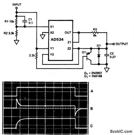
Derivative-controlled low-pass filter. This circuit settles rapidly in response to step changes, then assumes a long time constant for filtering noise. In the oscilloscope photo trace A is the input step, trace B is the control input and trace C is the signal output (courtesy Analog Devices, Inc.). (View)
View full Circuit Diagram | Comments | Reading(606)
BLOOD_VOLUME_SERVO
Published:2009/7/17 5:19:00 Author:Jessie
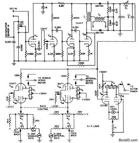
Servo-controlled pump with variable stroke drives blood from venous system of patient into artificial lung and after oxygenation returns it to arterial system. Control circuit insures that volume of blood is constant. Sensor is brass disk forming capacitance with pool of blood in oxygenator at spacing of 1mm. Error signal derived +tom capacitance change unbalances bridge that is energized at 3 kc (points B-B).Amplified error signal is applied to phase-sensitive demodulator. Unbalance energizes center-stable relays K1 and K2 of arterial and venous servo motors, so stroke output of arterial pump is decreased while that of venous pump is increased, or vice versa, to restore preselected volume of blood.-R. Schild and N. Wesson, Servo Circuit Controls Artificial Heart, Electronics, 31:15, p 73-75. (View)
View full Circuit Diagram | Comments | Reading(1075)
HARD_TUBE_MODULATOR
Published:2009/7/17 5:18:00 Author:Jessie
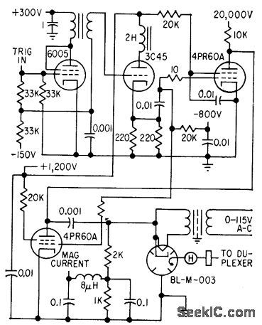
Supplies 0.02-microsec 180-kw modulating pulses at prf of 14,400 pps. Hard tube is used because hydrogen thyratron of adequate power-handling capability would not deionize rapidly enough at this prf.-R. F. P. Smith, Airport Radar Has High Resolution, Electronics, 32:14, p 64-69. (View)
View full Circuit Diagram | Comments | Reading(950)
RADAR_PULSER
Published:2009/7/17 5:16:00 Author:Jessie
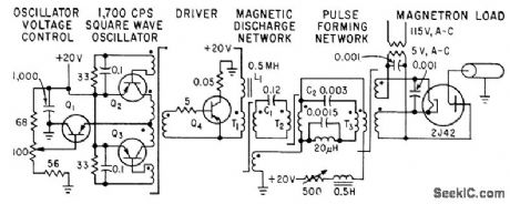
Magnetic discharge and pulse shaping networks are used instead of thyratrons or vacuum-tube amplifiers to re duce size und weight while increasing reliability.-A. Krinitz, Using Magnetic Circuits to Pulse Radar Sets, Electronics, 32:27, p 42-43. (View)
View full Circuit Diagram | Comments | Reading(869)
| Pages:107/291 At 20101102103104105106107108109110111112113114115116117118119120Under 20 |
Circuit Categories
power supply circuit
Amplifier Circuit
Basic Circuit
LED and Light Circuit
Sensor Circuit
Signal Processing
Electrical Equipment Circuit
Control Circuit
Remote Control Circuit
A/D-D/A Converter Circuit
Audio Circuit
Measuring and Test Circuit
Communication Circuit
Computer-Related Circuit
555 Circuit
Automotive Circuit
Repairing Circuit