
power supply circuit
Index 115
Attendance_counter
Published:2009/7/19 22:02:00 Author:Jessie
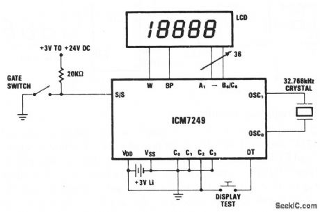
This circuit shows an ICM7249 connected as an attendance counter, with the LCD display showing each increment. The battery can be replaced without disturbing operation if a 100-μF capacitor is placed in parallel with the battery before removal. Disconnect the display (if possible) during the battery replacement. After replacement, the capacitor can be removed and the display can be reconnected. Harris Semiconductors Data Acquisition 1991 p, 11-90 (View)
View full Circuit Diagram | Comments | Reading(1763)
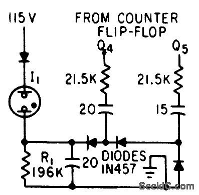
MULTIPLEX_DRIVER
Published:2009/7/19 22:01:00 Author:Jessie

Diode matrix drives bilateral transistors similar to core memory drivers. Drive circuit is regulated to within 10%. -J. V. Dirocco and J. W. Peghiny, Low.Level Encoding Approach; Latest Details of Titan II Telemetry, Electronics, 35:47, p 36-39.
(View)
View full Circuit Diagram | Comments | Reading(596)
8085_CPU_to_cassette_tape_recorder_interface_using_one_LM324_quad_op_amp
Published:2009/7/19 22:01:00 Author:Jessie


8085 CPU to cassette tape recorder interface using one LM324 quad op amp (courtesy Intel Corporation). (View)
View full Circuit Diagram | Comments | Reading(1355)
Motor_hour_meter
Published:2009/7/19 22:01:00 Author:Jessie
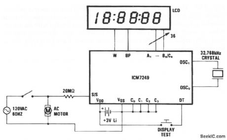
This circuit shows an ICM7249 that is connected as an hours-in-use meter and is capable of displaying how many hours that line voltage is applied to the motor. This configuration will operate continuously for 21/2 years using a 3-V lithium cell. Without the display (which only needs to be connected when a reading is required), the circuit will operate for about 10 years. Harris Semiconductors Data Acquisition, 1991. p 11-89 (View)
View full Circuit Diagram | Comments | Reading(1779)
Precision_frequency_counter
Published:2009/7/19 22:00:00 Author:Jessie
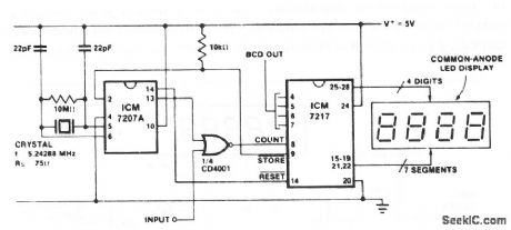
This circuit shows a simple 4-digit frequency counter using an ICM7217 and an ICM7207 (which provides the 1-s gating window and the STORE and RESET signals). The display reads hertz directly, as connected. With pin 11 of the ICM7027 connected to VDD, the gating time is 0. 1 s. This displays tens of hertz at the least significant digit. For shorter gating times, use a 6.5536-MHz crystal (0.01s with pin 11 connected to VD and 0.1 s with pin 11 open)
(View)
View full Circuit Diagram | Comments | Reading(2966)
G_M_COUNTER_FOR_TRACERS
Published:2009/7/19 22:00:00 Author:Jessie

Monitors radioactivity level of lowing liquids or gases for long periods of time. Concentration of 0.1 microcurie per liter of liquid gives counting rate of 200 cpm above 300-cpm background count when using iodine-131. Output pulse is 0.75 v in amplitude and 20 microsec wide.-F. E. Armstrong and E. A. Pavelka, Monitoring Radioisotope Tracers in Industry, Electronics, 32:26, p 42-43. (View)
View full Circuit Diagram | Comments | Reading(721)
WIND_VELOCITY_TRANSMITTER
Published:2009/7/19 21:59:00 Author:Jessie
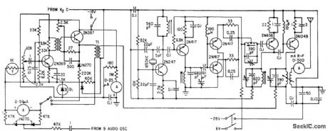
Batter-operated transmitter at remote mountctin site uses transmitters exclusively, for power econ to telemeter wind direction and velocity for predicting avalanches. Modulator uses nine separate 2N366 audio oscillators (not shown) that feed 2N369 class-A buffer.-R. Beaulieu and G. Neal, Wind Velocity Telemetering System, Electronics, 33:29, p 68-70.
(View)
View full Circuit Diagram | Comments | Reading(646)
4_to_20_mA_interface_using_the_454_V_F_converter_chip_with_a_10_kHz_full_scale_output
Published:2009/7/19 21:59:00 Author:Jessie
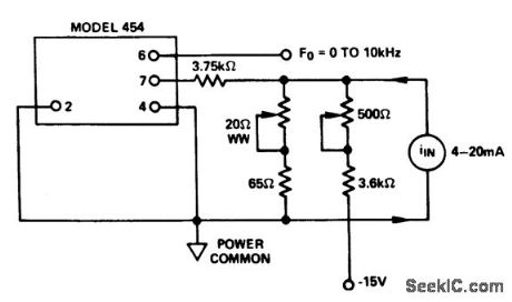
4-to-20 mA interface using the 454 V/F converter chip with a 10 kHz full scale output (courtesy Analog Devices, Inc.). (View)
View full Circuit Diagram | Comments | Reading(687)
8085_CPU_to_multiple_peripherals_interface
Published:2009/7/19 21:57:00 Author:Jessie
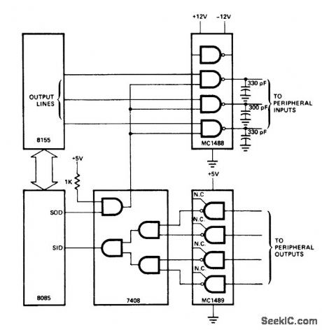
8085 CPU to multiple peripherals interface (courtesy Intel Corporation). (View)
View full Circuit Diagram | Comments | Reading(1191)
Simple_unit_counter_with_BCD_output
Published:2009/7/19 21:56:00 Author:Jessie
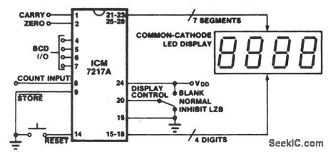
This circuit shows an ICM7217 and a calculator-type 4-digit display that is connected to form a very simple unit counter and display system. (View)
View full Circuit Diagram | Comments | Reading(1590)
Inexpensive_frequency_counter_tachometer
Published:2009/7/19 21:56:00 Author:Jessie
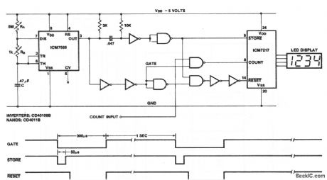
This circuit shows an ICM7217 and an ICM7555 that are connected as a basic frequency counter. The connections between the ICM7217 and a common-cathode LED display are shown in Fig. 12-18. The frequency counter is calibrated (against a known standard) using RA as a coarse control and RB as a fine control.Notice that the ICM7555 timer is connected as an astable multivibrator. Harris Semiconductors, Data Acquisition 1991 p 11 55 (View)
View full Circuit Diagram | Comments | Reading(4436)
GAMMA_RAY_DETECTOR
Published:2009/7/19 21:55:00 Author:Jessie
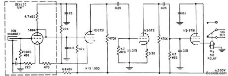
Triggers only on gammaray pulse produced by nuclear explosion. Uses a-c coupled ion chamber to detect pulses of gamma radiation.-J. C. Champeny, T. E. Petriken, and S. Siciliano, Nuclear Bomb Alarm Systems, Electronics, 32:19, p 53-55. (View)
View full Circuit Diagram | Comments | Reading(2353)
±15V_TRACKING_AT_100mA
Published:2009/7/19 21:55:00 Author:Jessie
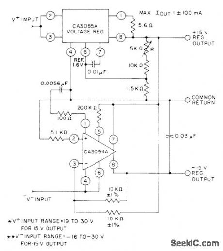
Provides line and load regulation of 0.075% by using CA3094A programmable opamp and CA3085A series voltage regulator. V+ input range is 19 to 30V for 15-V output, while V- input range is -16 to -30 V for -15 V output.- Circuit Ideas for RCA Linear ICs, RCA Solid State Division, Somerville, NJ, 1977, p 18. (View)
View full Circuit Diagram | Comments | Reading(735)
0_15V
Published:2009/7/19 21:54:00 Author:Jessie

Addition of 307 or 301A opamp and three inexpensive components to standard three-terminal voltage regulator provides programming capability from maximum terminal voltage down to zero. With adequate heatsink, output current can be up to 1A. Opamp A2 provides floating reference voltage to normally grounded common terminal of A1, with pot allowing ground to be positioned anywhere along voltage drop of 15V across pot. Unregulated negative supply is not critical, and drain is 10 mA.-W. G. Jung, Three Components Program Regulator from Maximum to Zero, EDN Magazine, May 20, 1977, p 126 and 128. (View)
View full Circuit Diagram | Comments | Reading(1135)
8080A_CPU_module_to_8255A_interface
Published:2009/7/19 22:32:00 Author:Jessie
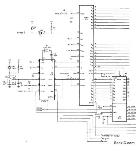
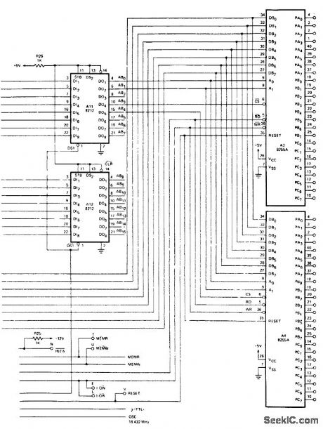
8080A CPU module to 8255A interface. This circuit comes complete as the Intel SDK 80 kit board. All of the 8255A interface lines are directly driven by the CPU (courtesy Intel Corporation). (View)
View full Circuit Diagram | Comments | Reading(1691)
RESONANT_REED_PAGING_RECEIVER
Published:2009/7/19 22:31:00 Author:Jessie
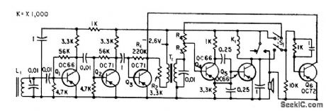
Fertile antenna L1 is tuned to one of up to 45 different carrier frequencies in range from 15 to 30 kc, keyed at various repetition rates. Resonant relay K1 in collector circuit of detector Q5 vibrates when excited at its natural keying rate, thereby interrupting loudspeaker current at audio rate to create paging tone.-J. G. DeGraaf, Selective Paging System Uses Coded Transmission, Electronics, 33:9, p 68-70. (View)
View full Circuit Diagram | Comments | Reading(713)
Simple_precision_barometer
Published:2009/7/19 22:30:00 Author:Jessie
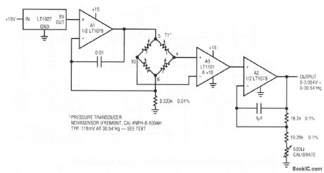
This circuit uses a semiconductor-based pressure transducer to form a low-cost simple barometer, and produces a 0- to 3.054-V output, in response to a sensed 0 to 30.54-in Hg. Transducer T1 specifies a nominal 115 mV at full scale, although each device is supplied with precise calibration data. To calibrate, adjust the potentiometer at A2 until the output corresponds to the scale factor that is supplied with the transducer. Linear Technology Corporation 1991 AN45-11
(View)
View full Circuit Diagram | Comments | Reading(978)
CURRENT_BOSTING_WITH_ELECTRONIC_SHUTDOWN
Published:2009/7/19 22:30:00 Author:Jessie
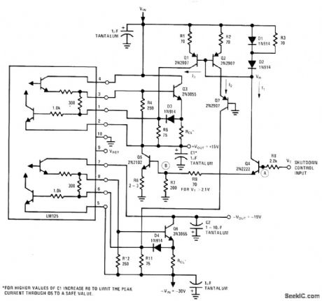
Circuit provides complete shutdown for both sections of National LM125 dual tracking regulator without affecting unregu-Iated inputs that may be powering additional equipment. Shutdown control signal is TTL-compatible, but regulator may be shut down at any desired level by adjusting values of R8 and R9. Control signal is used to short internal reference voltage of regulator to ground, thereby forcing positive and negative outputs to about +700 mV and +300 mV respectively. When shutdown signal is applied, Q4 draws current through R3 and D2, establishing voltage VR that starts current sourcesQ1 and Q2. Currents I1, I2, and I3 are then equal so both sides of regulator are shut down simultaneously.-T. Smathers and N. Sevastopoulos, LM125/LM126/LM127 Precision Dual Tracking Regulators, National Semiconductor, Santa Clara, CA, 1974, AN-82, p14. (View)
View full Circuit Diagram | Comments | Reading(750)
Battery_powered_relative_humidity_signal_conditioner
Published:2009/7/19 22:29:00 Author:Jessie
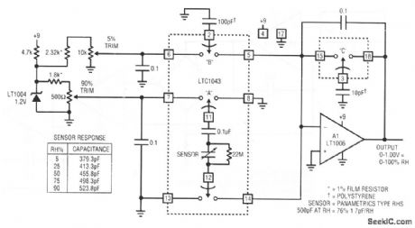
This circuit produces a 0- to 1.00-V output in response to a sensed 0 to 100% relative humidity (RH), and operates from a 9-V battery. To calibrate, place the sensor in a 5% RH environment, and set the 5% RH trim for 50 mV at the output. Then, place the sensor in 90% RH and set the 90% trim for 900-mV output.Repeat as necessary. If the known RH environments are not available, the capacitance-versus-RH table in Fig. 12-35 can be used (although the table applies to an ideal sensor). The capacitor values can be built-up or directly dialed on a precision variable air capacitor (General Radio #722D). Linear Technology Corporation 1991 AN45-10 (View)
View full Circuit Diagram | Comments | Reading(712)
RADIATION_ALARM_FAILURE_DETECTOR
Published:2009/7/19 22:28:00 Author:Jessie
Neon indicator lamp comes on when counter flip-flop of radioactive dust particle alarm stops. Flip-flop normally operates at minimum of 10 transitions per second due to slight leakage from radioactive test source built into detector.-H. E. DeBolt, How Radiation Monitor Guards Nuclear Navy, Electronics, 33:4, p 43-45. (View)
View full Circuit Diagram | Comments | Reading(795)
| Pages:115/291 At 20101102103104105106107108109110111112113114115116117118119120Under 20 |
Circuit Categories
power supply circuit
Amplifier Circuit
Basic Circuit
LED and Light Circuit
Sensor Circuit
Signal Processing
Electrical Equipment Circuit
Control Circuit
Remote Control Circuit
A/D-D/A Converter Circuit
Audio Circuit
Measuring and Test Circuit
Communication Circuit
Computer-Related Circuit
555 Circuit
Automotive Circuit
Repairing Circuit