
power supply circuit
Index 100
FIXED_CURRENT_REGULATOR
Published:2009/7/17 3:26:00 Author:Jessie
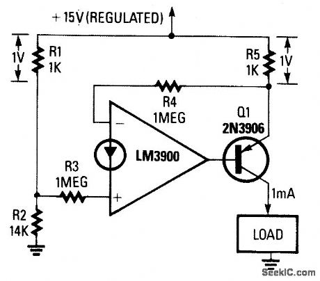
This ftxed 1-mA current source delivers a ftxed current to a load connected between Q1's collector and ground; the load can be anywhere in the range from 0 Ω to 14 Ω. The circuit is powered from a regulated 15-V supply, and the R1/R2 voltage divider applies a 14-V reference to R3. The op amp's output automatically adjusts to provide an identical voltage at the junction of R4 and R5. That produces 1 V across R5, resulting in an R5 current of 1 mA. Because that current is derived from Q1's emitter, and the emitter and collector currents of a transistor are almost identical, the circuit provides a fixed-current source. The output current can be doubled by halving the value of R5. (View)
View full Circuit Diagram | Comments | Reading(850)
COMMON_HOT_LEAD_REGULATOR
Published:2009/7/17 3:25:00 Author:Jessie
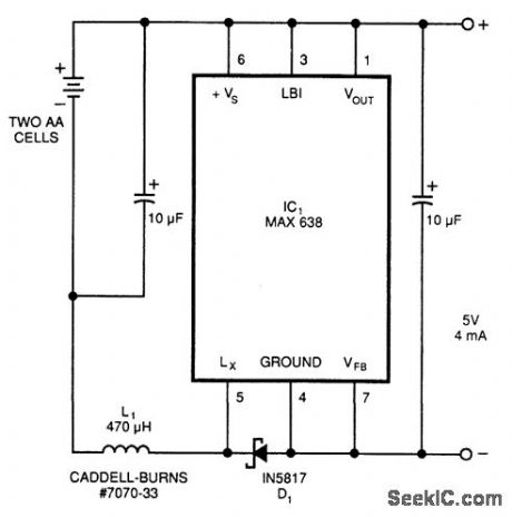
This circuit derives 5 Vdc from 2-AA cells-even at their end-life voltages of 1.05 V, and is approximately 80% efficient, providing 5 V at 4 mA from 2.1 V at 11 mA. IC1 is manufactured by Maxim Integrated Products, Inc. (View)
View full Circuit Diagram | Comments | Reading(622)
8_bit_parallel_adder_using_the_MC10181_
Published:2009/7/17 3:25:00 Author:Jessie

8-bit parallel adder using the MC10181 (courtesy Motorola Semiconductor Products Inc.). (View)
View full Circuit Diagram | Comments | Reading(2266)
32_bit_look_ahead_carry_adder_using_two_MC10179s_and_eight_MC10181_s
Published:2009/7/17 3:24:00 Author:Jessie
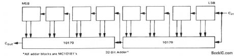
32-bit look-ahead carry adder using two MC10179s and eight MC10181 s(courtesy Motorola Semiconductor Products Inc.). (View)
View full Circuit Diagram | Comments | Reading(747)
MODEL_TRAIN_SOUNDER
Published:2009/7/17 3:23:00 Author:Jessie
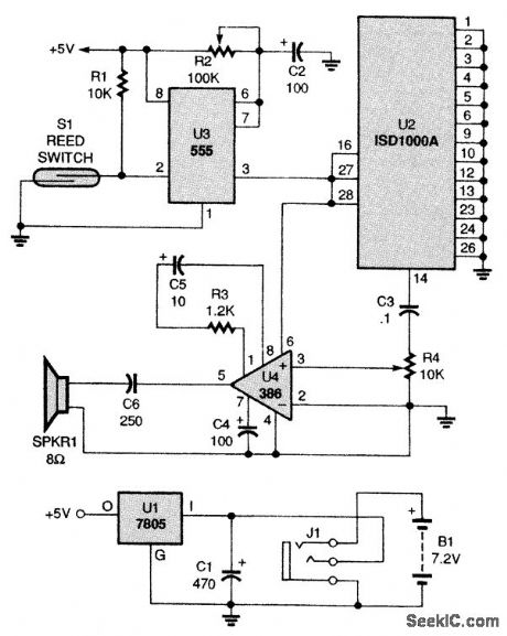
This circuit can fit inside a model-train car and output any sound that you record in the ISD1000A,Imagine a cattle car that moos! The circuit can be used in model railroading to sound an electronic diesel horn when the train approaches a railroad crossing It is mounted on the bottom of the car When the sound car approaches the Crossing,S1 is momentarily closed by a magnet that must be installed under the track,starting the timing Cycle and sounding the horn Before you can use U2,the ISD1000A record and playback IC, you must first program it by breadboarding the circuit found In the applications data included with the IC To record sound on U2,you'll need a sample of the sound that you want the IC to play.The phone jack, which is mounted on the bottom of the car, serves two purposes It serves alb a means of charging B1, the 7 2-V NiCd battery, and it also provides a way to turn the circuit off. (View)
View full Circuit Diagram | Comments | Reading(3375)
HIGH_OR_LOW_INPUT_REGULATOR
Published:2009/7/17 3:23:00 Author:Jessie
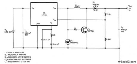
This regulator provides 12 V at 1 A out with an input voltage of 8 to 20 V. Output voltage can be changed by charging the 11-kΩ and 2.49-kΩ resistors to provide 2.21 V at the VFB pin of IC1, if desired. If you need to handle a higher input voltage, make sure to clamp the gate of Q1 below its 20-V max. rating.
Efficiency can exceed 70% for output currents greater than 0.5 A; above 15-V input voltage, more than 2 A of output current can be obtained. (View)
View full Circuit Diagram | Comments | Reading(1334)
VARIABLE_CURRENT_SOURCE0_TO_5A
Published:2009/7/17 3:23:00 Author:Jessie
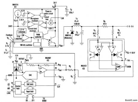
The variable-current source generates 0 to 5 A with a compliance range of 4 to 30 V. The 12-bit digital-to-analog converter (DAC), IC2, makes it digitally programmable. The switch-mode step-down regulator, IC1, is more efficient than the alternative current source with linear pass transistor.IC3 is a high-side current-sense amplifier. In this circuit, it senses output current as a voltage drop across R5, and produces a proportional signal current at pin 8. The regulator's feedback voltage (IC1 at pin 1) is set by the DAC and modified by IC3's current feedback, which flows across a parallel combination of R2 and R3. This current feedback opposes any change in load current because of a change in load resistance. The DAC generates 0 to 10 V, producing a source current that varies inversely with code: FFFHEX (10 V from IC2) produces 0mA, and 000HEX (0V from IC2) produces 5 A. The circuit can be reconfigured for other ranges of output current (Isource) by resizing R2 and R3:
Isource=2217[VFB(R2+R3)-(R3VDAC)]/R2R3
where VFB 2.21 V and VDAC can range from 0 to 10 V.
The desired range for Isource defines values for R2 and R3:VDAC=10V for the low value of Isource and VDAC=0V for the high value of Isource. Substituting these two sets of values in the equation yields two equations to be solved simultaneously for the values of R2 and R3. (View)
View full Circuit Diagram | Comments | Reading(1806)
16_bit_look_ahead_carry_adder_using_an_MC10179_and_four_MC10181_s_
Published:2009/7/17 3:23:00 Author:Jessie

16-bit look-ahead carry adder using an MC10179 and four MC10181 s (courtesy Motorola Semiconductor Products Inc.). (View)
View full Circuit Diagram | Comments | Reading(697)
NE602_MISER_CIRCUIT
Published:2009/7/17 3:20:00 Author:Jessie
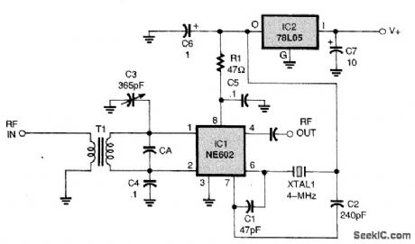
This circuit uses an NE602 as a mixer in a typical application Component values depend on operating frequency and are typical for a 4 MHz operation Note that no IF filter is shown in the RE output circuit,A filter is necessary to select the desired output product and reject the others (View)
View full Circuit Diagram | Comments | Reading(1267)
EFFICIENT_NEGATIVE_VOLTAGE_REGULATION
Published:2009/7/17 3:20:00 Author:Jessie
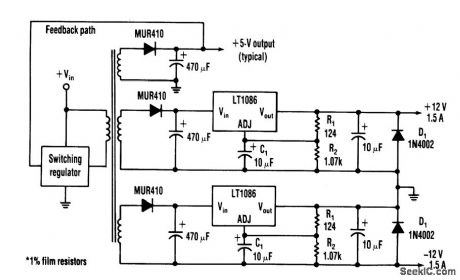
Many applications require highly efficient negative-voltage post regulators with low dropout voltage in switch-mode supplies.
A way to provide good negattve-vottage regulation is with a low-dropout positive-voltage regulator operating from a well-isolated secondary winding of the switch-mode transformer. The technique works with any positive-voltage regulator, although highest efficiency occurs with low-dropout types.
In the circuit, two programming resistors, R1 and R2, set the output voltage to 12 V, and the LT1086s servo the voltage between the output and its adjusting (ADJ) terminals to 1.25 V. Capacitor C1 improves ripple rejection, and protection diode D1 eliminates common-load problems.
Because a secondary winding is galvanically isolated, a regulator's 12-V output can be referenced to ground. Therefore, in the case of a negative-voltage output, the positive-voltage terminal of the regulator connects to ground, and the -12-V output comes off the anode of D1. The Vin terminal floats at 1.5 V or more above ground. This arrangement is the equivalent of connecting the positive terminal of a battery to ground and taking the output from the negative terminal. (View)
View full Circuit Diagram | Comments | Reading(1190)
AM_BROADCAST_BAND_PRESELECTOR
Published:2009/7/17 3:19:00 Author:Jessie
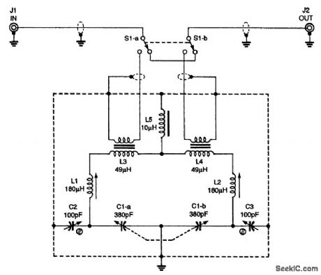
The circuit for the AM-BCB preselector is completely bilateral; for that reason, J2 could just as easily be the input jack. That makes connecting the unit to your receiver a breeze. Note that switch S1 can be set so that the unit is bypassed. (View)
View full Circuit Diagram | Comments | Reading(1535)
Phase_sensitive_detector_for_sinusoidal_signals
Published:2009/7/17 3:19:00 Author:Jessie
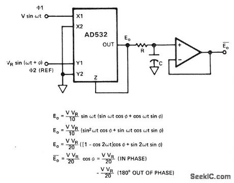
Phase-sensitive detector for sinusoidal signals. This circuit measures the magnitude of in-phase or 180°-out-of-phase inputs with the proper polarity, depending on the relationship to the reference with less than 1% error. The op amp shown is a AD741J (courtesy Analog Devices, Inc.). (View)
View full Circuit Diagram | Comments | Reading(3748)
TWO_CHANNEL_AUDIO_MIXER
Published:2009/7/17 3:19:00 Author:Jessie
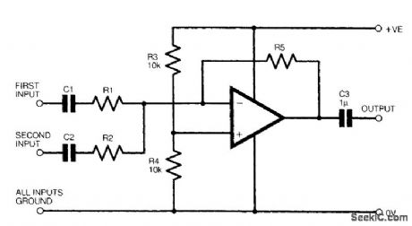
The figure shows a basic two-channel op-amp mixer circuit. The gain is equal to R5/R1 or R5/R2 for channel 1 or 2, respectively. Typically R1 and R2 are 2.2 to 22 kΩ and R5 is 10 to 100 kΩ, and the op amp is any suitable type, such as a 741 or its numerous variations. (View)
View full Circuit Diagram | Comments | Reading(3573)
Phase_sensitive_detector_with_square_wave_reference
Published:2009/7/17 3:18:00 Author:Jessie
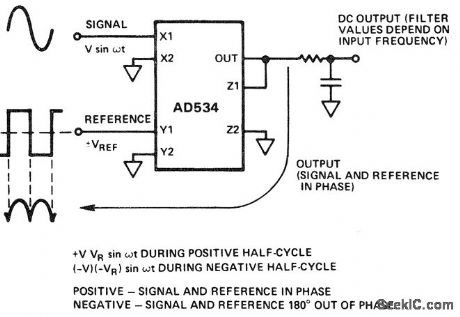
Phase-sensitive detector with square-wave reference. If the input and reference are in phase the output is positive. If they are 180° out of phase the output is negative (courtesy Analog Devices, Inc.). (View)
View full Circuit Diagram | Comments | Reading(3092)
AUDIO_MIXER
Published:2009/7/17 3:17:00 Author:Jessie
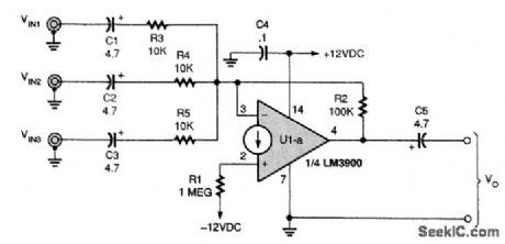
An audio mixer is a handy circuit that will combine two or more audio signal sources into one signal channel. The figure shows an audio mixer that is built around the LM3900 CDA. The crux of this circuit is the three input networks, principally R3, R4, and R5. These resistors are connected to different input sources (labeled VIN1,VIN2, and VIN3). Those three resistors all connect to the inverting input of the CDA. The gain is approximately
AV=R2/Rxwhere Rx is the value of any one input resistor. The output voltage is
Vo=R2[(VIN1/R3)+(VIN2/R4)+(VIN3/R5)If resistor R2 is made variable, then the potentiometer used for R2 will serve as a master gain control for the audio mixer. (View)
View full Circuit Diagram | Comments | Reading(8026)
pH_METER
Published:2009/7/17 3:16:00 Author:Jessie
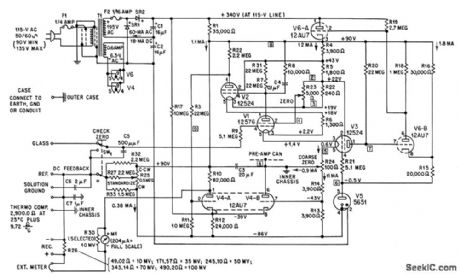
Beckman model W industrial-type pH meter is d-c amplifier designed for measuring potentials generated by pH-sensitive electrodes. Output will drive most recorders.R32 is used only with 4 to 14 pH meter, and R33 only with -1 to 9 pH meter.-G. C. Car. roll, Industrial Instrument Servicing Handbook, McGraw-Hill, N.Y., 1960, p 7-4. (View)
View full Circuit Diagram | Comments | Reading(2249)
Voltage_controlled_state_variable_filter
Published:2009/7/17 3:15:00 Author:Jessie
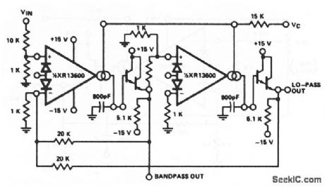
This circuit uses both sections of an XR-13600 (Fig. 11-1B) to form a state-variable filter (with both low-pass and bandpass outputs). EXAR corporation Databook, 1990 p,5-255 (View)
View full Circuit Diagram | Comments | Reading(985)
Missing_pulse_detector_using_an_ECG955M_timer_oscillator_chip
Published:2009/7/17 3:15:00 Author:Jessie
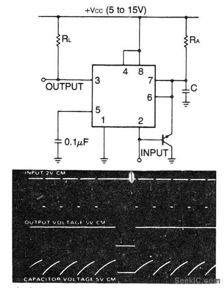
Missing pulse detector using an ECG955M timer/oscillator chip. The timing cycle is continuously reset by the input pulse train. A change in frequency or missing pulse allows completion of the timing cycle, which causes a change in the output level. The time delay should be set a little longer than normal between pulse for this reason (courtesy GTE Sylvania Incorporated). (View)
View full Circuit Diagram | Comments | Reading(989)
Frequency_shift_keyer_tone_generator_using_two_8_pin_DIPs_and_one_transistor
Published:2009/7/17 3:14:00 Author:Jessie
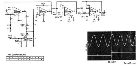
Frequency-shift keyer tone generator using two 8-pin DIPs and one transistor (courtesy GTE Sylvania Incorporated). (View)
View full Circuit Diagram | Comments | Reading(900)
TRANSISTORIZED_CHRONOTRON_MEASURES_COAX_DELAY
Published:2009/7/17 3:13:00 Author:Jessie
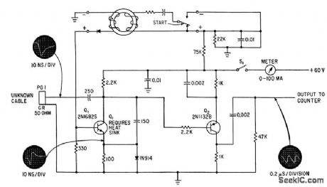
Start switch triggers avalanche transistor Q1, generating millimicrosec pulse that travels down unknown cable and returns to trigger new pulse. Digital counter is used to mesaure prr, which is proportional to cable delay. Q2 shapes counter pulse.-E. F. Laine, Getting Subnano-second Precision in Coax Cable Delay Measurements, Electronics, 36:5, p 39-41. (View)
View full Circuit Diagram | Comments | Reading(1290)
| Pages:100/291 At 2081828384858687888990919293949596979899100Under 20 |
Circuit Categories
power supply circuit
Amplifier Circuit
Basic Circuit
LED and Light Circuit
Sensor Circuit
Signal Processing
Electrical Equipment Circuit
Control Circuit
Remote Control Circuit
A/D-D/A Converter Circuit
Audio Circuit
Measuring and Test Circuit
Communication Circuit
Computer-Related Circuit
555 Circuit
Automotive Circuit
Repairing Circuit