
power supply circuit
Index 80
NEGATIVE_BUCK_REGULATOR
Published:2009/7/16 20:44:00 Author:Jessie
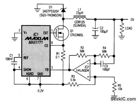
This circuit adopts a step-up (boost) dc-to-dc controller for use in a negative buck-regulator application. The supply voltage must be negative, and it must deliver 160 to 750 mA. Although the boost-regulator IC operates in a buck-regulator circuit, its standard connections enable proper control of Q1. The output voltage, however, must be inverted by an op amp for proper voltage feedback: The load is referred to the most positive supply rail instead of to 101's ground terminal, so the controller must increase its duty cycle as Vout (referred to that terminal) increases. The op amp there-fore inverts the feedback Signal and shifts it to match the 1.5-V threshold internal to IC1. IC1 is configured in its nonbootstrapped mode, which provides an adequate gate-drive signal (ground to -5.2 V) for the external MOSFET (Q1). With Vout set to -3 V and the output current ranging from 160 mA to above 700 mA, the circuit's conversion efficiency ranges from 84 percent to as high as 87.5 percent. (View)
View full Circuit Diagram | Comments | Reading(1536)
STRETCHING_FAST_PULSES_BY_SAMPLING
Published:2009/7/16 20:43:00 Author:Jessie
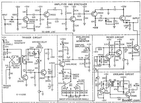

Attachment for conventional scope samples instantaneous amplitude of signals at different instants of time and reconstructs original shape by peak-detecting amplified and stretched samples. Permits resolving pulse rise times as short as 1/3nanosecond with repetition rates up to 50 kc.-J.J. Amodei, Converting Oscilloscopes for Fast Rise Time Sampling,Electronics,33:26,p 96-99. (View)
View full Circuit Diagram | Comments | Reading(937)
FOCUS_COLT_REGULATOR
Published:2009/7/16 20:36:00 Author:Jessie
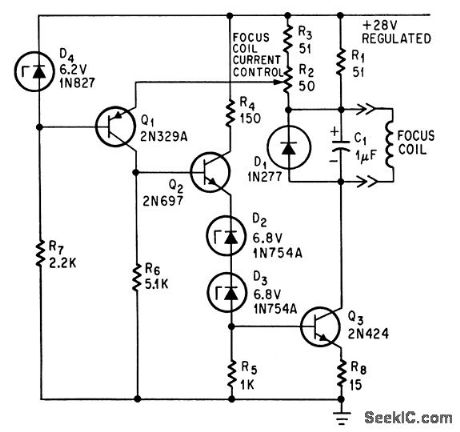
Regulation is 0.5% for current range of 220 to 270 ma, for magnetic focus coil of crt, between 25℃ and 65℃.-A.E. Popodi, Reliable Repertoire Of Display Circuits,Electronics,38:2,p 60-66. (View)
View full Circuit Diagram | Comments | Reading(746)
Z_AXLS_MARKER_GENERATOR
Published:2009/7/16 20:32:00 Author:Jessie
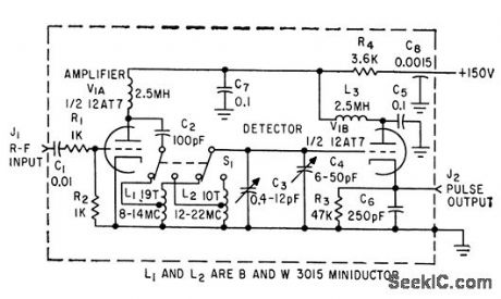
Circuit provides high-intensity dot marker on trace at any desired frequency in range from 8 to 22 Mc, in two overlapping ranges, with better than 1% long-term accuracy. Z-axis pulse is generated when external swept r-f oscillator passes through frequency to which tank circuit is tuned.-D.J. Odorizzi, Z-Axis Marker Generator for Bandpass Circuit Alignment, EJectronics,33:26,p 108-110. (View)
View full Circuit Diagram | Comments | Reading(867)
HIGH_VOLTAGE_FOR_PORTABLE_CRO
Published:2009/7/16 20:28:00 Author:Jessie
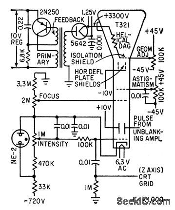
Derives 3.3 kv for post-accelerating anode from 20-kc high-voltage oscillator supply.-O. Svehcug and J. R. Kobbe, Banery-Operated Transistor Oscilloscope,Electronics, 33:12, p 80-83. (View)
View full Circuit Diagram | Comments | Reading(1094)
DEFLECTING_22_INCH_CRT_AT_50_KC
Published:2009/7/16 20:26:00 Author:Jessie
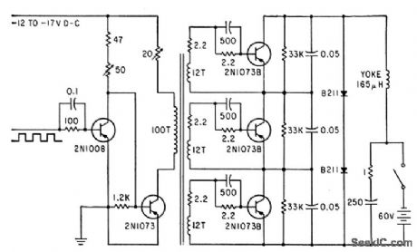


Circuit provides 5-amp peak-to-peak yoke current for full 70°defleaction of analog computer display. Rapid collector turnoff minimizes retrace lime. two B-211 diodes,series-connected as dampers,must be matched for voltage division.-R.S. Hartz and R. C. Allen, Reliable Circuit Supplies High Peak Deflection Voltages:EIectronics, 35:41,p 54-55. (View)
View full Circuit Diagram | Comments | Reading(925)
CRO_SWEEP_TRIGGER
Published:2009/7/16 20:22:00 Author:Jessie
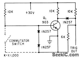
Base of Q1 is grounded once during each revolution by commutator segment of gyro balancer, to make circuit produce sharp pulse that triggers oscilloscope sweep.-F. W. Kear, Electronic System for Balancing Gyro Wheels, Electronics, 33:43, p 82-85. (View)
View full Circuit Diagram | Comments | Reading(1040)
CRO_LEVEL_CONTROLLED_STROBE
Published:2009/7/16 20:20:00 Author:Jessie
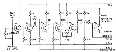
Variable input level determines part of telemetry signal that is selected for cathode-ray display.Output of Schmitt trigger Q2-Q3 is square wave with repetition rate determined by time-base frequency, and mark-space ratio controlled by variable d-c level input.-A. D. Runnalis, Bluebird Racer's Telemetry System,Electronics, 33:44, p 70-72. (View)
View full Circuit Diagram | Comments | Reading(857)
PROGRAMMABLE_CURRENT_SOURCE
Published:2009/7/13 0:04:00 Author:May
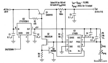
Constant-current Sources are required in many applications,particularly when it comes to battery charging in such applications,it is desirable that the output current be accurate,temperaturestable,and adjustable The controller also can be successfully employed as the control element in a low-cost linear current source.Output current is sensed by resistor R1,with the value selected so that 100 mV is full-scale The voltage across R1 is amplified by a factor of 10 and averaged across capacitor C4.AN internal transconductance error amplifier compares the voltage on pin 8 against the programming voltage at pin 7.The error-amplifier outputis present on pin 2 (Iout),and is level-shiftedby Q2 to control the PNP pass transistor Output current is programmed by adjusting the voltage across R5 (1 V full-scale).The LT1121 LDO regulator provides a 5-V,±1.5 percent reference voltage so that current can be accurately programmed by simply connecting different values for Rprog. The input voltage can range from +6 to +28 V, with output current changing less than 0.3 percent Properheat sinking must be provided for Q1, especially when operating with large input-to-output voltage differentials.Transistor Q3 and R4 limit the magnitude of Q1's base drive during dropout,preventing excessive dissipation in driver transistor Q2 using voltage regulator IC2, the constant-currentSource operates directly from the unregulated input voltage. Pulling IC2's shutdown ptn lowturns off VCC to the entire circuit,and limits the reverse current drawn from the output to less than 25μA. (View)
View full Circuit Diagram | Comments | Reading(3188)
PULSE_COUNTING_CIRCUIT_FOR_SHAFT_ENCODERS
Published:2009/7/16 20:11:00 Author:Jessie
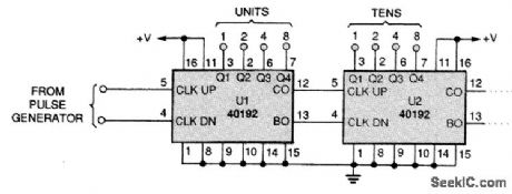
The output pulses of an encoding circuit can be counted with a BCD up/down counter such as the 40192. A binary-coded-decimal (BCD) number is produced. The counters have separate up and down clock inputs. For example, as long as the COUNT input (pin 11) is high, the counter will increment one count for every positive edge at the CLOCK-UP input (pin 5), and decrement one count for every positive edge at the CLOCK-DOWN input (pin 4). Counters can be cascaded by connecting the BORROW output (pin 13) to the following CLOCK-DOWN input and the CARRY output (pin 12) to the following CLOCK-UP input. (View)
View full Circuit Diagram | Comments | Reading(3520)
100_CPS_TO_1_MC_ASTABLE
Published:2009/7/16 13:08:00 Author:Jessie

Gives frequency change of 10,000 with reasonably good linearity over most of operating range. Two parts of timing cycle can be varied independently over wide range.-W. J. Mattox, A Versatile, Very-Wide Range Multivibrator, EEE, 13:7, p 59-61. (View)
View full Circuit Diagram | Comments | Reading(831)
2_W_WITH_LOW_PASS_FILTER
Published:2009/7/16 6:32:00 Author:Jessie
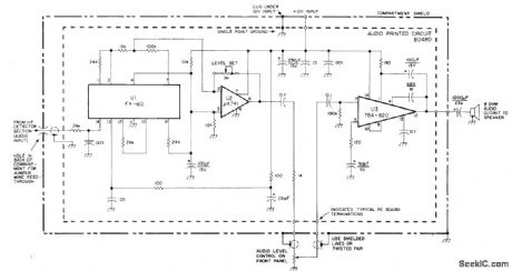
Developed for use in dual-conversion amateur receiver. Detected audio is passed through active low-pass filter-opamp arrangement U1-U2 and further amplified by 2-W audio amplifier U3. Simple voltage-divider circuit on pin 3 of U2 establishes artificial ground for U1 and U2. Low-pass rolloff starts at 2500 Hz, with about 20-dB attenuation of higher audio frequencies. IF heterodyne hiss is greatly attenuated and overall S/N ratio of receiver enhanced. Level-set 1-megohm pot between pins 2 and 7 of U2 establishes output gain for U1 and U2 together at about 0.8.-M. A. Chapman, High-Performance 20-Meter Receiver with Digital Frequency Readout, Ham Radio, Oct. 1977, p 48-61. (View)
View full Circuit Diagram | Comments | Reading(1026)
SIMPLE_FET_MIXER
Published:2009/7/16 6:18:00 Author:Jessie
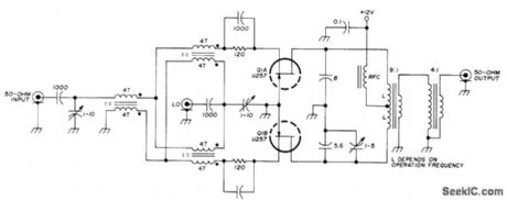
Uses U257 dual FET in double-balanced circuit having 50-ohm input impedance, for high-quality communication receiver. Gives excellent third-order intermodulation distortion suppression (68 dB down).-U.L Rohde, Optimum Design for High-Frequency Communications Receivers, Ham Radio, Oct. 1976,p 10-25. (View)
View full Circuit Diagram | Comments | Reading(1555)
ELECTRONIC_CAPACITOR
Published:2009/7/16 6:07:00 Author:Jessie

Two-terminal circuit provides capacitance values from 0.1 to 100 mfd, continuously variable in three ranges. Voltage ratting is +10 v and frequency range is d-c to 45 cps. Used in low-pass RC filter with adjustable cutoff frequency, in waveform analyzer.—D.L. Bergman, Electronic Capacitor is Continuously Variable, Electronics, 38:21, p 89 (View)
View full Circuit Diagram | Comments | Reading(1000)
12_VDC_TO_115_VAC_AT_100_W
Published:2009/7/12 23:44:00 Author:May
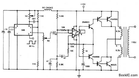
566 function generator provides triangleoutput at 60 Hz with frequency stability better than ±0.02%/°C. 540 power driver feeds six-transistor power output stage. Transformer load attenuates third harmonic, giving output very close to pure 60-Hz sine wave. 566 also provides square-wave out-put for other pu rposes.- Signet Ics Analog Data Manual, Signetics, Sunnyvale, CA, 1977, p853-854. (View)
View full Circuit Diagram | Comments | Reading(2052)
SENSING_CANE_FOR_BLIND
Published:2009/7/16 6:05:00 Author:Jessie

Capacitance-sensing probe in tip of cane changes frequency of one oscillator in accordance with distance from ground, curb, or holes, to make beat-frequency oscillator produce audio tone in headset worn by blind person.-J. Markus and V. Zeluff, Handbook of Industrial Electronic Control Circuits, McGraw-Hill, N.Y., 1956, p 24. (View)
View full Circuit Diagram | Comments | Reading(1253)
FLIP_FLOP_FOR_DATA_REGISTER
Published:2009/7/16 6:03:00 Author:Jessie
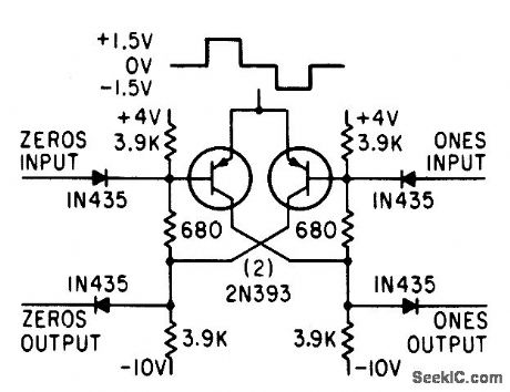
Eccles-Jordon type circuit uses surface-barrier transistors with saturation biasing. Large registers for computers are assembled by using one flip-flop per digit.-W. Orvedahl and J. H. Shepherd, Designing Data Registers with Simple Diode Circuits, Electronics, 36:8, p 48-50. (View)
View full Circuit Diagram | Comments | Reading(772)
DIRECT_CONVERSION_PRODUCT_DETECTOR
Published:2009/7/16 5:53:00 Author:Jessie
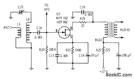
Antenna is matched to high-impedance gate input of JFET with resonant input transformer. Demodulating carrier is applied to same gate. RC filter and audio transformer in output circuit of JFET recover demodulating audio while filtering out RF signals and undesired mixing components.-E. M. Noll, FET Principles, Experiments, and Projects, Howard W. Sams, Indianapolis, IN, 2nd Ed., 1975, p 155. (View)
View full Circuit Diagram | Comments | Reading(2183)
PLATE_TO_GRID_COUPLED_MAIN_GATE_MVBR_
Published:2009/7/16 5:53:00 Author:Jessie
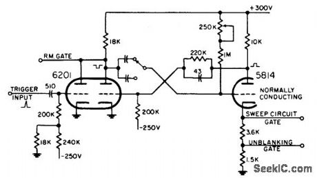
Used in combination search and gun-laying radar. Triggered by connecting plate of trigger inverter or switch tube in parallel with plate of normally-off mvbr tube. Provides positive unblanking gate for crt. Different gate lengths are obtained by switching mvbr capacitors.-NBS, Handbook Preferred Circuits Navy Aeronautical Electronic Equipment, Vol. 1, Electron Tube Circuits, 1963, p N10-2. (View)
View full Circuit Diagram | Comments | Reading(1011)
NEON_CRT_BIAS_REGULATOR
Published:2009/7/16 21:23:00 Author:Jessie
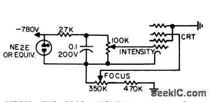
Neon lamp serves as bias regulator for grid 1 of oscilloscope crt and as pilot lamp.-More Glow-Lamp Circuits, EEE, 12:2, p 106-108. (View)
View full Circuit Diagram | Comments | Reading(935)
| Pages:80/291 At 206162636465666768697071727374757677787980Under 20 |
Circuit Categories
power supply circuit
Amplifier Circuit
Basic Circuit
LED and Light Circuit
Sensor Circuit
Signal Processing
Electrical Equipment Circuit
Control Circuit
Remote Control Circuit
A/D-D/A Converter Circuit
Audio Circuit
Measuring and Test Circuit
Communication Circuit
Computer-Related Circuit
555 Circuit
Automotive Circuit
Repairing Circuit