
power supply circuit
Index 77
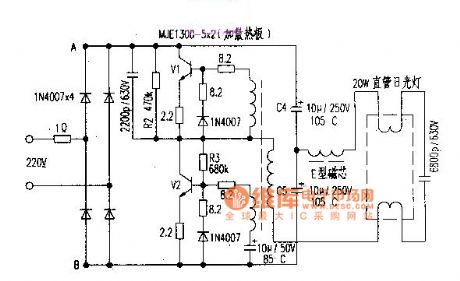
20W fluorescent lamp electronic ballast with with MJE13005×2 circuit diagram
Published:2011/8/4 20:04:00 Author:Rebekka | Keyword: electronic ballast, 20W fluorescent lamp
View full Circuit Diagram | Comments | Reading(3641)
3_kV_SUPPLΥ
Published:2009/7/13 3:15:00 Author:May
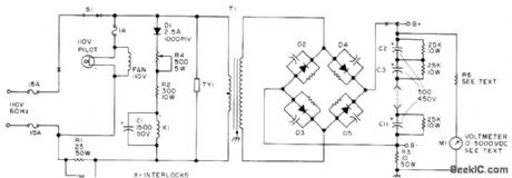
Circuit uses full-wave bridge rectifier D2-D5, with each diode stack constructed from two 1000-PIV 2.5-A diodes in series. Each diode pair is shunted by 470K 1-W resistorand 0.01-μF 1000-V disk capacitor C2-C11 are 500 μF at 450 VDC. Capacitor combination thus gives equivalent of 50 μF for filter, rated 4500 V. When using 500-μA movement for output voltmeter, R5 should be ten 1-megohm resistors in series. Thyrector TY1 is GE 6R52OSP4B4. T1 has 2200-V secondary rated 500 mA. K1 is 24-V relay. Article covers construction and stresses safety precautions.-E.H. Hartz, 3000 VDC Supply, 73 Magazine, July 1974, p 69-72. (View)
View full Circuit Diagram | Comments | Reading(1069)
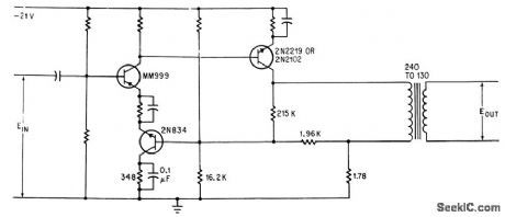
CHOPPER_DRIVING_SIGNAL_GENERATOR
Published:2009/7/16 3:53:00 Author:Jessie
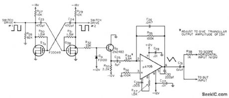
Dual mos fet and Fairchild 709 IC null amplifier are here used with 1-kc fee useable mvbr to develop the large voltage swings required to drive chopper of linear IC tester.-J. N. Giles, How to Measure Linear. IC Performance, EEE, 14:8, p 62-68 and 161 (View)
View full Circuit Diagram | Comments | Reading(803)
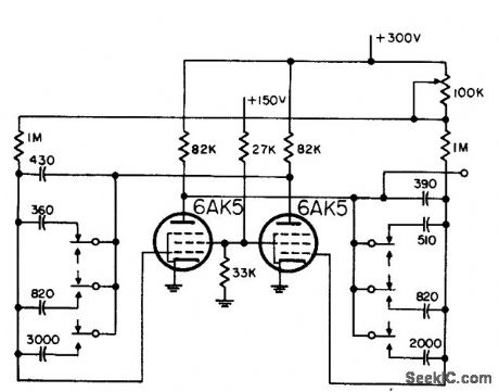
MAIN_GATE_MVBR_WITH_DIODE_LIMITER
Published:2009/7/16 10:19:00 Author:Jessie
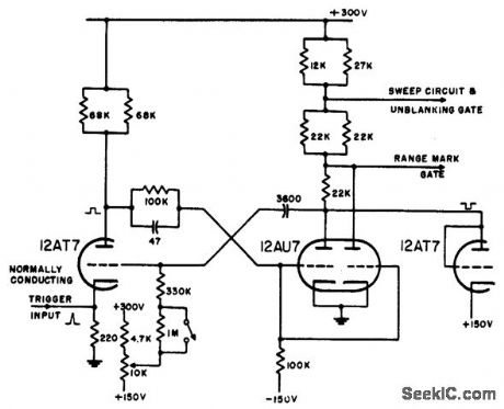
Diode-connected triode in parallel with output tube plate limits positive swing at this point. Circuit is triggered by blocking-oscil-lator pulse through normally-on tube cathode resistor.-NBS, Handbook Preferred Circuits Navy Aeronautical Electronic Equipment, Vol. 1, Electron Tube Circuits, 1963, p N10-4. (View)
View full Circuit Diagram | Comments | Reading(920)
200_400_AND_800_PPS_PRF_GENERATOR
Published:2009/7/16 10:18:00 Author:Jessie
Used in airborne radar. Frequency stability is 3% for 200 pps and 8% for higher frequencies, One drawback of mvbr here is that output impedance equals plate load resistance, which must be relatively high for good frequency stability.-NBS, Handbook Preferred Circuits Navy Aeronautical Electronic Equipment, Vol. 1, Electron Tube Circuits, 1963, p N5-1. (View)
View full Circuit Diagram | Comments | Reading(740)
10_MHz_FIXED_FOR_WWV
Published:2009/7/16 5:47:00 Author:Jessie
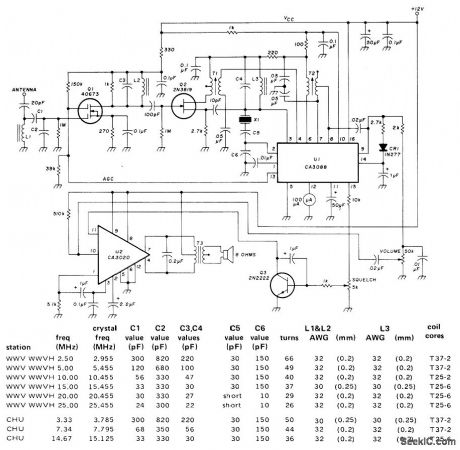
Fixed-frequency receiver has high sensitivity, portability, low power consumption, and low cost. Number of time parts is minimized by using RCA CA3088 IC for converter, lF, detector, audio preamp, AGC, and tuning-meter output, along with RCA CA3020 as audio amplifier. Table gives crystal frequencies and tuned-circuit values for all nine frequencies on which frequency calibration data, propagation forecasts, geophysical alerts, time signals, and storm warnings are broadcast by American and Canadian governments. Core type numbers are for Amidon Associates cores. IF transformers come as Radio Shack set 273-1383; use only T1 (gray core) and T2 (white core). Specify load capacitance as 32 pF when ordering crystals. Use overtone crystals for 20 and 25 MHz with C5 replaced by short and C6 reduced to 10 pF.-A. M. Hudor, Jr., Fixed. Frequency Receiver for WWV, Ham Radio, Feb.1977, p 28-33. (View)
View full Circuit Diagram | Comments | Reading(2490)
ULTRA_LONG_MONO
Published:2009/7/16 5:46:00 Author:Jessie
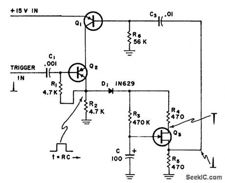
Has quiescent power drain of zero. Generates step-function gate with good leading and trailing edges, and provides delayed pulse of either polarity for triggering cascaded circuits. Q1 is 2N1442, scr Q2 is 2N1595 or 3A31, and ujt Q3 is 2N489. Values for R3 and C2 give 50-sec pulse duration.-Ultra-Long Monostable Multivibrator, Electronic Circuit Design Handbook, Mactier Pub. Corp., N.Y., 1965, p 66. (View)
View full Circuit Diagram | Comments | Reading(995)
INPUT_PULSE_UNBALANCES_BRIDGE
Published:2009/7/16 5:45:00 Author:Jessie
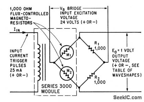
Trigger pulse causes opposite resistance variations in magnetoresistors M1 and M2, to give 1 v output for 25-ma pulse current.-R. M. Gitlin, Magnetoresistors Isolate Load From Control Circuit, Electronics, 38:3, p 60-61. (View)
View full Circuit Diagram | Comments | Reading(1046)
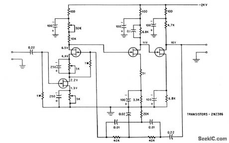
D_C_LEVEL_SHIFTER
Published:2009/7/16 5:43:00 Author:Jessie
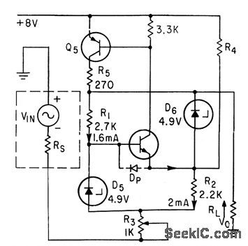
Bridge R1D5R2D6 and two transistors in d-c negative-feedback loop deliver output signal that is replica of input but at lower impedance and shifted in d-c voltage level a predetermined amount.-J. Willis, High Precision D-C Level Shifter Reduces Output Impedance, Electronics, 36:18, p 65-68. (View)
View full Circuit Diagram | Comments | Reading(1375)
TRANSISTOR_BRIDGE_SWITCHES_MICROVOLT_SIGNALS
Published:2009/7/16 5:42:00 Author:Jessie
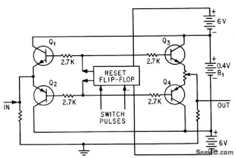
Circuit approaches infinite impedance during off condition by lowering emitter-to-collector conductance gap to zero. Conventional reset flip-flop controls on and off operation of series-connected npn and pnp bridge transistors. –M.V. Kalfaian, Transistor Bridge Switches Microvolts, Electronics, 37:1, p 60. (View)
View full Circuit Diagram | Comments | Reading(890)
CRYSTAL_PARAMETER_BRIDGE
Published:2009/7/16 5:41:00 Author:Jessie
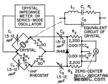
Bridge plugs into crystal socket of standard crystal impedance meter, and crystal under test plugs into bridge. Only other instruments needed for measuring equivalent parameters of overtone crystals for 75 to 200 Mc are frequency meter and null-indicating meter.-D. W. Robertson, Plug-in Bridge Checks VHF Quartz Crystals, Electronics, 31:19, p 82-85. (View)
View full Circuit Diagram | Comments | Reading(1338)
SELF_BALANCING_TORQUE_INDICATOR
Published:2009/7/16 5:40:00 Author:Jessie

Uses shunt bridge balancing technique. Amplifier and servo motor that drive 50-ohm balancing pot RB are standard commercial units. Highly stable power supply and reference voltage are not needed.-C. H. Haakana, Shunt Bridge Balancing in Strain-Gage Indicators, Electronics, 32:30, p 50-51. (View)
View full Circuit Diagram | Comments | Reading(990)
OPTOELECTRONIC_BRIDGE_ELEMENT
Published:2009/7/16 5:39:00 Author:Jessie
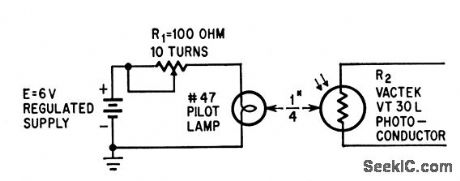
Lamp With rheostat varies resistance of photocell over range of 10,000 ohms to give stable nonreactive resistance element for r-f bridge. –R.H. Wagner, Variable R-F Resistor Attained With Photocell, Electronics, 37:26, p 67. (View)
View full Circuit Diagram | Comments | Reading(799)
CASCODE_ADDER
Published:2009/7/16 5:37:00 Author:Jessie
Gives gain of 600 when used as null detector of 400-cps impedance bridge, with measuring accuracy of one part per million.-W. A. Rhinehart and L. Mourlam, FET Performs Well in Balancing Act, Electronics, 38:19, p 88-92. (View)
View full Circuit Diagram | Comments | Reading(911)
DIODE_SAMPLING_BRIDGE
Published:2009/7/16 5:36:00 Author:Jessie
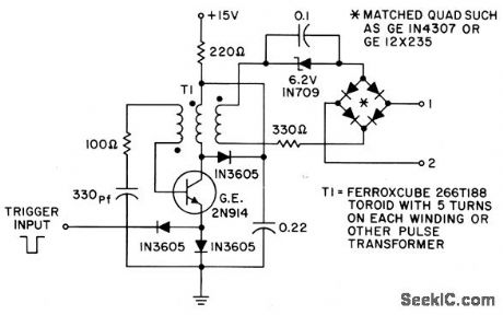
Uses diode matched quad with blocking-oscillator driving circuit. Negative input pulse triggers oscillator, generating pulse about 100 nsec wide, to forward-bias bridge diodes and reduce impedance between terminals 1 and 2 to about 5 ohms. Between pulses, diodes are reverse biased by capacitor charge and impedance between terminals rises to 1,000 meg.- Transistor Manual, Seventh Edition, General Electric Co., 1964, p 450. (View)
View full Circuit Diagram | Comments | Reading(2419)
FET_MIXER
Published:2009/7/16 5:36:00 Author:Jessie
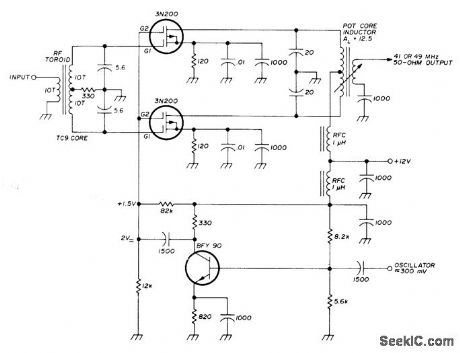
Double-balanced mixer developed for use in high-quality high-fidelity communication receiver has high input impedance (about 1000 ohms). Two-tone 176-mV signal produces third-order intermodulation distortion 68 dB down.-U. L. Rohde, Optimum Design for High-Frequency Communications Receivers, Ham Radio, Oct. 1976, p 10-25. (View)
View full Circuit Diagram | Comments | Reading(1740)
JAMMIX_STEREO_MIXER
Published:2009/7/16 5:35:00 Author:Jessie
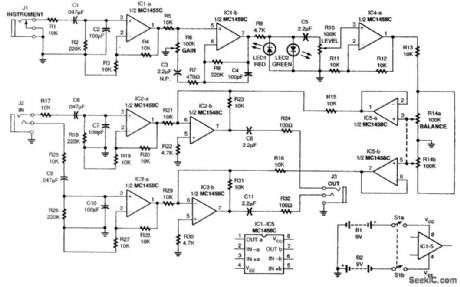
Here is the schematic diagram for JamMix. Note that nine out of ten sections from five MC1458C dual op amps are used. The INSTRUMENT jack, J1, provides a signal to IC1-a, which is a noninvert-ing buffer amplifier with a gain of 2. The gain is determined by R3 and R4. The amplified instrument signal is fed to audio-gain stage IC1-b, which is controlled by potentiometer R6. The circuit location of control R6 provides a desirable interplay with volume control on the guitar. Whenever the output of IC1-b exceeds about 2V p-p, light-emitting diodes LED1 and LED2 begin to illuminate and clip the audio signal, providing a high-quality distortion effect. The LEVEL control, RIO, sets the level of the output of the high-gain distortion stage IC4-a, which, in turn, drives the ganged potentiometers (R14a and R14b). Unity-gain amplifiers IC5-a and IC5-b feed summing amplifiers IC2-b and IC3-b, which in turn drive the external load connected to stereo OUT jack J3. The load can be either stereo headphones or additional external stages used for audio amplification. Integrated-circuit sections IC2-a and IC3-a are noninverting amplifiers, each with a gain of 2. Their inputs are the line-level stereo input signals, each having a gain of 2. Their outputs mix with the instrument signal in ampli-fiers IC2-b and IC3-b; both of these amplifiers also have a gain of 2. (View)
View full Circuit Diagram | Comments | Reading(1116)
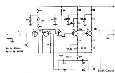
DIFFERENTIAL_BOOTSTRAP_AMPLIFIER_WITH_BRIDGE_FEEDBACK
Published:2009/7/16 5:35:00 Author:Jessie
Uses bridge feedback to give bandwidth of 30 to 300 kc with 40 db gain, for handling group of telephone channels as baseband amplifier.-N. A. Zellmer, Getting the Most Out of Feedback, Electronics, 39:2, p 66-72. (View)
View full Circuit Diagram | Comments | Reading(885)
DRAIN_COUPLED_ADDER
Published:2009/7/16 5:34:00 Author:Jessie
Gives gain of 1,400 for null detector of 400-cps impedance bridge, with measuring accuracy of one part per million.-W. A. Rhinehart and L.Mourlam, FET Performs Well in Balancing Act, Electronics, 38:19, p 88-92. (View)
View full Circuit Diagram | Comments | Reading(935)
PHASE_DIFFERENCE_BRIDGE
Published:2009/7/16 5:33:00 Author:Jessie
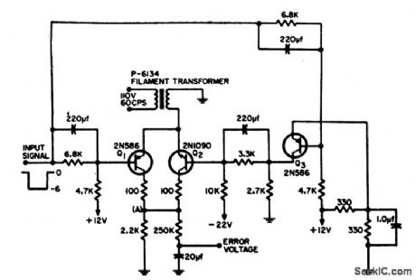
Develops d-c error voltage proportional to phase difference between two applied signals, one of which is 60-cps line-frequency reference. Can also correct oscillator outputs and serve as pulse-width discriminator.-D. P. Dorsey, Transistor Bridge Detector, EEE, 13:1, p 75. (View)
View full Circuit Diagram | Comments | Reading(923)
| Pages:77/291 At 206162636465666768697071727374757677787980Under 20 |
Circuit Categories
power supply circuit
Amplifier Circuit
Basic Circuit
LED and Light Circuit
Sensor Circuit
Signal Processing
Electrical Equipment Circuit
Control Circuit
Remote Control Circuit
A/D-D/A Converter Circuit
Audio Circuit
Measuring and Test Circuit
Communication Circuit
Computer-Related Circuit
555 Circuit
Automotive Circuit
Repairing Circuit