
power supply circuit
Index 67
The self-made NI-MH rechargeable battery circuit
Published:2011/8/15 21:34:00 Author: | Keyword: NI-MH rechargeable battery
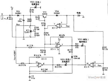
1.The form of Vref When the external power passes the outlet X and the diode VD1, it is then filtered by capacitor C1. VD1 fulfills the function of protection, it can prevent TL431 from being broken when the external power is connected reversely. R3 , R3, R4, R5 and TL431 form the Vref, according to the figured parameter Vref= 2.5×(100+820)/820=2.80(v), this data is designed for the Ni-MH rechargeable battery(the voltage of a NI-MH rechargeable cell is about 1.40V when it is full). 2.large current charge (1)the working principles When the power is on, the power supply indicator LED(VD2) is glowing. (View)
View full Circuit Diagram | Comments | Reading(1238)
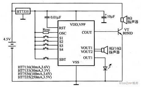
The 3.3V charge battery power supply applicational circuit
Published:2011/8/11 21:27:00 Author:Borg | Keyword: charge battery, power supply, applicational circuit

The 3.3V charge battery power supply applicational circuit is shown in the figure.
(View)
View full Circuit Diagram | Comments | Reading(731)
The 4.5V charge battery power supply applicational circuit
Published:2011/8/11 21:29:00 Author:Borg | Keyword: charge battery, power supply, applicational circuit
The 4.5V charge battery power supply applicational circuit is shown in the figure.
(View)
View full Circuit Diagram | Comments | Reading(963)
Regulator Power Circuit Using Luoya Improving Method
Published:2011/8/14 3:43:00 Author:Robert | Keyword: Regulator Power, Luoya, Improving, Method
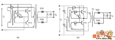
The picture shows the luoya improving method circuit. The picture (a) is suitable for the 220V input, while the picture (b) is suitable for the 380V input. For example in the circuit of picture (a), if firstly make the VT1 conducted by starting the resistor R1, the transformer T1 would have excitation and add the voltage on the transformer T2 through the current-limiting resistor R3. So the VT1 would be conducted rapidly. Then is the T1 is saturated, the VT1 would disconnected and at the same time the T2 would generate the opposing electromotive force and VT2 is conducted. So the VT1 and VT2 would make the oscillation by their alternate connected and disconnected work.
(a)Suitable for 220V input. (b)Suitable for 380V input.
The picture shows the luoya improving method circuit. (View)
View full Circuit Diagram | Comments | Reading(903)
A 24V WMOS tube regulated powers supply circuit
Published:2011/8/11 21:56:00 Author:Borg | Keyword: WMOS tube, regulated powers supply
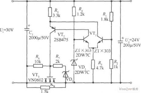
A 24V WMOS tube regulated powers supply circuit is shown as above.
(View)
View full Circuit Diagram | Comments | Reading(833)
The Fukang car ABS computer control circuit
Published:2011/8/11 7:31:00 Author:Borg | Keyword: Fukang, ABS, computer control circuit
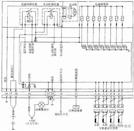
The Fukang car ABS computer control circuit (View)
View full Circuit Diagram | Comments | Reading(840)
The Fukang car ABS control circuit
Published:2011/8/11 8:10:00 Author:Borg | Keyword: Fukang, control circuit
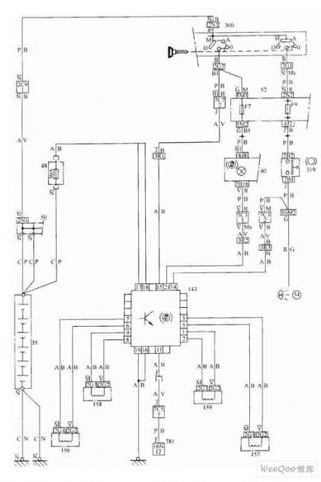
The Fukang car ABS control circuit (View)
View full Circuit Diagram | Comments | Reading(731)
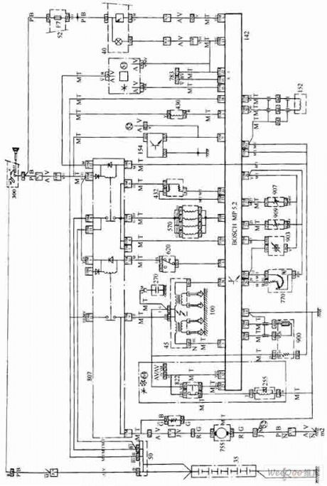
The Fukang car AL4 auto transmission electric control system circuit
Published:2011/8/11 8:12:00 Author:Borg | Keyword: Fukang, auto transmission, control system
The Fukang car AL4 auto transmission electric control system circuit (View)
View full Circuit Diagram | Comments | Reading(2144)
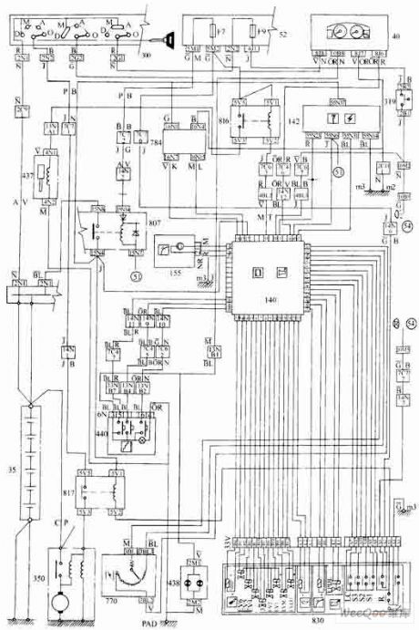
The Fukang car engine oil injection control system circuit
Published:2011/8/11 8:14:00 Author:Borg | Keyword: Fukang, engine oil, control system
The Fukang car engine oil injection control system circuit (View)
View full Circuit Diagram | Comments | Reading(990)
Automatic Ni-Cd Battery Charger Circuit Diagram
Published:2011/8/9 21:28:00 Author:Vicky | Keyword: Automatic Ni-Cd Battery Charger
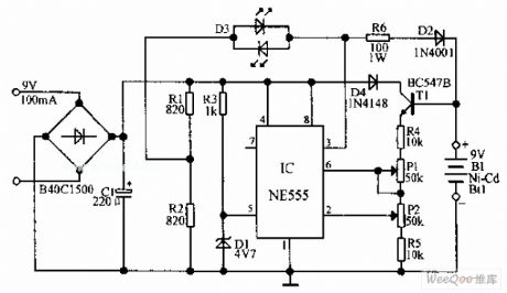
Automatic Ni-Cd Battery Charger circuit is shown in the above picture. The internal comparator of NE555 is set as 4.7V by Zener diode. If the potential of pin 6 becomes higher than this value, the output of pin 3 become lower; if the potential of pin 2 is lower than half of the reference voltage, the output voltage becomes higher,. When the voltage of the under-charging battery is very low, the output potential of the IC is high, the battery is charged via R6 and D2 until it’s full-charged. The voltage is set by P2, the state of output of IC is then changed, and the charging process stops. But IC still control the battery temporarily via T1. When the battery output reduces to the level set by P2 due to self-discharging, IC restart charging. (View)
View full Circuit Diagram | Comments | Reading(7047)
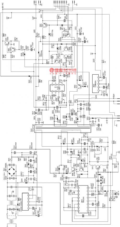
C7428 Power Supply Circuit Diagram
Published:2011/7/16 9:12:00 Author:Vicky | Keyword: Power Supply Circuit
View full Circuit Diagram | Comments | Reading(971)
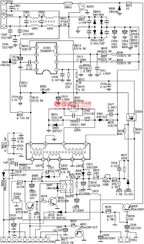
C7458 Power Supply Circuit Diagram
Published:2011/7/16 9:14:00 Author:Vicky | Keyword: Power Supply Circuit
View full Circuit Diagram | Comments | Reading(925)
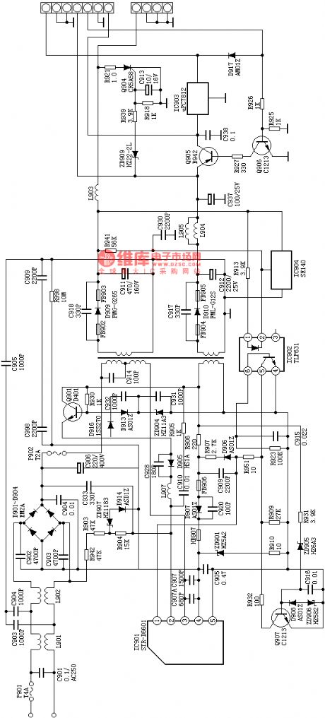
Hitachi AIPM8C Power Supply Circuit Diagram
Published:2011/7/16 9:17:00 Author:Vicky | Keyword: Hitachi, Power Supply Circuit
View full Circuit Diagram | Comments | Reading(862)
Pulsed dc electronic fishing device
Published:2011/7/18 6:37:00 Author:Christina | Keyword: Pulsed, dc, electronic, fishing device
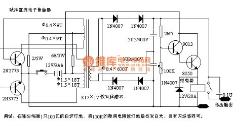
Debugging: you can connect a 100W incandescent lamp to the output port, you can adjust the 100K trimming resistance to make the lamp in the brightest state with the flashing feeling.
(View)
View full Circuit Diagram | Comments | Reading(1614)
Benchmark Voltage Power Supply Circuit of LM10
Published:2011/8/3 6:40:00 Author:Michel | Keyword: Benchmark Voltage, Power Supply Circuit
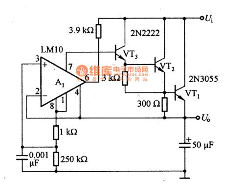
This benchmark voltage power supply circuit of LM10 is as above.LM10 can also work when it is ultralow voltage.In this circuit UBE voltage sum of series access transistor VT1,VT2 and VT3 are used as A1(LM10) work voltage.Whether series transistor is on or off,LM10 can also work,thus the voltage U。can be output.The maximum value of unstable input voltage Ui is determined by transistor. The voltage stability is 0.01%. Input voltage changes into + 10 V, voltage stability is ±0.1%. (View)
View full Circuit Diagram | Comments | Reading(1778)
Power Supply Circuit of LTC1422
Published:2011/8/3 7:02:00 Author:Michel | Keyword: Power Supply Circuit
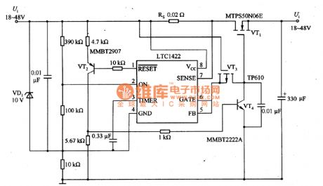
The power supply circuit of LTC1422 is as above.When the input voltage is connected,regulated diode VD1 controls the voltage of LTC1422 Vcc(8 feet) and Gnd(feet 4) and the voltage is 10V.GATE(feet 6)begins to output low PWL and it is connected to MOSFET(VT3) source.the gate of VT3 is connected to voltage Ui and the potential is higher than source,thus it can not be stopped.When the voltage on FB(feet 5) is lower than 1.232V.SET(comparator output end) pin turns into low PWL,VT2 and VT4 conducts,which makes the VT1 gate reach the ground.
For the minum timing cycle,ON pin becomes high PWL once and the charging pump begins to work and voltage on GATE pin rises in 1OμV/S slope.When the voltage on GATE pin rises to 1.232V,the voltage on FB pin rises, which makes the voltage on RESET pin rise and VT2 and VT4 conduct. (View)
View full Circuit Diagram | Comments | Reading(879)
DC power supply screen,DC cabinet
Published:2011/8/1 3:27:00 Author:chopper | Keyword: DC power supply screen, DC cabinet
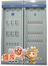
Field of application:GZDW series DC power supply cabinet is suitable for 10 ~ 500kV transformer substations, power plants and high-rise buildings, residential quarters and other power distribution rooms, and the small captive power plant, as high pressure switch, relay protection,and the automatic devices ,control power supply and emergency lighting power. Also it can be applied to other places needing DC power supply.
(View)
View full Circuit Diagram | Comments | Reading(925)
The practical simple battery automatic charger circuit
Published:2011/8/1 22:03:00 Author:TaoXi | Keyword: Practical, simple, battery, automatic charger

The circuit principle of the charger is as shown in figure 4-18. The 220V AC city electricity is transformed, rectified and filted by this circuit to output the 20V direct current, and this current charges the battery through the three-port voltage stabilizer. The switching circuit TWH8778 can be used to detect the two-end voltage of the battery.
When the charging starts, the voltage of battery is not enough to conduct the TWH8778, the equivalent circuit is as shown in figure 4-19(a). The constant current charges the battery, the constant current value I0=12.5/R, R is one resistance value of the R1-R4. When the battery voltage increases to the set value, the circuit of figure 4-19(b) is automatically converted into the circuit of 4-19(c).
(View)
View full Circuit Diagram | Comments | Reading(850)
The safe and reliable multi-function charger circuit
Published:2011/8/1 22:04:00 Author:TaoXi | Keyword: Safe, reliable, multi-function, charger
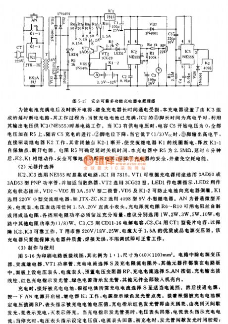

The principle diagram of this charger is as shown in figure 5-16. The 220V city electricity is reduced by the transformer T, and it is bridge rectified by the diodes VD1-VD4 to output the 17V, 100Hz pulsating DC voltage, this DC voltage can supply the power to the charging circuit. The DC current is stabilized by IC1 to supply power to the time-base integrated circuit IC2(NE555), so the IC2(NE555) produces the oscillation, we can use the pulse signal which is output by the pin-3 to control the conduction and cut-off of the darlington tube which is composed of the VT1 and VT2. This circuit has the RP, the electric potential of the adjustable port of it can be used to set the recharging the battery benchmark voltage.
(View)
View full Circuit Diagram | Comments | Reading(1050)
Clairvoyance charger (6V storage battery multi-function charger circuit)
Published:2011/7/26 20:10:00 Author:TaoXi | Keyword: Clairvoyance, charger, 6V, storage battery, multi-function, charger

The Clairvoyance charger circuit is as shown in figure 2-8, the unidirectional thyristor VS1 is used as the charge current tube of the storage battery GB, the VS2 can cut off the charging current when the storage battery is charging. When the power supply is charging, the relay K operates, the contact point 3 is connected with the contact point 2, the trigger port of VS1 gets the trigger voltage from the R1 and VD1 to conduct, the rectifier current charges the storage battery GB through the VS1. When the storage battery GB is charged to the set voltage, the VS2 conducts, so the VS1 trigger port point A's electric potential is lower than the cathode potential of VS2. VS1 cuts off, the storage battery GB stops charging. The LED can be used to show the charging.
(View)
View full Circuit Diagram | Comments | Reading(1105)
| Pages:67/291 At 206162636465666768697071727374757677787980Under 20 |
Circuit Categories
power supply circuit
Amplifier Circuit
Basic Circuit
LED and Light Circuit
Sensor Circuit
Signal Processing
Electrical Equipment Circuit
Control Circuit
Remote Control Circuit
A/D-D/A Converter Circuit
Audio Circuit
Measuring and Test Circuit
Communication Circuit
Computer-Related Circuit
555 Circuit
Automotive Circuit
Repairing Circuit