
power supply circuit
Index 66
Switch constant current power supply appliying circuit made by W723
Published:2011/8/10 23:29:00 Author:leo | Keyword: Switch, power supply, constant current
>
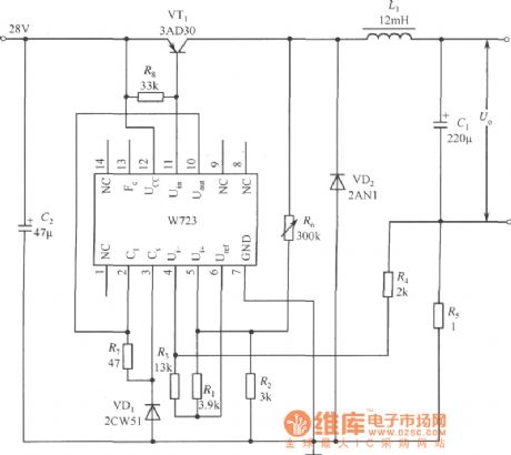
As the picture shows, it is a fixed current switch regulator applying circuit which is formed by W723. W723 is a multi-port adjustable positive integrated regulator. Its base voltage is about 7.2 V, which passes through R1 and R2 to add the 3V voltage to the input ports of the same phase. At the same time, the base voltage also passes through R3 and R4 to add the voltage to input ports of the negative phase. When the positive and negative phase input ports are balanced, voltage of R5 is about 1 V. (View)
View full Circuit Diagram | Comments | Reading(821)
The adaptive and adjustable regulated power supply made by LM317
Published:2011/8/6 22:40:00 Author:leo | Keyword: Adaptive circuit, adjustable circuit, regulated power supply
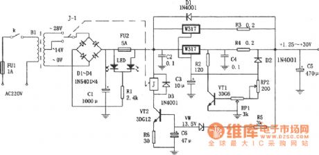
The picture shows a adaptive and adjustable regulated power supply. This power supply uses LM317 as the regulated component. Using this circuit to adjust the input voltage based on the output voltage which can reduce the voltage difference between input and output voltage to lower the power consumption of the power supply. VT2, VD5, VW, R5, R6, C10 and K form adaptive converting circuit. When the output voltage is lower than 14 V, VW, VT2 and K all stop and the 14 V voltage of transformer is connected to regulated circuit. Appositively, when output voltage is over 14 V, VM, VT2 and K are all working well, the transformer offers 28 V AC voltage to regulated circuit.
(View)
View full Circuit Diagram | Comments | Reading(2566)
Eliminating ripple IOV fixed voltage power supply circuit diagram
Published:2011/8/9 2:06:00 Author:Rebekka | Keyword: Eliminating ripple, IOV fixed voltage , power supply
View full Circuit Diagram | Comments | Reading(812)
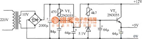
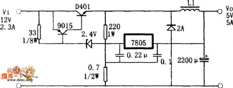
12V、5V Dual regulated power supply circuit diagram
Published:2011/8/4 21:43:00 Author:Rebekka | Keyword: 12V, 5V , Dual regulated power supply
View full Circuit Diagram | Comments | Reading(2900)
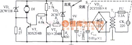
9V Tape Reader AC and DC Power Supply Circuit Diagram
Published:2011/8/9 2:05:00 Author:Rebekka | Keyword: 9V Tape Reader, AC and DC , Power Supply
View full Circuit Diagram | Comments | Reading(976)
5v Fixed power supply circuit diagram with short-circuit protection
Published:2011/8/9 2:22:00 Author:Rebekka | Keyword: short-circuit protection, fixed power supply
View full Circuit Diagram | Comments | Reading(1192)
5 V regulated power supply circuit diagram with doubler rectifier
Published:2011/8/9 2:21:00 Author:Rebekka | Keyword: 5 V , regulated power supply , doubler rectifier
View full Circuit Diagram | Comments | Reading(928)
4.5V Precision power circuit diagram
Published:2011/8/9 2:18:00 Author:Rebekka | Keyword: 4.5V Precision power
View full Circuit Diagram | Comments | Reading(879)
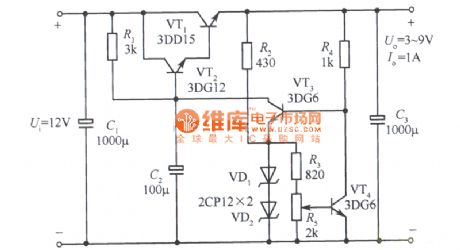
Adjustable regulated power supply circuit diagram with 3~9V sampling ratio
Published:2011/8/9 2:03:00 Author:Rebekka | Keyword: Adjustable, regulated power supply , 3~9V , sampling ratio
View full Circuit Diagram | Comments | Reading(1259)
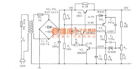
IOV fixed power supply circuit diagram with l20~250V grid voltage
Published:2011/8/9 2:01:00 Author:Rebekka | Keyword: Grid voltage , fixed power supply, l20~250V
View full Circuit Diagram | Comments | Reading(1403)
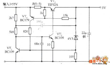
5V fixed voltage power supply circuit diagram with over cut-off protection
Published:2011/8/17 3:05:00 Author:Rebekka | Keyword: Over cut-off protection, fixed voltage power supply, 5V
View full Circuit Diagram | Comments | Reading(1223)
Regulated power supply circuit diagram composed of L296 monolithic high-current switching power supply chip
Published:2011/8/17 2:54:00 Author:Rebekka | Keyword: Regulated power supply , monolithic high-current , switching power supply chip
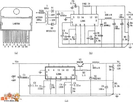
The features of L296 monolithic high-current switching power supply chip are: (1) Perfect protection function. It is equipped with soft start, over current, overheating, overvoltage protection; (2) The maximum output current is 4A, 160W power, output voltage is adjustable between 5.1 ~ 40V; (3) Special features: Workban control, synchronization control(in a few pieces long on output, to ensure the same frequency), reset circuit (power supply can provide state of the detection signal), crowbar overvoltage protection circuit(When the output voltage exceeds a preset 20% rated. It produces a 100mA of drive signals for triggering external protection circuit action). Figure (c) shows the current expansion of the circuit form. (View)
View full Circuit Diagram | Comments | Reading(4612)
TD4919 switch regulator power supply circuit diagram composed of switching power supply IC
Published:2011/8/17 2:38:00 Author:Rebekka | Keyword: switch regulator, power supply , switching power supply
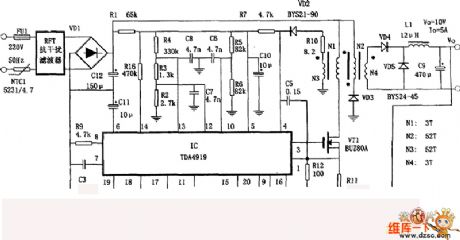
The AC input voltage of the circuit is 185~240V, DC output voltage is 10V, output current is 5A. The features are: It has the function of monitoring output voltage, overvoltage and undervoltage and the function of dynamic current limit.
Regulation process is: Output voltage Vo passes R15 and PR partial pressure trough R16 and R17 feedback to pin18 and pin 19 of TD4919. The internal control of TD4919 is used to adjust its output switch pulse duty cycle to reach a stable output voltage Vo. The monitor of power supply output current is realised by the sample voltage of R11 monitoring(R11 is the sample voltage of VT source current). It produces control signalto control the output switch pulse to achieve the limit of output current. Undervoltage and overvoltage monitoring is achieved by R4, R5, R6, pin12, pin13 and the internal control circuit of TD4919. (View)
View full Circuit Diagram | Comments | Reading(1573)
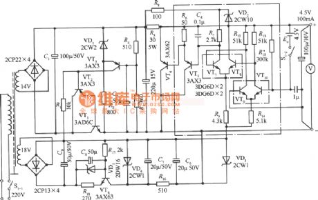
Switch regulator power supply circuit diagram made by three-terminal regulator
Published:2011/8/17 3:20:00 Author:Rebekka | Keyword: three-terminal regulator , switch regulator power supply
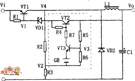
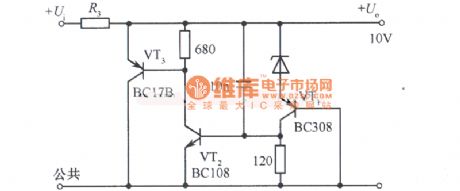
Equivalent circuit of switching regulator power supply:
Switch regulator power supply circuit diagram made by three-terminal regulator is shown as above. Itsworking principle can be read through the equivalent circuit diagram. The output voltage VO declines a little because of some reasons. The partial pressure V3 on R5 and R6 also declines. It is enlarged by VT3, then Ic3 minishes, Ic2 increases, the current passing R1 and VD1 increases, V1 declines. It makes Ic1 increase, V4 rise, V4 passing the partial voltage of R2 and R3, V2 increase and V3 decline. The process is a reaction of positive chain feedback. Finally VT1 and VT2 are conducted, VT3 stops, Ic1 charges to L1 and C1. It makes Vo increase gradually. (View)
View full Circuit Diagram | Comments | Reading(875)
The 24V regulated powers supply circuit with over-current protector
Published:2011/8/11 21:57:00 Author:Borg | Keyword: regulated powers supply, over-current protector
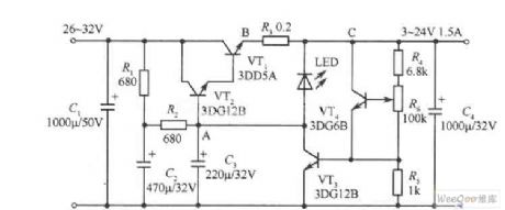
The 24V regulated powers supply circuit with over-current protector is shown as above.
(View)
View full Circuit Diagram | Comments | Reading(850)
A durable 0~20V regulated power supply circuit
Published:2011/8/11 21:59:00 Author:Borg | Keyword: regulated power supply
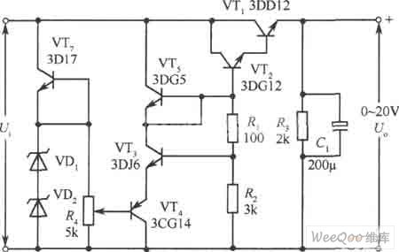
A durable 0~20V regulated power supply circuit is shown as above.
(View)
View full Circuit Diagram | Comments | Reading(1995)
A small-sized 15V and 1A parallel regulated power supply circuit
Published:2011/8/11 22:01:00 Author:Borg | Keyword: small-sized, parallel, regulated power supply
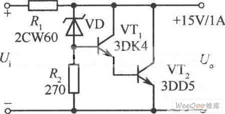
A small-sized 15V and 1A parallel regulated power supply circuit is shown as above.
(View)
View full Circuit Diagram | Comments | Reading(772)
Common 0~20v and 1A regulated power supply circuit
Published:2011/8/11 22:02:00 Author:Borg | Keyword: regulated power supply
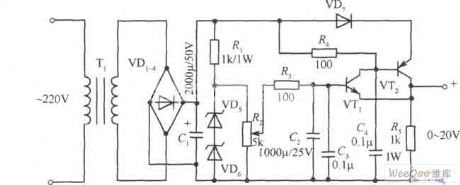
The common 0~20v and 1A regulated power supply circuit is shown as above.
(View)
View full Circuit Diagram | Comments | Reading(1090)
The Fukang engine igniter and relevant electric element control circuit
Published:2011/8/11 21:10:00 Author:Borg | Keyword: engine igniter, electric element, control circuit
The Fukang engine igniter and relevant electric element control circuit (View)
View full Circuit Diagram | Comments | Reading(686)
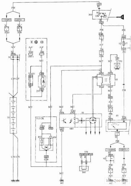
The Fukang charging and starting circuit
Published:2011/8/11 21:11:00 Author:Borg | Keyword: Fukang, charging, starting
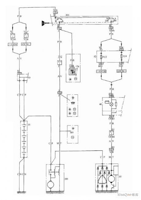
The Fukang charging and starting circuit (View)
View full Circuit Diagram | Comments | Reading(672)
| Pages:66/291 At 206162636465666768697071727374757677787980Under 20 |
Circuit Categories
power supply circuit
Amplifier Circuit
Basic Circuit
LED and Light Circuit
Sensor Circuit
Signal Processing
Electrical Equipment Circuit
Control Circuit
Remote Control Circuit
A/D-D/A Converter Circuit
Audio Circuit
Measuring and Test Circuit
Communication Circuit
Computer-Related Circuit
555 Circuit
Automotive Circuit
Repairing Circuit