
power supply circuit
Index 61
ZCS PWM DC/DC converter circuit diagram
Published:2011/9/7 4:08:00 Author:Vicky | Keyword: ZCS PWM DC/DC converter
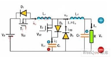
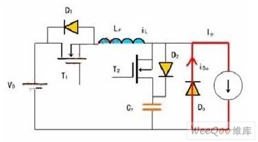
Topological structure: Buck DC/DC ZCS PWM converter, main switch T1 (including antiparallel diode D1), booster diode T2 (D2 is the antiparallel diode of T2).
Suppose thatthe diode switches are all ideal devices; the inductances and capacitances are all ideal components; Cr is big enough, Lf is also big enough, and Lf>>Lr. I switching cycle, output voltage is 0, remaining and unchanged; if it retains Io, unchanged, so Lf, Cf and load resistance can be regarded as a constant current source Io.
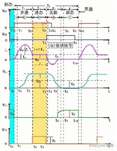
The state of switch: In a switching cycle Ts, converter has 5 switching state. Every switching state has a corresponding equivalence circuit. (View)
View full Circuit Diagram | Comments | Reading(3145)
Circuit diagram of 9V charger which can preset the end voltage of charging
Published:2011/9/7 4:00:00 Author:Vicky | Keyword: 9V charger, preset the end voltage of charging
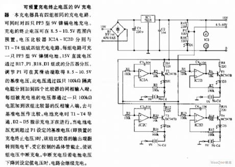
The picture is a circuit of 9V charger which can preset the end voltage of charging. The charger has four groups of identical charging circuit, which can charge four pieces of PP3 type 9V nickel-cadmium battery at the same time. The end voltage can be set between 8.5 to 10V. The voltage comparators IC2A~IC2D constitute four groups of charging circuit with T1~T4 respectively. Every circuit can charge a PP3 type 9V nickel-cadmium battery. 15V DC voltage is divided by voltage divider composed of R17, P1, R18, and D1. The base voltage of 8.5~10V can be gained in the sliding end by adjusting P1. The voltage is added to non-inverting input ends of the four comparators by four 100KΩ isolation resistance. The voltage of every group charged is added to inverting end of its corresponding comparators via a 100KΩ resistance to compare with the base voltage. (View)
View full Circuit Diagram | Comments | Reading(2140)
Express charger circuit diagram
Published:2011/9/7 3:58:00 Author:Vicky | Keyword: Express charger circuit
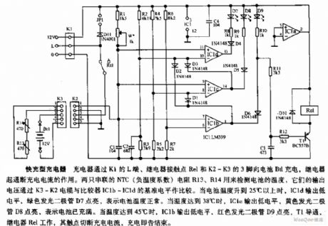
Express charger circuit diagram
The charger charges Bt1via the Lend of K1, contact point Rel of relay, and pin 3 of K2-K3, while the relay acts to control on-off of the charging current. Two NTC (negative temperature coefficient) resistances R13 and R14 in serial are used to examine the temperature of battery. Their output voltage compares with the base level of comparators IC1b ~IC1d via wire cable K3 ~ K2. When the battery temperature rises to above 25℃, IC1d outputs low level, and the green luminous diode D7 is lighted to show that the battery temperature is normal. When the temperature rises to 38℃, IC1c outputs low level, and yellow luminous diode D8 is lighted to show that the battery is full charged. When the temperature rises to 45℃, IC1b outputs low level, the red luminous diode D9 is lighted, T1 is conducted, relay Rel starts working with its contact point cutting off the charging current, and the charging ends. (View)
View full Circuit Diagram | Comments | Reading(1476)
Regulator DC-DC Circuit and Pin of Power Supply Monitor and its Main Features TA7501S Amplified Circuit
Published:2011/9/6 2:57:00 Author:Zoey | Keyword: Regulator, DC-DC Circuit, Pin of Power Supply Monitor, Amplified Circuit
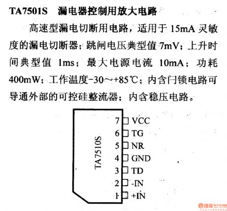
TA7501S Amplified Circuit controlled by Leakage Current
The circuit that can be cut off by high-speed leakage current is available for leakage cutters,which have a sensitivity of 15mA. The typical value of trip voltage is 7mV and it will turn to be 1ms when it increases. The maximum current of the power supply is 10mA and the power is 400mW. The working temperature is between -40 ℃to +85℃. The lock circuit itself has an interior voltage stabilizing circuit and an interior SCR rectifier that can conduct externally. (View)
View full Circuit Diagram | Comments | Reading(789)
Regulator DC-DC Circuit and Pin of Power Supply Monitor and its Main Features TA7179P Tracking Regulator
Published:2011/9/6 2:57:00 Author:Zoey | Keyword: Regulator, DC-DC Circuit, Pin of Power Supply Monitor, Main Features, Positive output
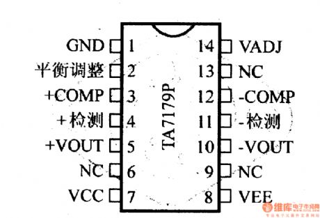
TA7179P tracking regulator can output±15V voltage, and this value can be turned to be±8V by using VADJ terminal and external resistance. The current output is 100mA and the temperature drift is 0.007%/℃,the maximum voltage output is ±30V. (View)
View full Circuit Diagram | Comments | Reading(2190)
Regulator DC-DC Circuit and Pin of Power Supply Monitor and its Main Features TA7089P Compressible Regulator(Positive Output)
Published:2011/9/6 3:00:00 Author:Zoey | Keyword: Regulator, DC-DC Circuit, Pin of Power Supply Monitor, Compressible Regulator(Positive Output)
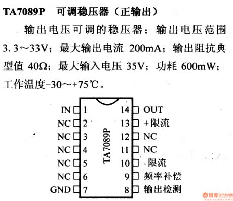
TA8909 adjustable regulator(Positive output) can output adjustable voltage, which ranges from 3.3V to 33V. The maximum current output is 200mA and the typical value of impedance output is 40Ω. The maximum voltage input is 35V, with the power of 600mW. The working temperature is between -30℃ to +75℃. (View)
View full Circuit Diagram | Comments | Reading(1293)
Regulator DC-DC Circuit and Pin of Power Supply Monitor and its Main Features SI-3000C Regulator
Published:2011/9/6 2:58:00 Author:Zoey | Keyword: Regulator, DC-DC Circuit, Pin of Power Supply Monitor, Positive Output
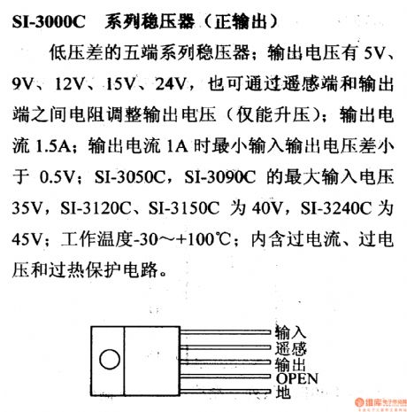
SI-3000C series regulators(positive output ) are five-terminal regulators that have low voltage margins. The voltage output can be 5V, 9V, 12V, 15V and 24V. The outout voltage can also be adjusted by the resistance between remote sensing terminal and output terminal. The output current is 1.5A and the output voltage margin can decrease to less than 0.5V when the current turns to be 1A. Maximum output voltage of SI-3050C and SI-3090C is 35V, SI-3120C and SI-3150C 40V, SI-3240C 45V. The working temperature is between -30℃to +100℃.Each of themhas an interior overcurrent, overvoltage and overtemperature-proof circuit. (View)
View full Circuit Diagram | Comments | Reading(941)
Regulator DC-DC Circuit and Pin of Power Supply Monitor and its Main Features Tracking regulator
Published:2011/9/6 3:25:00 Author:Zoey | Keyword: Regulator, DC-DC Circuit, Pin of Power Supply Monitor, Tracking regulator
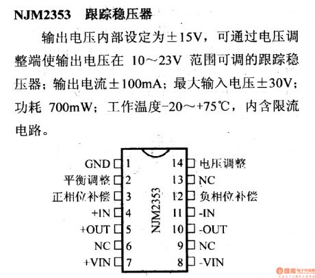
Interior output voltage of NJM 2353 tracking regulators is ±15V, and output voltage can be adjusted to 10~23V by the voltage adjusting terminal of the tracking regulator. The output current is ±100mA, maximum output voltage±30V, the power 700mW and the working temperature -20~+75℃. This regulator has an interior current-limiting circuit. (View)
View full Circuit Diagram | Comments | Reading(824)
Regulator DC-DC Circuit and Pin of Power Supply Monitor and its Main Features Swtiched regualtor
Published:2011/9/6 3:39:00 Author:Zoey | Keyword: Regulator, DC-DC Circuit, Pin of Power Supply Monitor, Swtiched regualtor
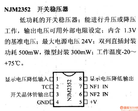
NJM 2353 switched regulator is a low-power-consumption regulator. It can increase voltage as well as decrease voltage, and the output voltage can be set by the external resistance. The regulator has an interior 1.3-V reference voltage. Maximum voltage of the power supply is 24V. This regulator is dual-inline packaged,with itspowerbeing 500mW, while power of microcapsule is 300mW. Its working temperature is -20~+75℃ (View)
View full Circuit Diagram | Comments | Reading(789)
Diagram of lithium battery protection circuit based on Xysemi XB4251A
Published:2011/9/7 8:09:00 Author:Vicky | Keyword: lithium battery, protection circuit
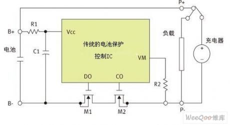
Schematic of lithium battery protection devices is shown in the above picture, which is realized mainly by battery protection control IC , exterior discharging switch M1 and charging switch M2. When P+/P- end is connected with charger, M1 and M2 are all under conducting state when the battery is charged normally; when the control IC detects any abnormality during charging, M2 is then cut off and charging process stops. When P+/P- end is connected with load, M1 and M2 are all under conducting state when the battery is discharging; when the control IC detects any abnormality, M1 is cut off and discharging process stops.
In addition, XB4301 cannot be reversely connected. XB4301 is mainly used in MP3 and Bluetooth at present, including partial mobiles, GPS application. (View)
View full Circuit Diagram | Comments | Reading(2264)
Regulator DC-DC Circuit and Pin of Power Supply Monitor and Voltage Detector
Published:2011/9/7 3:12:00 Author:Zoey | Keyword: Regulator, DC-DC Circuit, Pin, Voltage-detector
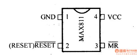
MAX811/MAX812 voltage-detector can detect 3.0-V, 3.3-V and 5.0-V voltage of power supply. Its current of power supply is 6A. Reset pulse width of SE is larger than 140ms. Output of MAX811 and MAX812 is RESET. The detectors have manually-reset function. If voltage of the power supply is less than 1V, MAX811 will keep RESET signal available. (View)
View full Circuit Diagram | Comments | Reading(843)
Regulator DC-DC Circuit and Pin of Power Supply Monitor and Step-up Regulator
Published:2011/9/7 3:33:00 Author:Zoey | Keyword: Regulator, DC-DC Circuit, Pin, Step-up Regulator
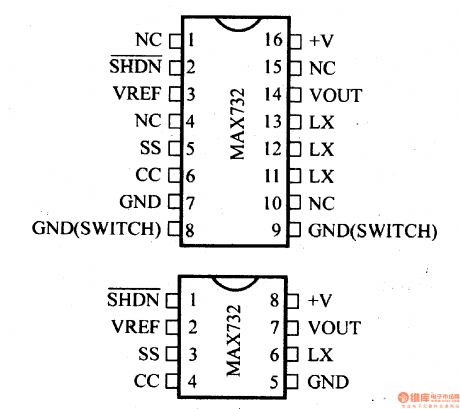
MAX732/733 refers to the DC-DC current PWM step-up regulator. As to MAX732, output voltage is +12V, maximum output current is 200mA, output voltage range is +4.0~+9.3V. And as to MAX733, the relevant values are +15V, 125mA and 4.0V~11.V respectively. Typical value of full load efficiency is 85%~92%, of empty load current is 1.7mA. Oscillation frequency is 170 kHz. The regulator has protection circuits for periodic current-proof, overcurrent-proof, undervoltage-proof and programmable soft-start. (View)
View full Circuit Diagram | Comments | Reading(1346)
Regulator DC-DC Circuit and Pin of Power Supply Monitor and Power Supply System
Published:2011/9/7 3:36:00 Author:Zoey | Keyword: Regulator, DC-DC Circuit, Pin, Power Supply System
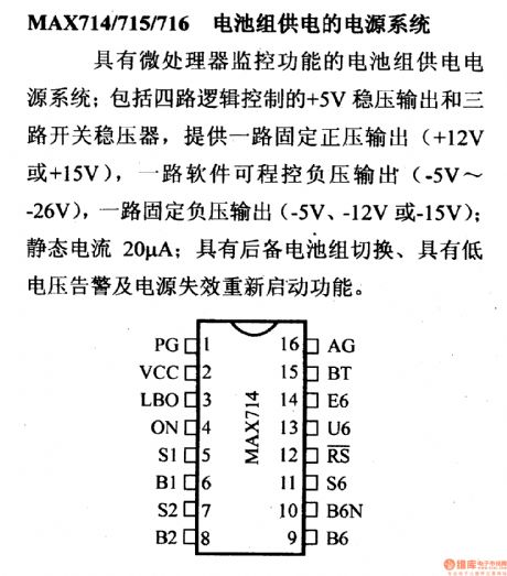
MAX714/715/716 refers to the power supply system powered by cell piles. It has a micro-processor for detection. This system consists of a four-loop logic-controlled +5-V regulator and a three-loop switched regulator, a fixed positive output single-loop(+12V or +15V), a software-controlled negative output single-loop and a fixed negative single-loop. Its static current is 20A. This system has a spare cell piles switch, a low voltage warner and it can restart if the cell lapses. (View)
View full Circuit Diagram | Comments | Reading(833)
Regulator DC-DC Circuit and Pin of Power Supply Monitor and Linear Debugger
Published:2011/9/7 22:53:00 Author:Zoey | Keyword: Regulator, DC-DC Circuit, Linear Debugger
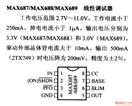
Working voltage range of MAX687/688/689 is 2.7V~11.0V. Its working current is below 250mA and power-off current is below 1µA. Output voltage of MAX676 and MAX688 is 3.3V, MAX689 is 3.0V. Current for driving external transistor should be larger than 10mA. Voltage will descend to 200mVwhen output currentreaches 500mA(2TX749). The accuracy is ±2%.
(View)
View full Circuit Diagram | Comments | Reading(882)
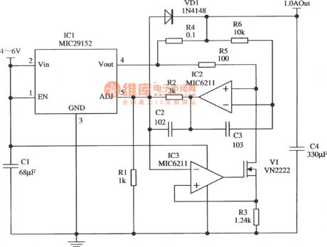
Constant Current Circuit Constituted By MIC29152 With The Output Current Of 1.0A
Published:2011/9/6 5:13:00 Author:Felicity | Keyword: Constant Current Circuit, Output Current, 1.0A
View full Circuit Diagram | Comments | Reading(1602)
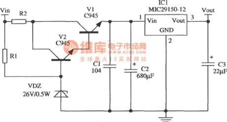
Circuit Of Wide-input Voltage Regulator Constituted By MIC29150-12
Published:2011/9/6 5:07:00 Author:Felicity | Keyword: Wide-input, Voltage Regulater
View full Circuit Diagram | Comments | Reading(1038)
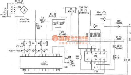
Portable Multi-charging Circuit Made Of LS325A
Published:2011/9/6 6:55:00 Author:Felicity | Keyword: Portable, Multi-charging
View full Circuit Diagram | Comments | Reading(1015)
Regulator DC-DC Circuit and Pin of Power Supply Monitor and its Main Features
Published:2011/9/6 22:02:00 Author:Zoey | Keyword: Regulator, DC-DC Circuit, Pin of Power Supply Monitor, Main Features
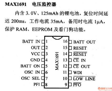
MAX1691 voltage-Monitor has an 3.0-V, 125-mAh lithium cell, thus the reset time will be postponed for 200ms. Its working current is 35mA, spare current is 1A. This monitor plays an importantrole in protecting RAM and EEPROM and it can work as a watchdog circuit. (View)
View full Circuit Diagram | Comments | Reading(786)
24V converting to 12V switching power supply circuit diagram
Published:2011/9/5 3:43:00 Author:Lucas | Keyword: switching power supply
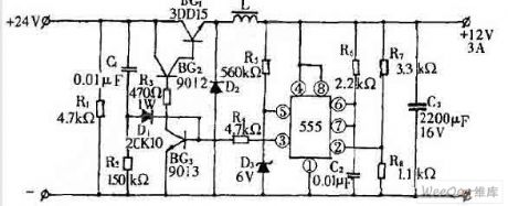
The 24V diesel vehicles is fitted with 12V electrical appliances (such as instruments, cassette players, fans, etc.), usually it uses 12V three-terminal regulator. However, due to voltage drop on the regulator is up to 12V, the power dissipation and temperature is too high to be damaged easily. We design a switching power supply transformer which can reduce 24V voltage to 12V, and the circuit is shown as the figure. This circuit uses 555 as a pulse oscillator. Pin ⑤ of 555 is connected to a regulator to obtain the +6 V reference voltage, and pin ② gets the sample voltage from the sampling circuit composed of R7, R8. When the pin voltage of pin ② is less than +3 V, pin ③ outputs high, so BG3, BG1, BG2 are saturated conduction and provide voltage for the load.
(View)
View full Circuit Diagram | Comments | Reading(2915)
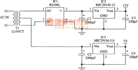
Low-cost Dual Output Regulator Circuit Composed Of MIC29152-12 And MIC29150-5.0
Published:2011/8/11 8:37:00 Author:Felicity | Keyword: Low-cost, Dual Output, Regulator
View full Circuit Diagram | Comments | Reading(1160)
| Pages:61/291 At 206162636465666768697071727374757677787980Under 20 |
Circuit Categories
power supply circuit
Amplifier Circuit
Basic Circuit
LED and Light Circuit
Sensor Circuit
Signal Processing
Electrical Equipment Circuit
Control Circuit
Remote Control Circuit
A/D-D/A Converter Circuit
Audio Circuit
Measuring and Test Circuit
Communication Circuit
Computer-Related Circuit
555 Circuit
Automotive Circuit
Repairing Circuit