
power supply circuit
Index 70
VARACTOR_FREQUENCY_QUADRUPLER
Published:2009/7/15 3:00:00 Author:Jessie
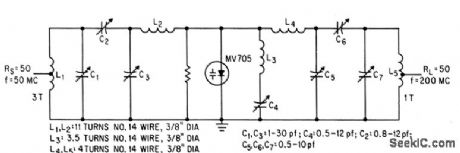
With 50-Mc input, output is 22 w at 200 Mc. Series-tuned idler circuit L3-C4 is omitted for frequency-doubling.-L. E. Clark, E. B. Mack, and R. C. Hejhall, Highlights of Small-Signal Circuit Design, Electronics, 36:49, p 46-50. (View)
View full Circuit Diagram | Comments | Reading(975)
HIGH_IMPEDANCE_DIFFERENTIAL_INPUTS
Published:2009/7/15 3:00:00 Author:Jessie
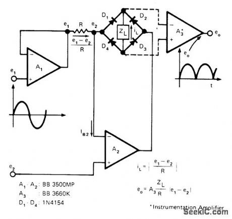
High impedance for both inputs of differential precision rectifier is provided by two opamps that produce current output for conversion to voltage by instrumentation amplifier A2. Diode bridge in feedback path of opamp A2 provides rectification with precise control for determining voltage drop across R. Design permits accurate measurement of differential AC inputs from millivolts to volts with AC voltmeter.-J. Graeme, Measure Differential AC Signals Easily with Precision Rectifiers, EDN Magazine, Jan. 20, t975, p 45-48. (View)
View full Circuit Diagram | Comments | Reading(1212)
SYNCHRONOUS_SAWTOOTH_FOR_PDM_TELE_METRY
Published:2009/7/14 4:24:00 Author:May
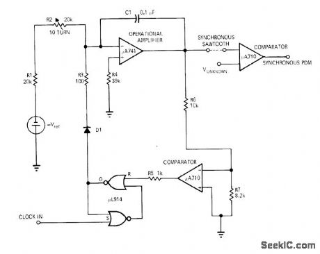
Circuit generates highly linear ramp that is reset to zero by each clock pulse. When ramp exceeds analog value of unknown input voltage, pulse is terminated. R1, R2, and C1 form integrating network around opamp. Varying R2 changes slope of ramp output. -J. Springer, Build a Sawtooth Generator with Three ICs, EDN Magazine, Nov. 15, 1970, p 49. (View)
View full Circuit Diagram | Comments | Reading(816)
BLOCKING_OSCILLATOR_SUPPLY
Published:2009/7/14 4:24:00 Author:May

Uses modified blocking oscillator to obtain square wave switching at 4,200 cps. Charges 300-mfd capacitor to 500 v in 5 to 10 sec from 9-v dry cell that can deliver up to 700 Bashes. To start oscillator, S1 momentarily connects R1 to negative side of battery.-H. A. Manoogian, Transistor Photoflash Power Converters, Electronics, 31:35, p 29-31. (View)
View full Circuit Diagram | Comments | Reading(1210)
TUNED_VOLTMETER
Published:2009/7/15 2:58:00 Author:Jessie
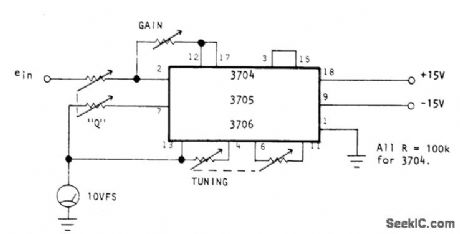
Optical Electronics active filter (3704 up to 5 kHz, 3705 up to 50 kHz, or 3706 up to 500 kHz) provides proper scale factor, impedance buffering, and isolation for measuring AC voltages at specific frequency. Circuit provides 100K input impedance and up to 10mA drive for 10-V meter. IC provides independent gain (scale factor or sensitivity), tuning, and Q (selectivity) adjustments.- Tuned Voltmeter, Optical Electronics, Tucson, AZ, Application Tip 10248. (View)
View full Circuit Diagram | Comments | Reading(1259)
PHOTOFLASH_SUPPLY
Published:2009/7/14 4:23:00 Author:May
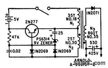
Flybcck or ringing choke oscillator is free-running when voltage on regulator capacitor C2 is less than zener voltage for reference diode D2, but converter action is halted when desired output voltage is reached. Circuit then periodically replaces charge lost by capacitor leakage.Energy conversion efficiency can therefore exceed 50% theoretical upper limit of most conventional photoflash circuits.-R. J. Sherin, Efficient Photoflash Power Converter, Electronics, 33:4, p 57. (View)
View full Circuit Diagram | Comments | Reading(1389)
V_F_CONVERTER
Published:2009/7/15 4:49:00 Author:Jessie

Can be used with any frequency counter. Only last three digits of display are read for voltage. VCO U22 runs at 1000 Hz when input is grounded and R3 is 56K. Counter is preset to 9000. For OV, count starts from 9000 and goes up to 10,000 on display, except that 1 at left overflows so reading is 0 V. If input is + 1 V, U22 goes upto 2000 Hz, appearing as 1000 on display. Voltage divider ahead of input is needed to divide full-scale voltages of 10, 100, and 1000 V down to basic 0-1 V range. Range switch is wired to place decimal in appropriate position. Use 2.7K for R2. DC voltages are in circles; upper value is for input probe of electronic voltmeter on +12 V, and lower value for input probe grounded. Terminal A goes to over range and reverse polarity indicators using 5558 dual opamp U23 and Archer (Radio Shack) 276-041 or equivalent LEDs. R4 and R5 depend on input-signal excursion range and exact value of sup-ply; start with 2700 ohms for R4 and 18K for R5.-J. Hall and C. Watts, Learning to Work with Integrated Circuits, QST, June 1976, p 20-24; revised circuit in June 1977, p 20-21. (View)
View full Circuit Diagram | Comments | Reading(2195)
BALANCED_FET_DC_VOLTMETER
Published:2009/7/15 4:38:00 Author:Jessie
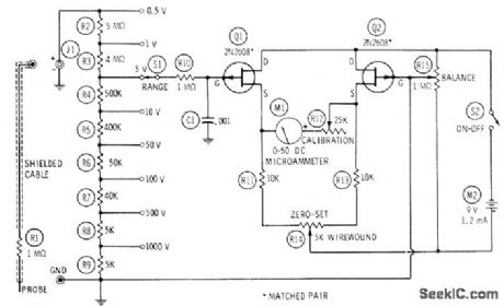
Factory-matched FETs are connected in resistance bridge that is balanced by 814 to make meter read zero for 0-V input voltage. Voltage divider provides eight ranges, using 1% resistors for accuracy. Some must be made up by using two or more resistors in series. Balanced circuit has very low temperature drift, reducing number of times rebalancing is needed.-R. P. Turner, FET Circuits, Howard VV. Sams, Indianapolis, IN, 1977, 2nd Ed., p 119-122. (View)
View full Circuit Diagram | Comments | Reading(1960)
PROBABILITY_MULTIPLIER
Published:2009/7/15 4:34:00 Author:Jessie
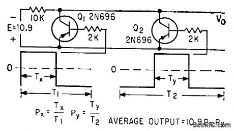
Based on converting two analog factors to duty cycles of pulse trains of uncorrelated repetition rate. Pulse-train control of and gate is such that there is no output unless both trains are simultaneously positive, and then average value of gate output is proportional to product. -T. R. Hoffman, Analog Multiplication Using Time as One Variable, Electronics, 33:33, p 136-138. (View)
View full Circuit Diagram | Comments | Reading(838)
ANALOG_VOLTAGE_MULTIPLIER
Published:2009/7/15 4:05:00 Author:Jessie
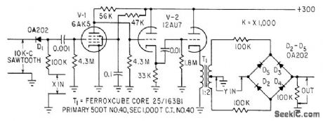
Pulse-width modulator and push-pull rectangular pulse generator driving diode-bridge switch give product of two input voltages X and Y, which must be in range of -10 V to +10 V. Input circuit of pulse-width modulator D1-V1 is supplied by 10-kc negative-slope sawtooth and input variable X.-J. Ash and Y. J. Fokkinga, Inexpensive Multiplier for Analog Computers, Electronics, 35:18, p 37. (View)
View full Circuit Diagram | Comments | Reading(1529)
DVM_IC_DRIVES_METER
Published:2009/7/15 3:50:00 Author:Jessie

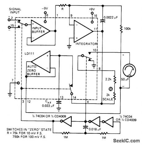
Uses Siliconix LD111 IC analog processor section of digital voltmeterIC pair to combine desirable features of digital voltmeter with signal-averaging advantages of ordinary meter. Input range covered is 10 mV to 3 V, with resistive divider being required for larger input voltage. Differential inputs each have 1-gigohm input impedance. Circuit requires only two 9-V batteries. Article describes operation in detail.-B. Harvey, Digital Voltmeter IC Drives Analog Meter, EDN Magazine, June 20, 1977, p 113. (View)
View full Circuit Diagram | Comments | Reading(1001)
COMPARATOR_SEPARATES_STNC_PULSES
Published:2009/7/15 3:49:00 Author:Jessie
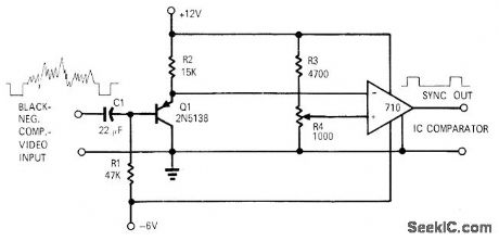
By setting DC reference input of 710 comparator at 0.15 CDC.only horizontal sync pulses are extracted from composite black-negative video signal to appear at comparator output Setting reference level at 0.35 VDC gives only blanking pulses at output.-R,G, Groom IC Comparator Separates Sync Pulses EDN Magazine, Sept 15.1970.p 53-54. (View)
View full Circuit Diagram | Comments | Reading(854)
PHASE_SENSITIVE_DEMODULATOR
Published:2009/7/15 3:48:00 Author:Jessie
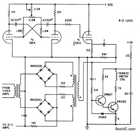
Used in iceberg-detecting microwave radiometer. Faraday rotational ferrite switch alternately feeds calibrating noise source and ocean or iceberg signal through video amplifier to double-bridge demodulator. Output is d-c voltage proportional to change in antenna temperature, positive for warm signals from iceberg and negative for apparently colder sea water. Mvbr (125 cps) supplies reference voltage and ferrite drive signal.-T. V. Seling and D. K. Nance, Sensitive Microwave Radiometer Detects Small Icebergs, Electronics, 34:19, p 72-75. (View)
View full Circuit Diagram | Comments | Reading(1044)
PRECISION_CURRENT_SOURCE
Published:2009/7/14 3:32:00 Author:May
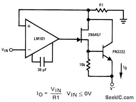
2N5457 JFET and PN2222 bipolar transistor serve as isolators between output and current-sensing resistor R1. LM101 opamp provides high loop gain to assure that circuit acts as current source.- FET Databook, National Semiconductor、Santa Clara、GA、1977、p6-26-6-36. (View)
View full Circuit Diagram | Comments | Reading(0)
ADJUSTABLE_REFERENCE
Published:2009/7/15 20:57:00 Author:Jessie
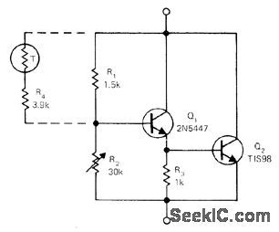
Two-transistor equivalent of zener is combined with Gulton 35TF1 thermistor to give voltage stability within 0.5% over 0-50℃ range, with output voltage adjustable from 3.5 to 15.5 V with R2. Dynamic impedance is only 1 ohm. Developed for regulator service in battery-powered MOS instruments.-R. Tenny, Compensated Adjustable Zener, EDN Magazine, May 5, 1973, p 72. (View)
View full Circuit Diagram | Comments | Reading(907)
_69_V_TO+69_V_VARIABLE
Published:2009/7/15 20:56:00 Author:Jessie
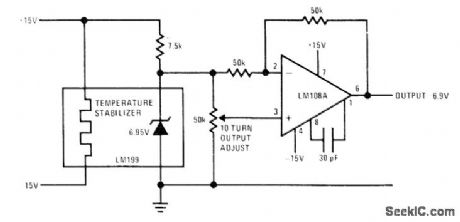
National LM199 temperature-stabilized 6.95-V reference is converted to continuously variable bipolar output by LM108A opamp,Use precision wirewound 10-turn pot. Opamp operates as inverter for negative outputs but is noninverting for positive outputs.- Linear Applications, Vol. 2, National Semiconductor, Santa Clara, CA, 1976, AN-161,p6. (View)
View full Circuit Diagram | Comments | Reading(918)
15_12_V_FOUROUTPUT
Published:2009/7/15 20:46:00 Author:Jessie
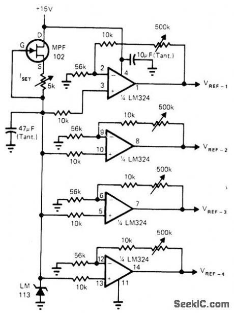
Single LM113 1.22-V stable reference is driven by 1-mA FET constant-current source to provide highly stable low-voltage standard driving four adjustable-gain opamps. Gain of each is set to give desired output reference voltage in range from 1.5 to 12 V. Use cermet trimmers and metal-oxide fixed resistors in opamp feedback circuits to achieve stabilities of several millivolts over 0 to 70℃ range.-H. Olson, Two IC's and FET Provide Quad Stable Reference, EDN Magazine, Jan. 20, 1974, p 82.
(View)
View full Circuit Diagram | Comments | Reading(917)
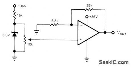
0005_REGULATION
Published:2009/7/15 20:44:00 Author:Jessie

Simple opamp circuit changes less than 1 mV at output for input range of 10-30 V. Circuit is easily modified to give other output voltages, either positive or negative.-M. Walne, High Performance Reference, Wireless World, May 1974, p 123. (View)
View full Circuit Diagram | Comments | Reading(823)
VARIABLE_REFERENCE
Published:2009/7/15 20:43:00 Author:Jessie
With 759 power opamp used as variable-output voltage regulator, output voltage can be varied over full range from zener maximum down to zero by varying voltage from zener. With 791 opamp, voltage can be adjusted down to 2 V. Since output voltage can be less than zener rating, simple boot- 68V strapping cannot be used. Alternate biasing techniques are then required to improve line regulation. Arrangement is capable of supplying several hundred milliamperes while using only low-drift (5 PPM/℃) zener.-R. J. Apfel, Power Op Amps-Their Innovative Circuits and Packaging Provide Designers with More 0ptions, EDN Magazine, Sept. 5, 1977, p 141-144. (View)
View full Circuit Diagram | Comments | Reading(1027)
PHASE_DISCRIMINATOR
Published:2009/7/15 20:35:00 Author:Jessie
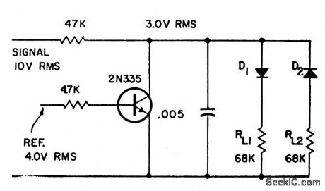
Will deliver half-wave pulses to one of two loads, as determined by 0 or 180° difference between input signal and reference source. Useful where different devices, such as heating and cooling equipment, are to be actuated by change of signal phase.-A Phase Discriminator, Electronic Circuit Design Handbook, Mactier Pub. Corp. N.Y.1965, p 88. (View)
View full Circuit Diagram | Comments | Reading(1574)
| Pages:70/291 At 206162636465666768697071727374757677787980Under 20 |
Circuit Categories
power supply circuit
Amplifier Circuit
Basic Circuit
LED and Light Circuit
Sensor Circuit
Signal Processing
Electrical Equipment Circuit
Control Circuit
Remote Control Circuit
A/D-D/A Converter Circuit
Audio Circuit
Measuring and Test Circuit
Communication Circuit
Computer-Related Circuit
555 Circuit
Automotive Circuit
Repairing Circuit