
power supply circuit
Index 64
The regulator: DC-DC circuit and power supply monitor pin and its main features LM196/396
Published:2011/8/29 2:37:00 Author:Seven | Keyword: regulator, power supply, monitor pin
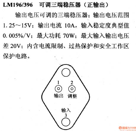
LM196/396--the adjustable 3-terminal stabilizer (positive output)This is a 3-terminal stabilizer with a fixed output voltage; the output voltage is 1.25~15V; the output current is 10A, the input stability typical value is 0.005%/V; the max power consumption is 70w; the max input-output voltage difference is 20V; it contains the current limitation, overheat protection and secure working area protection circuit.
(View)
View full Circuit Diagram | Comments | Reading(834)
The regulator: DC-DC circuit and power supply monitor pin and its main features LM185-1.2/285-1.2/385-1.2
Published:2011/8/29 2:48:00 Author:Seven | Keyword: regulator, power supply, monitor pin
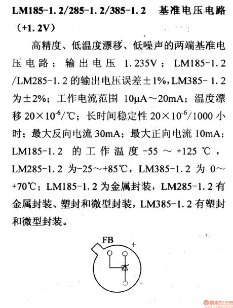
LM185-1.2/285-1.2/385-1.2--the reference voltage circuit (+1.2V)This is a 2-terminal reference voltage circuit of high-precision, low-temperature drift and low-noise; the output voltage is 1.235V; the output voltage fault of LM185-1.2/LM285-1.2 is ±1% and that of LM385-1.2 is ±2%; the working current range is 10μA~20mA; the temperature drift is 20*10-6/℃; the long-term stability is 20*10-6/1000h, the max inverting current is 30mA; the max non-inverting current is 10mA; the working temperature of LM185-1.2 is -55~+125℃.
(View)
View full Circuit Diagram | Comments | Reading(607)
The regulator: DC-DC circuit, power supply monitor pin and its main features LM1851
Published:2011/8/23 22:23:00 Author:Seven | Keyword: DC-DC circuit, power supply, monitor pin
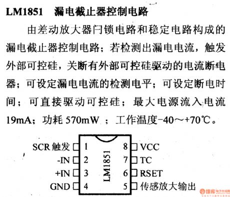
LM1851--the electricity leakage halter control circuit This is an electricity leakage halter control circuit composed of the difference amplifier lock circuit and stable circuit; if the electricity leakage is tested out, the external SCR is triggered, all the electricity halters with external SCR is cut off; the testing LEV of the leaking current can be set; the current breakdown time can be set; it can directly drive the SCR; the maximum current source input current is 19mA; the power consumption is 570mA; working temperature is -40~+70⁰C.
(View)
View full Circuit Diagram | Comments | Reading(765)
The regulator: DC-DC circuit, power supply monitor pin and its main features LM120
Published:2011/8/24 22:07:00 Author:Seven | Keyword: DC-DC circuit, power supply, monitor pin
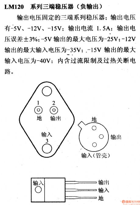
The 3-terminal stabilizer (negative output) of LM120 series This is a 3-terminal stabilizer with fixed output voltage; the output voltage can be -5V, -12V and -15V; the output current is 1.5A; the output voltage fault is ±3%; when the output is -5V, the max output voltage is -25V; when the output is -12V, the max output voltage is -35V; when the output is -15V, the max output voltage is -40V; it contains the over-current limitation and over-heat cutoff circuit.
(View)
View full Circuit Diagram | Comments | Reading(687)
The regulator: DC-DC circuit, power supply monitor pin and its main features LM117/217/317
Published:2011/8/24 22:15:00 Author:Seven | Keyword: DC-DC circuit, power supply, monitor pin
LM117/217/317--the adjustable 3-terminal stabilizer (positive output) This is a 3-terminal stabilizer with adjustable output voltage; its output voltage range is 1.2~37v; the max output current is 1.5A; the typical value of input stability is 0.01%/V; the max input-output voltage gap is 40V; it contains the current limitation, over-heat protection and secure working area protection circuit; the approximate types are μA117, μA217, μA317, SG117, SG217, SG317, CW117, CW217, CW317.
(View)
View full Circuit Diagram | Comments | Reading(1169)
The regulator: DC-DC circuit, power supply monitor pin and its main features LM150/250/350
Published:2011/8/23 22:23:00 Author:Seven | Keyword: DC-DC circuit, power supply, monitor pin
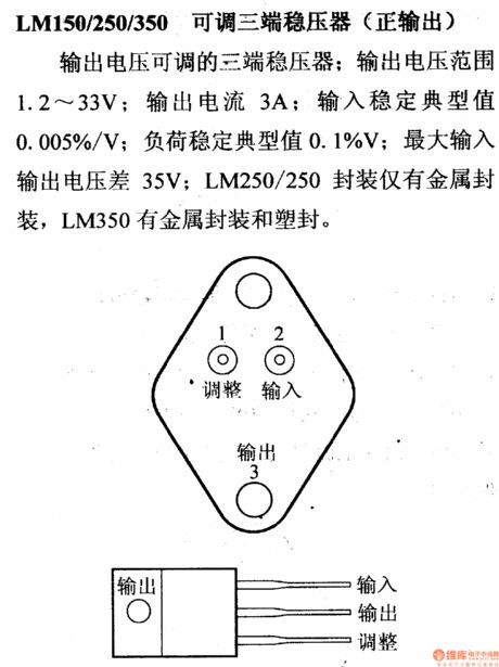
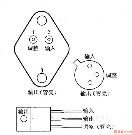
LM150/250/350--the changeable 3-terminal regulator (forward output) This is a 3-terminal regulator whose output voltage is adjustable; its output voltage range is 1.2~33V; its output current is 3A; its input stable typical value is 0.005%/V; its load stable typical value is 0.1%V; the maximum input-output voltage difference is 35V; LM250/250 is only packaged in metal package, LM350 can be packed in either metal or plastic package.
(View)
View full Circuit Diagram | Comments | Reading(962)
The regulator: DC-DC circuit, power supply monitor pin and its main features LM123/223/323
Published:2011/8/24 21:59:00 Author:Seven | Keyword: DC-DC circuit, power supply, monitor pin
LM123/223/323--the 5V stabilizer This is a stabilizer with fixed output voltage; the output voltage is 5V; the output current is 3A; the typical value of its output impedance is 0.01Ω; the max input-output voltage difference 20V; the power consumption is 30W; it contains the current limitation, power limitation and over-heat cutoff circuit.
(View)
View full Circuit Diagram | Comments | Reading(659)
The regulator: DC-DC circuit, power supply monitor pin and its main features M51920P
Published:2011/8/28 3:00:00 Author:Seven | Keyword: DC-DC circuit, power supply, monitor pin
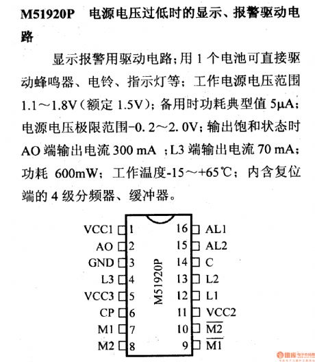
M51920P--the display and alarm drive circuit when the power supply voltage is too lowThis is a drive circuit of displaying alarm; the buzzer, ring and indicator can be driven by 1 cell; the voltage range of the working power supply is 1.1~1.8V(the regulated voltage is 1.5V); the additional power consumption typical value is 5μA; the power supply limit range is -0.2~2.0V; when the output is saturated, the output current of AO terminal is 300mA; the output current of L3 is 70mA; the power consumption is 600mW; the working temperature is -15~+65℃; it contains the 4-stage frequency distributor and buffer of the reset terminal.
(View)
View full Circuit Diagram | Comments | Reading(658)
The regulator: DC-DC circuit, power supply monitor pin and its main features M5231
Published:2011/8/28 2:49:00 Author:Seven | Keyword: DC-DC circuit, power supply, monitor pin
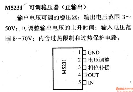
M5231--the adjustable stabilizer (positive output)This is a stabilizer whose output voltage is adjustable; the output voltage range is 3~50V; the step-up time of the output voltage can be adjusted; the input voltage range is 8~70V; it contains the over-heat limitation and over-heat protection circuit.
(View)
View full Circuit Diagram | Comments | Reading(1603)
The regulator: DC-DC circuit, power supply monitor pin and its main features M5231TL
Published:2011/8/28 2:46:00 Author:Seven | Keyword: DC-DC circuit, power supply, monitor pin
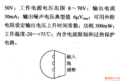
M5231TL--the adjustable stabilizer (positive output)This is a stabilizer whose output voltage is adjustable; the output voltage range is 3~50V; the voltage range of the working power supply 8~70V; the output current 20mA; the typical value of the output noise voltage is 6μVrms; the output voltage step-up time of the available external resistor is set to be a constant; the power consumption 300mW; the working temperature -20~+75℃; it contains the current limitation and over-heat protection circuit.
(View)
View full Circuit Diagram | Comments | Reading(636)
The regulator: DC-DC circuit, power supply monitor pin and its main features M5236
Published:2011/8/28 2:38:00 Author:Seven | Keyword: DC-DC circuit, power supply, monitor pin
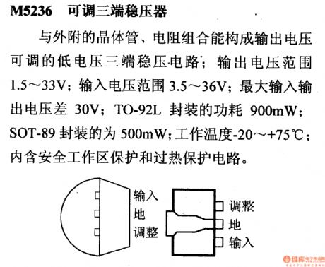
M5236--the adjustable 3-terminal stabilizerIt composes the 3-terminal regulated circuit whose output voltage adjustable with the external transistor and resistor; the output voltage range is 1.5~33V; the input voltage range is 3.5~36V; the max input-output voltage difference is 30V; the power consumption of the TO-92L is 900mW, and that of SOT-89 package is 500mW; the working temperature is -20~+75℃; in contains the secure working area protection and over-heat protection circuit.
(View)
View full Circuit Diagram | Comments | Reading(801)
The regulator: DC-DC circuit, power supply monitor pin and its main features LM113/313
Published:2011/8/24 22:24:00 Author:Seven | Keyword: DC-DC circuit, power supply, monitor pin
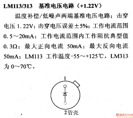
LM113/313--the Vref circuit (+1.22V) This is a 2-terminal Vref circuit of temperature compensation/low-noise; the breakdown voltage is 1.22V; the breakdown voltage fault is ±5%; the working current range is 0.5~20mA; the working impedance typical value in the working current is 0.3Ω; the max forward current is 50mA; the max backward current is 50mA; the working temperature of LM113 is -55~+125℃ and that of LM313 is 0~70℃.
(View)
View full Circuit Diagram | Comments | Reading(709)
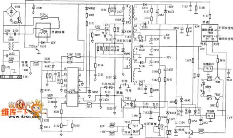
Color monitor switching power supply (TEAl504) circuit diagram
Published:2011/8/24 22:02:00 Author:Ecco | Keyword: Color monitor , switching power supply
View full Circuit Diagram | Comments | Reading(1142)
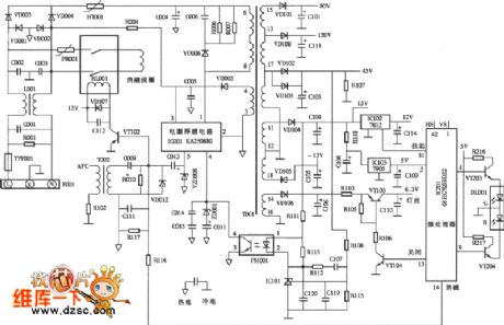
Color monitor switching power supply (KA2S0880) circuit diagram
Published:2011/8/24 22:02:00 Author:Ecco | Keyword: Color monitor , switching power supply
View full Circuit Diagram | Comments | Reading(3431)
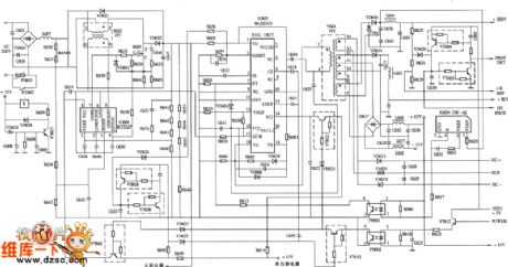
Color monitor switching power supply (MC33262p) circuit diagram
Published:2011/8/24 22:10:00 Author:Ecco | Keyword: Color monitor , switching power supply
View full Circuit Diagram | Comments | Reading(2427)
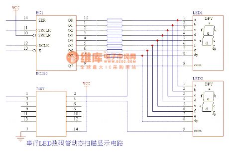
Serail LED Nixie Tube Dynamic Scanning Display Circuit
Published:2011/8/13 23:59:00 Author:Joyce | Keyword: Serail , LED , Nixie Tube, Dynamic, Scanning, Display
View full Circuit Diagram | Comments | Reading(813)
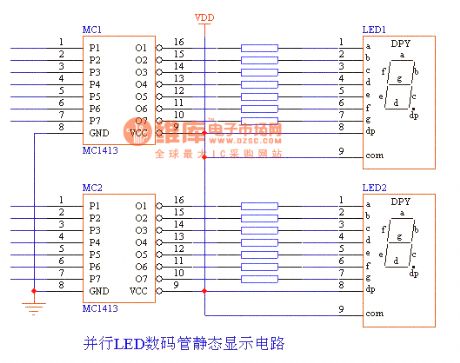
Parallel LED Nixie Tube Static Display Circuit
Published:2011/8/14 0:54:00 Author:Joyce | Keyword: Parallel , LED , Nixie Tube , Static , Display
View full Circuit Diagram | Comments | Reading(765)
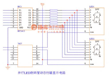
Parallel LED Nixie Tube Dynamic Scanning Display Circuit
Published:2011/8/14 0:55:00 Author:Joyce | Keyword: Parallel, LED , Nixie Tube , Dynamic , Scanning , Display
View full Circuit Diagram | Comments | Reading(829)
Voltage Regulator Circuit Composed Of Zener Diodes
Published:2011/8/23 23:40:00 Author:Robert | Keyword: Voltage, Regulator, Zener, Diode
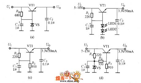
The picture shows the voltage regulator circuit composed of zener diodes. And, the picture (a) shows the circuit with output of 6V/50mA. Now it introduces the determining method of the each components in the circuit. The input voltage U is 10V~16V, and at this time the output voltage Uo=Uz-UBE. The transistor VT1's UBE is fixed which is about 0.65V. So the VS's stable voltage is Uz=6V+0.65V=6.65V. It could use the RD6.8EB1 zener diode.The picture shows the voltage regulator circuit composed of zener diodes.(a)The circuit with output of 6V/50mA. (b)The circuit which using LEDs to replace the zener diodes. (c)The circuit which using the resistance for voltage dividing. (d) The voltage regulator circuit which has the best performance. (View)
View full Circuit Diagram | Comments | Reading(2511)
Voltage Regulator Circuit With Auxiliary Power
Published:2011/8/23 23:40:00 Author:Robert | Keyword: Voltage, Regulator, Auxiliary, Power
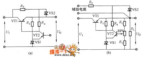
The circuit shown in picture (b) can not stabilize well for the transient voltage. Because this transient voltage could be through the resistance R4 and add to the output port through the amplification of the adjustment tube. Also in the circuit shown in picture (b), the amplifier's power, which is the input voltage U1, is also not stabilized. So it could add the R4 directly to the power input port and make the amplifier's power stable, which is shown in picture (a). But in order to make the zener diode VS2 work normally in the circuit, it must make the adjustment tube VT1's tube voltage drop UCE larger than the VS2's working voltage. This would increase the VT1's power consumption. (View)
View full Circuit Diagram | Comments | Reading(839)
| Pages:64/291 At 206162636465666768697071727374757677787980Under 20 |
Circuit Categories
power supply circuit
Amplifier Circuit
Basic Circuit
LED and Light Circuit
Sensor Circuit
Signal Processing
Electrical Equipment Circuit
Control Circuit
Remote Control Circuit
A/D-D/A Converter Circuit
Audio Circuit
Measuring and Test Circuit
Communication Circuit
Computer-Related Circuit
555 Circuit
Automotive Circuit
Repairing Circuit